

Page 1
English: Page 1 Español: Página 37
Deutsche: Seite 13 Português: Página 49
Français: Page 25
OPERATING
WIRELESS MICROPHONE SYSTEM
INSTRUCTIONS
S4.04 / S4.10 series
CONTENTS
1. SAFETY PRECAUTIONS
2. GENERAL DESCRIPTION
3. FEATURES
4. HANDLING PRECAUTIONS
5. NOMENCLATURE AND FUNCTIONS
6. CHANNEL NUMBER SETTING by MANUAL
7. CHANNEL NUMBER SETTING by
INFRARED SYNCHRONIZATION
8. CHANNEL SCAN
9. BATTERY ALARM
10. OPERATIONAL HINTS
11. TROUBLESHOOTING
12. SPECIFICATIONS
Thank you for purchasing TOA's TRANTEC S4 series Wireless Microphone system.
Please carefully follow the instructions in this manual to ensure long, trouble-free use of your equipment.
Page 2

2
1. SAFETY
• Be sure to read the instructions in this section carefully before use.
• Make sure to observe the instructions in this manual as the conventions of safety symbols and messages
regarded as very important precautions are included.
• We also recommend you keep this instruction manual handy for future reference.
Safety Symbol and Message
Safety symbols and messages described below are used in this manual to prevent bodily injury and property
damage which could result from mishandling. Before operating your product, read this manual first and
understand the safety symbols and messages so you are thoroughly aware of the potential safety hazards.
PRECAUTIONS
Conventions
WARNING
Indicates a potentially hazardous situation which, if mishandled, could
result in death or serious personal injury.
When Installing the Receiver
• Do not expose the unit to rain or an environment where it may be splashed by water or other liquids, as
doing so may result in fire or electric shock.
• Use the unit only with the voltage specified on the unit. Using a voltage higher than that which is specified
may result in fire or electric shock.
• Do not cut, kink, otherwise damage nor modify the power supply cord. In addition, avoid using the power
cord in close proximity to heaters, and never place heavy objects -- including the unit itself -- on the power
cord, as doing so may result in fire or electric shock.
• Avoid installing or mounting the unit in unstable locations, such as on a rickety table or a slanted surface.
Doing so may result in the unit falling down and causing personal injury and/or property damage.
• To prevent lightning strikes, install the unit at least five meters away from a lightning rod, and yet within the
protective range (angle of 45°) of the lightning conductor. Lightning strikes may cause a fire, electric shock
or personal injury.
• Since the unit is designed for in-door use, do not install it outdoors. If installed outdoors, the aging of parts
causes the unit to fall off, resulting in personal injury. Also, when it gets wet with rain, there is a danger of
electric shock.
When the Receiver is in Use
• Should the following irregularity be found during use, immediately switch off the power, disconnect the power
supply plug from the AC outlet and contact your nearest TOA dealer. Make no further attempt to operate the
unit in this condition as this may cause fire or electric shock.
· If you detect smoke or a strange smell coming from the unit.
· If water or any metallic object gets into the unit
· If the unit falls, or the unit case breaks
· If the power supply cord is damaged (exposure of the core, disconnection, etc.)
· If it is malfunctioning (no tone sounds.)
• Do not place cups, bowls, or other containers of liquid or metallic objects on top of the unit. If they
accidentally spill into the unit, this may cause a fire or electric shock.
• Do not touch the unit's antennas during thunder and lightning, as this may result in electric shock.
When the Microphone or the Transmitter is in Use
• To prevent the electromagnetic wave from badly inf lue nci ng m edi cal equ ipm ent , ma ke s ure to switch
off the unit's power when placing it in close proximity to the medical equipment.
Page 3

3
CAUTION
Indicates a potentially hazardous situation which, if mishandled,
could result in moderate or minor personal injury, and/or property
damage.
When Installing the Receiver
• Never plug in nor remove the power supply plug with wet hands, as doing so may cause electric shock.
• When unplugging the power supply cord, be sure to grasp the power supply plug; never pull on the cord
itself. Operating the unit with a damaged power supply cord may cause a fire or electric shock.
• When moving the unit, be sure to remove its power supply cord from the wall outlet. Moving the unit with the
power cord connected to the outlet may cause damage to the power cord, resulting in fire or electric shock.
When removing the power cord, be sure to hold its plug to pull.
• The socket outlet shall be installed near the equipment and shall be easily accessible.
• Avoid installing the unit in humid or dusty locations, in locations exposed to the direct sunlight, near the
heaters, or in locations generating sooty smoke or steam as doing otherwise may result in fire or electric
shock.
When the Receiver is in Use
• Do not place heavy objects on the unit as this may cause it to fall or break which may result in personal injury
and/or property damage. In addition, the object itself may fall off and cause injury and/or damage.
• Make sure that the volume control is set to minimum position before power is switched on. Loud noise
produced at high volume when power is switched on can impair hearing.
• Never open the unit case as there are high temperature parts inside the unit, which may cause a burn if
touched. Refer all servicing to your nearest TOA dealer.
• Use the dedicated AC adapter for the unit. Note that the use of other adapter may cause a fire.
• If dust accumulates on the power supply plug or in the wall AC outlet, a fire may result. Clean it periodically.
In addition, insert the plug in the wall outlet securely.
• Switch off the power, and unplug the power supply plug from the AC outlet for safety purposes when cleaning
or leaving the unit unused for 10 days or more. A fire or electric shock may result.
• Any modifications made to this device that are not approved by TOA Corporation may void the authority
granted to the user to operate this equipment.
• Operation of this device is subject to the following two conditions: (1) this device may not cause interference,
and (2) this device must accept any interference, including interference that may cause undesired operation
of the device.
When the Microphone or the Transmitter is in Use
• When the unit is not in use for 10 days or more, be sure to take the battery out of the unit because battery
leakage may cause personal injury or contamination of environment.
• Make sure to observe the following handling precautions so that a fire or personal injury does not result from
leakage or explosion of the battery.
· Do not short, disassemble heat nor put the battery into a fire.
· Do not solder a battery directly.
· Be sure to use the specified type of battery.
· Note corr ect pola rity (p ositive and negative orientation) when inserting a battery in the unit.
· Avoid locations exposed to the direct sunlight, high temperature and high humidity when storing batteries.
• When the battery becomes inflated or leaks, discontinue use and replace with new one immediately.
CAUTION TO USER: Changes or modifications not expressl y approv ed by the party r esponsible for
compliance could void the user's authority to operate the equipment.
IMPORTANT NOTE: To comply with the FCC RF exposure compliance requirements, no change to the
antenna or the device is permitted. Any change to the ant enna or the device could result in the device
exceeding the RF exposure requirements and void user’s authority to operate the device.
Page 4

4
IMPORTANT NOTE:
This device complies with Industry Canada’s licence-exempt RSSs. Operation is subject to the following two
conditions:
(1) This device may not cause interference; and (2) this device must accept any interference, including
interference that may cause undesired operation of the device.
Le pr ésen t a ppa r e il e st c o nform e aux CNR d'Industrie Canada applicables aux appareils radio exempts de
licence. L'exploitation est autorisée aux deux conditions suivantes : (1) l'appareil ne doit pas produire de
brouillage, et (2) l'utilisateur de l'appareil doit accepter tout brouillage radioélectrique subi, m ême si l e
br o u illage e s t s uscept i b l e d'en compromettre le fonctionnement.
2. GENERAL
The TOA’s TRANTEC S4 series W ir e le ss M ic r op ho n e s y st e m is designed for use on the UHF
f r eq ue n c y band, and suitable for vocal or speech reinforcement applications. It features a compander
circuit which minimizes the influence of ambient noise.
S4.04 : 4 User selectable channels that can be operated simultaneously.
S4.10 : Up to 16 User selectable channels that can be operated simultaneously. (depending on region)
S4 series HDX Wireless handheld Microphone is a vocal microphone, employing a fine, powerful dynamic
microphone unit.
S4 series BTX Wireless belt-pack transmitter can use TRANTEC series lavalier microphones and headset
microphones.
S4 series RX Wireless receiver is a diversity receiver to minimize drop-outs.
DESCRIPTION
3.
FEATURES
• An optimized PLL-synthesizer minimizes the oscillation frequency drift resulting from the ambient temperature
or voltage fluctuation.
• Power/Battery lamps indicate battery consumption to prevent the unit from malfunctioning when the battery
level remarkably decreases.
• Up to 10 hours of continuous use with single AA alkaline battery.
• S4 series HDX employs a built-in antenna.
• The state of battery consumption can be displayed on S 4 se ri e s RX receiver's indicator.
• Quick channel scanning and auto channel set-up.
• Infra-red auto channel set-up.
• Compact size and high reliability.
4. HANDLING
• Do no t expose the unit to rain or an envi ro nment where it ma y be splashed by water or other liquids,
as do in g so may result in unit fai lure.
• Neve r open nor remove the unit case to modify the unit. Refer all servicing to your nearest TOA
dea le r.
• Take care not to drop t he unit ont o the floor nor bump it against a hard obj ect as the unit could fail.
• Do not place the unit in locations of high temperature (e.g. in an ill-v en tilated car in summer) or
high humidity as the unit could fail.
• Do no t use the unit in locations where it is exposed to seawater.
• Avoid using a mobile telephone near the wireless microphone in use. Noise could be picked up.
• When installing, keep the unit as far away as possible from fluorescent lamps, digital equipm en t,
per so nal computers, and other equipm ent that gene rate high frequency noise.
• To clean, use a dry cloth. When the unit gets very dirty, wipe lightly with a cloth dampened in a
dilute neutral cleanser, t hen wi pe with a dry cloth. Never use benzene, thinner, or chemicallytreat ed cleani ng towel.
• When using two or m ore wirele ss microphones, keep th em at l ea st 50 cm away fr om each other to
avoid m alfunctions or noise.
• Keep the wireless microph one at least 3 m away from th e receiving antenna . Using the microp hone
in close proximity to the antenna could result in malfunctions or noise.
PRECAUTIONS
Page 5
5
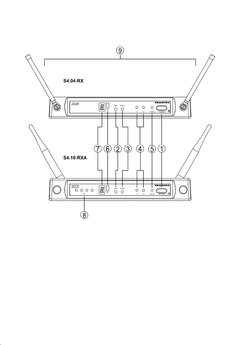
5. NOMENCLATURE AND
Receiver : S4.04-RX & S4.10-RXA
[Front]
S4.04-RX
S4.10-RXA
FUNCTIONS
1. Power switch
Press this switch to turn the power on, and press it
again to turn the power off.
2. Channel setting key [SET]
Used to select the receiving channel (frequency).
(The receiver frequency must be identical to that of
the microphone.)
3. Infrared (IR) sync key [SYNC]
Press this switch to transfer the frequency to
the transmitter.
4. Reception lamps [A, B]
Either lamp A (left) or B (right) lights yellow
when the receiver matches a radio signal from the
transmitter.
5. AF peak lamp [PEAK]
Lights red when the receiver output level reaches
the point about 3 dB below the clipping level.
6. Infrared (IR) port [IR]
Transmit the infrared signal, when pressing
SYNC key,
7. Numerical LED display
Indicates the current channel number in normal
state.
In setting mode, the indicated channel number
flashes until registered.
8. RF signal level meter (S4.10-RXA only)
Indicates the RF signal level.
9. Antennas (S4.04-RX only)
Raise b oth ant en nas at 45° outwards fr om
a vertical line.
When carrying the unit, be sure to fold down
both antennas to prevent them from break.
Page 6

6
[Rear]
S4.04-RX
S4.10-RXA
10. DC input jack
Conne ct the power cable of the supplied
AC adapter to this jack.
11. Cable hanger
Hook the power cable onto this part.
Tip S4.10-RXA receiver gain is continuously adjustable. Should the receiver signal be too high, it will distort
your mixer / amplifier. If the signal is too low, the result will be an increase in general background noise.
Monitor the AF peak LED on the receiver, and adjust the volume control to achieve the best signal
quality.
12. AF output
Balanced XLR jack, male type (Pin #2: Hot).
S4.04-RX : -20 dBu (maximum)
S4.10-RXA : 16 dBu (maximum)
13. AF output
Unbalanced phone jack
S4.04-RX and S4.10-RXA : 10 dBu (maximum)
14. Volume control (S4.10-RXA only)
Adjust the output level.
15. Antenna input A, B (S4.10-RXA only)
BNC connectors for antennas
Phantom powering for the external
antenna (optional)
For the wireless system covering a relatively
narrow area, use the supplied two rod antennas,
which should be set up at 45° outwar ds fr om
a vertical line.
Page 7

7
Handheld microphone : S4.04-HDX & S4.10-HDX
Page 8

8
Belt-pack transmitter : S4.04-BTX & S4.10-BTX
Page 9

9
1. Power switch
Slide this switch towards “ON” to turn the
power on, and slide it again towards “OFF” to
turn the power off.
2. Power / Battery lamp
A green LED lights as long as the battery
capacity is sufficient. When the battery
capacity becomes low, the green LED starts
to flash.
3. Numerical LED display
Indicates the current channel number in
normal state.
In setting mode, the indicated channel
number flashes until registered.
4. Channel setting key [SET]
Used to select the channel (frequency). (The
frequency must be identical to that of the
receiver.)
5. Infrared (IR) port
Receive the infrared signal from the receiver.
6. PAD switch (S4.10-HDX only)
This switch is used for microphone sensitivity
adjustment. The sensitivity can be decreased
to “H” (0dB), “L” (-10dB).
Note Never position the transmitter antenna
directly against the body or hand. This
will have the effect of reducing the
operating range considerably.
6. CHANNEL NUMBER
Step 1. Press the SET key for about 3 seconds until the displayed channel number blinks.
Step 2. Select the desired channel number with the SET key, and once the desired number is
reached, release the SET key. After about 5 seconds, the receiver automatically sets
channel and the blinking number turns to steady light.
Tip Continuous depression of the SET key permits the display to cycle through the channel
numbers.
On the receiver side, when the dot LED by the channel number LED is blinking at
selected channel number, this means that the channel is already occupied.
SETTING by MANUAL
7. Battery compartment
Insert an AA battery acco rding to ( + ) a nd (– )
indications on the battery compartment.
Note: Turn off the power switch.
HDX: Hold the microphone body and rotate the
microphone grip counterclockwise to remove it.
BTX: Sl ide the bat ter y cov e r in the
direc tion indicated by the arrow while pressing
on the cover with a thumb and hinge upwards.
8. MIC / Instrument switch (BTX only)
Slide this switch towards “MIC” to connect the
microphone, and slide it towards “INST” to
connect the instrument.
9. Audio level control (BTX only)
Ad jus t th e au dio lev el cont rol usi n g the
su ppl ied screwdriver. The transmitter
sensitivity increases as the control is rotated
clockwise, and decreases as rotated
counterclockwise.
10. Input connector (BTX only)
3. 5 m m ja ck s ock e t, C onn ect the
mi cro p hon e or th e in s tru ment cab l e.
11. Antenna (BTX only)
12. Clip (BTX only)
Clip the transmitter to a belt through the
bel t clip.
13. Microphone (BTX only)
Note: Route the microphone cable so as to
avoid undue strain or friction. Try and keep the
microphone cable away from the antenna.
Note Make sure that the transmitter is identical to the receiver in the channel number.
Should the microphone's setting differ from that of the receiver, the receiver will not receive the radio
signal from the transmitter.
On the transmitter side, the power switch turns on, the channel
number display turns on the light for about 20 seconds, and
then this display turns off the light. When SET key presses in
this condition, this display turns on the light for about 20
seconds.
Page 10

10
7. CHANNEL NUMBER
Step 1. Confirm that the receiver is set to the correct channel number and the
transmitter is turned on, then open the battery case on the transmitter.
Step 2. Bring the IR port in the transmitter within 20cm of IR port on the receiver.
Step 3. Press the SYNC key on the receiver for about 3 seconds. When the
channel data has transmitted successfully from the IR port on the receiver,
the displayed channel number flashes.
Step 4. When the channel number is synchronized
successfully between the receiver and the
transmitter, the displayed channel number in
the transmitter blinks for about 3 seconds,
Note On the transmitter side, even if the channel
number display light turns off, the display turns
on again when IR synchronization has
succeeded.
SETTING by
INFRARED SYNCHRONIZATION
8. CHANNEL
Step 1. Press the SET key and the SYNC key at the same time for about 3 seconds.
Channel scan begins, and an idle channel number is indicated blinking on
the channel number display.
Step 2. After channel scan finishes, the idle channels are displayed in turn.
Step 3. Press the SET key and the SYNC key at the same time, the receiver sets the
idle channel automatically.
Note Before starting the channel scan, turn off all transmitters and any other
equipment that could cause interference during the setting or it may be detected during the channel
scan.
If there are no idle channels, the channel number is displayed blinking as a “-“.
And then the channel before starting the channel scan is set again.
Multiple System Setup
Set up each system one at a time, confirm each system is assigned a different
channel, and leave the transmitter powered on. Otherwise, the channel scan from the other receiver will
not detect as the occupied channel.
9.
BATTERY ALARM INDICATON
• When the battery capacity in the corresponding transmitter becomes low, the dot LED of the numerical LED
on the receiver and the transmitter blinks. Replace the transmitter battery.
SCAN
Page 11

11
10.
OPERATIONAL HINTS
• The transmitter's service distance is 3 – 100 m. When the transmitter user moves in a facility, signal
dropouts (momentary losses of signal reception) may be encountered. These dropouts are caused by the
building's architectural design or materials which block the travel of or reflect the radio signal. If this occurs,
the user needs to change locations for better signal reception.
• Confirm the good line of sight between the transmitter and the receiver. Do not place large obstructions (e.g.
Concrete walls or large metal obstructions) between the transmitter and the receiver. In addition keep the
receiver away from metallic beams and obstructions as these can adversely affect the antenna pick-up
pattern and cause interference.
• The proper operation of your wireless system may be interfered with by other systems operating on the same
frequency. In such cases, change the operating frequency of your system.
• Hold the microphone within 20cm from the sound source. Move the microphone closer for a warmer sound.
And do not cover the grille with hand.
• Keep your mouth 15 – 20 cm away from the lavalier microphone for the best possible sound reproduction. In
case of the Omni-directional response, it will pick up sounds from all directions. It is better that the
microphone is placed closer to the sound source. Take care not to bring your mouth too close to the
microphone (within 5 cm) as this impairs speech clarity if you speak loudly.
• In case of the headset microphone, by adjusting the gooseneck, locate the microphone with the supplied
windscreen in front of your mouth, and position it 3 – 5 cm away from your mouth for the best sound
reproduction. When the microphone is too close to your mouth or you speak too loud, speech clarity will be
impaired, making it hard for the audience to hear announcements.
11.
TROUBLESHOOTING
Issue Condition Solution
No sound Receiver Reception lamps
Sound distorted AF peak lamp [PEAK] indicates. Confirm the transmitter gain or
Poor range or sound dropouts Receiver Reception lamps [A
[either A or B] or RF signal level
meter lights.
and B] are flicking or RF signal
level meter turn light off.
Confirm the connections of all
sound system or gain
Confirm the receiver volume
control.
PAD.
Confirm the receiver volume
control.
Confirm the receiver output level
match to the input level of the
mixer / amplifier.
The system must be set up within
recommended range.
The transmitter must be used in
line of sight from the receiver.
Check the channel scan, confirm
nearby source of interference,
and change the receiver and the
transmitter to a different channel.
Confirm the battery indication,
and replace the transmitter
battery.
Page 12

12
12.
SPECIFICATIONS
System
Modulation Wideband FM
Frequency Range
Tunable Frequencies 25 kHz Steps
Switchable Channels
Operated channels simultaneously
Pilot tone 32.768kHz
Total Harmonic Distortion < 1 % @1kHz
Function IR sync, Channel scan, Battery life information
Dynamic Range >96 dB(A)
Operating Range approx. 100 m
Operating Temperature Range -10°C to +50° C
Note: 506–603 MHz and 614–698 MHz for USA/Canada, 614–698 MHz for Brazil, 865–867 MHz for India, 925-
937.5 MHz for Korea
UHF band (506-538, 538-576, 576-603, 603-638, 638-671,
671-701, 720-758, 785-815, 819-832, 836-867, 925-937.5 MHz)
S4.04 : 4 channels
S4.10 : up to 16 channels (depending on region)
S4.04 : 4 channels
S4.10 : up to 16 channels (depending on region)
TRANSMITTER
S4.04-HDX, S4.10-HDX S4.04-BTX, S4.10-BTX
Microphone unit Dynamic with cardioid pattern
RF Carrier Power 10 mW 10 mW
Audio Frequency
Response
Audio input Level 140 dB SPL (maximum) -6dBV (maximum), mic gain 0dB
Battery Life approx. 10 hours approx. 10 hours
Power Supply 1 AA size alkaline battery, 1.5 V 1 AA size alkaline battery, 1.5 V
Finish Resin, coating Resin, coating
Dimensions* 250 x φ50 mm 62 (W) x 100 (H) x 25 (D) mm (with clip)
Weight* 245 g (with battery) 85 g (with battery)
80 - 15000 Hz 50 - 15000 Hz
TRANTEC series lavalier and head set
microphone
RECEIVER S4.04RX, S4.10-RXA
Diversity Reception Antenna Diversity
Sensitivity 10uV at 45dBA S/N
Squelch (SQ) Tone SQ, Carrier SQ, Noise SQ
Audio Frequency Response 50 - 15000 Hz
Audio Output Level
(Maximum)
Power Supply 11 - 18 VDC 300 mA
Dimensions* 215 (W) x 39 (H) x 102 (D) mm (excluding antenna and BNC)
Weight* 480g
0dBu=0.775V
Note: The design and specifications are subject to change without notice for improvement.
S4.04-RX Balanced (XLR socket) : -20 dBu
Un-balanced (1/4" jack socket) : 10 dBu
S4.10-RXA Balanced (XLR socket) : 16 dBu
Un-balanced (1/4" jack socket) : 10 dBu
• Accessory
AC adapter
Microphone holder (For handheld microphone)
Screwdriver (For setting of Belt-pack transmitter)
Page 13

FREQUENCY TABLE / FREQUENZTABELLE / TABLE DES FREQUENCES / TABLA DE FRECUENCIA / FREQÜÊNCIA TABELA
S4.04 System
Frequency Band Code
CH Code
0 925.100 863.150 803.525 819.150 824.825 749.425 639.625 617.725 576.750 538.525 507.375
1 926.350 863.725 804.575 820.400 826.625 751.150 642.275 620.400 579.150 541.475 509.100
2 928.050 864.150 805.075 821.775 828.525 754.350 647.575 622.825 582.350 544.675 513.900
3 928.850 864.850 805.750 822.650 829.625 755.850 652.250 626.550 590.300 547.325 522.825
K4 D5 C2 C9 CA B7 F4 G5 H4 L4 M4
S4.10 System
CH Code
0 925.300 863.150 794.250 819.150
1 926.550 863.725 794.600 819.400
2 927.950 864.150 795.050 820.400
3 928.600 864.850 795.600 821.150
4 931.450 854.900 796.500 821.775
5 932.400 855.900 797.700 822.275
6 934.600 856.175 799.250 822.650
7 935.400 856.575 800.900 820.150
8 925.700 857.950 801.600 820.775
9 926.950 858.200 803.350 821.900
A 928.350 858.650 804.450 822.275
b 929.000 859.500 803.150 822.775 826.775 751.625 652.250 610.900 626.550 597.200 557.3 524.975
C 931.850 860.400 803.525 820.525 828.975 752.975 660.750 606.950 627.425 600.525 565.8 528.300
d 932.800 860.900 804.575 821.400 830.075 754.575 662.900 608.500 628.550 602.675 567.95 531.875
E 935.000 861.200 805.075 822.400 831.375 756.300 666.225 609.500 629.400
F 935.800 861.750 805.750 822.900 831.875 757.225 670.225 611.600 629.950
Note: Frequencies that have same colored cells in each frequency band code are compatible.
Frequenzen, die die Zellen in gleicher Farbe in jedem Frequenzband-Code haben, sind kompatibel.
Les fréquences qui ont les mêmes cellules colorées dans chaque code de bande de fréquence sont compatibles.
Frecuencias con las mismas células de color en cada código de banda de frecuencia son compatibles.
Freqüências com as mesmas células de côr em cada código de banda de freqüência são compativeis.
K3 D4 C1 C6 C8 B6 F3 G3 G4 H3 L3 M3
822.100 748.100
822.550 748.600
823.400 749.250
824.450 750.900
825.000 751.800
825.950 753.325
826.700 754.725
828.100 756.000
828.750 756.775
829.900 757.800
831.375
Frequency Band Code
633.475
634.025
634.700
635.500
636.425
637.775
639.625
641.225
642.275
644.800
749.775 647.575 610.250 624.425 590.300 552.625 522.825
606.100
606.550
607.600
608.250
609.200
610.600
611.450
612.600
613.350
613.900
616.775 576.200 538.525 506.150
617.725 576.750 539.075 506.700
618.100 577.425 539.75 507.375
619.650 578.225 540.55 508.175
620.400 579.150 541.475 509.100
620.850 580.500 542.825 510.450
621.775 582.350 544.675 512.300
622.200 583.950 546.275 513.900
622.825 585.000 547.325 514.950
623.250 587.525 549.85 518.950
571.275 534.650
575.275
Page 14

66
CERTIFICATIONS
Any modification to the unit,unless expressly approved by TOA Electronics,Inc.,
could void the your authority to operate the equipment.
DECLARATION OF CONFORMITY
TOA Electronics,Inc.
1 Harmon Plaza, Suite 602 Secaucus,
New Jersey 07094, USA
TEL 650-452-1200
declare under our sole responsibility that the product
WIRELESS RECEIVER
S4.04-RX, S4.10-RXA
comply with Part 15 of FCC Rules.
Operation is subject to the following conditions: (1)this device may not cause harmful
interference, and (2)this device must accept any interference received,including
interference that may cause undesired operation.
In compliance with
EN 301 489-01:V1.9.2(2011-09)
EN 301 489-09:V1.4.1(2007-11)
EN 300 422-2 V1.4.1 (2015-06)
EN 62368-1:2014
CE Declaration of Conformity
2014/53/EU RED
2011/65/EU RoHS
Manufacturer:
TOA Corporation
7-2-1, Minatojima-Nakamachi, Chuo-ku, Kobe,
Hyogo, Japan
Traceability Information for Europe
Authorized representative:
TOA Electronics Europe GmbH
Suederstrasse 282, 20537 Hamburg, Germany
URL: www.toa.de
Page 15

67
COMPLIANCE STATEMENT TO
DE
Hiermit erklärt TOA Electronics Europe GmbH die Übereinstimmung des Funkmikrofon
/
Bij deze verklaart TOA Electronics Europe GmbH dat deze
draadloze microfoon
/ ontvanger
Par la présente, TOA Electronics Europe GmbH déclare que ce microphone sans fil
/ récepteur
Undertegnede TOA Electronics Europe GmbH erklærer herved, at følgende udstyr
Trådløs
TOA Electronics Europ
e GmbH
declara que el m
/ receptor
cumple con los
TOA Electronics Europe GmbH vakuuttaa täten tämä
langaton mik
rofoni /
vastaanotin
on
CH
Par la présente TOA Electronics Europe GmbH déclare que l'appareil microphone sans fil
/
Με την παρούσα η εταιρεία TOA Electronics Europe GmbH δηλώνει ότι το ασύρματο
CH
Con la presente TOA Electronics Europe GmbH
dichiara che questo
Radiomicrofono
/ Ricevitore
Hierbij verklaart TOA Electronics Europe GmbH dat deze
draadloze microfoon
/
ontvanger
in
TOA Electronics Europe GmbH
declara que este
Mi
crofone Emissor
/ Receptor
está conforme
Härmed intygar TOA Electronics Europe GmbH att denna
Trådlös mikrofon
/
Mottagare
står I
Österreich
AT
Deutschland
Empfängers mit den grundlegenden Anforderungen und den anderen relevanten Festlegungen
der Richtlinie 2014/53/EU.
België
BE
Belgique
CH Schweiz
Danmark
DK
ES España
Suomi /
FI
Finland
France
FR
Suisse
Great Britain
GB
Ελλαδα
GR
IT
Italia
Svizzera
Nederland
NL
NO
Norway
PT Portugal
voldoet aan de essentiële eisen en aan de overige relevante bepalingen van Richtlijn
2014/53/EU.
est conforme aux exigences essentielles et aux autres dispositions de la directive 2014/53/EU
qui lui sont applicables.
Hiermit erklärt TOA Electronics Europe GmbH, dass sich dieses Funkmikrofon /
Empfänger in Übereinstimmung mit den grundlegenden Anforderungen und den
anderen relevanten Vorschriften der Richtlinie 2014/53/EU befindet.
Mikrofon / Modtager overholder de væsentlige krav og øvrige relevante krav i direktiv
2014/53/EU.
icrófono inalámbrico
requisitos esenciales y otras disposiciones aplicables o exigibles en la Directiva 2014/53/EU.
direktiivin 2014/53/EU oleellisten vaatimusten ja sitä koskevien direktiivin muiden ehtojen
mukainen.
récepteur est conforme aux exigences essentielles et aux autres dispositions pertinentes de la
directive 2014/53/EU.
Hereby, TOA Electronics Europe GmbH, declares that this wireless microphone /
receiver is in compliance with the essential requirements and other relevant provisions
of Directive 2014/53/EU.
μικρόφωνο /ο ραδιοφωνικός δέκτης συμμορφώνεται με τις ουσιώδεις απαιτήσεις και τις
λοιπές σχετικές διατάξεις της οδηγίας 2014/53/EU.
è conforme ai requisiti essenziali ed alle altre disposizioni pertinenti stabilite dalla direttiva
2014/53/EU.
overeenstemming is met de essentiële eisen en de andere relevante bepalingen van richtlijn
2014/53/EU.
TOA Electronics Europe GmbH erklærer herved, at denne trådløse mikrofon / mottager
er i samsvar med de vesentlige egenskapene og øvrige relevante krav i direktiv
2014/53/EU.
com os requisitos essenciais e outras disposições da Directiva 2014/53/EU.
SE
Sverige
överensstämmelse med de väsentliga egenskapskrav och övriga relevanta bestämmelser som
framgår av direktiv 2014/53/EU.
 Loading...