

Page 1
VOICE SECURITY
INTERCOM SYSTEM
VS-900 SERIES
DESCRIPTION
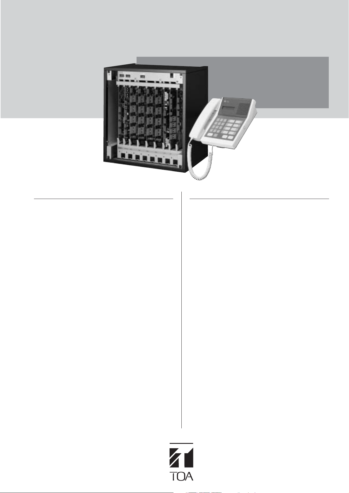
TOA's VS-900 is a security communications system specially
designed for applications in such facilities as office buildings,
factories, schools, hospitals, and prisons. Installed separately
from conventional general-purpose internal communications
systems, the VS-900 can be used to access control or make
urgent calls in emergency situations.
The system is comprised of a central exchange and remote
stations, and permits calls to master stations located in the
central control room or in facility guard rooms from substations
installed in such varied locations as entrance gates, parking lots
or building entrances.
The exchange itself features modular construction that permits
easy customization to fit the desired scale and application, and
later meet changing customer needs by simply plugging in the
corresponding cards. Up to 4 master stations and 64
substations can be connected per exchange, and the system
can be expanded to up to 64 master stations and 1,024
substations through the tie-line connection of up to 16
exchanges.
A standard personal computer can also be connected to the
exchange to provide convenient adjustment of system setting
functions and automatic logging of communication operations.
A full range of exchange functions other than basic
conversation are also featured, including call forwarding, scan
monitoring, emergency conference, conversation recording by
way of external equipment, and paging by way of an external
amplifier.
There are five different types of substations, including those of
indoor-use, outdoor-use, and vandal-resistant types.
The VS-900 can also be used in combination with CCTV,
access control, emergency broadcast systems or other security
equipment to create a more effective security system and
ensure a higher level of safety and security in each facility.
SYSTEM FEATURES
■
System Capacity
• Single Exchange
4 Master stations (enlargement unit: 2)
64 Substations (enlargement unit: 16)
• Up to 16 Exchanges
64 Master stations
1,024 Substations
■
Remote system management via RS-232C port
• PC programming and monitoring software
• Program and maintain multiple exchanges
offsite from one PC (via modem)
■
Audio and Data Logging
• PC archive of all system activity (RS-232C port)
• Record individual Master station and telephone audio
■
Master Station Flexibility
•TOA master with alphanumeric display and clock
• Supports single-line telephone equipment with Caller-ID*
■
Outside Line Communication
• Supports two C/O trunks
• Substation to outside telephone line communication
■
Paging Interface
• 16 control outputs
•1 voice output
■
External Audio Input
•4 activation inputs and 1 audio input for external source
distribution
*in compliance with FCC regulation Part 68.
Page 2
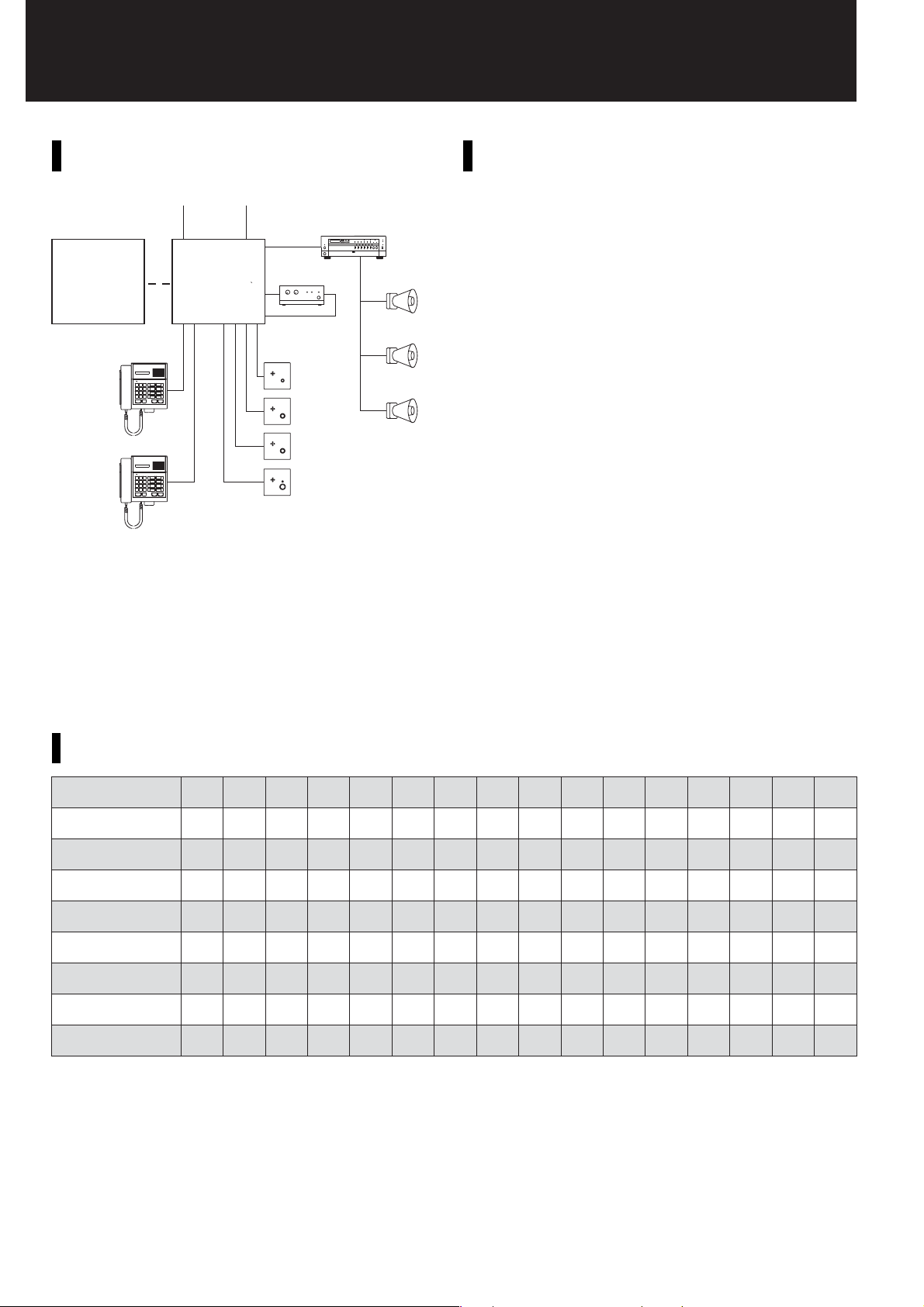
VS-900
Outside line PC (for programming and system maintenance)
VS-900 Exchange VS-900 Exchange
Master stations
* Substation paging needs an external amplifier.
ex:
TOA A-1031 or similar amplifier. Matching transformer such as
the TOA MT-502U needed (Part Number 514-04-013-20).
Substation
paging amplifier*
Substations
SYSTEM CONFIGURATION EXAMPLE
SYSTEM SPECIFICATIONSSYSTEM EXAMPLE
■ Exchange Method: PCM and space division
■ Control Method: Common stored program control
External paging equipment
Amplifier
Speaker
Speaker
Speaker
■ Maximum Cable Length
Exchange to Master station: 1.5km (22AWG)
Exchange to Substation: 800m (22AWG) (RS-190: 1.5km)
Exchange to telephone: less than 500Ω (loop impedance)
Exchange to Exchange: 1.0km (22AWG)
(total extension length)
■ Wiring
Master station: 2 twisted pairs
Substation: 2-core shielded (RS-190: 2 twisted pairs)
Telephone: 1 twisted pair
Exchange to Exchange: 2-core shielded for Data,
2 twisted pairs for Audio (per link)
■ Frequency Response: 300 – 3,400Hz
■ Conversation Method
Substation to Master station: Voice Switch or PTT-activated
talk-back
Master station to Master station: Full-duplex handset
communication
■ Power Requirements
Exchange: AC mains (PU-200) or 24V DC
VS-900DI/VS-910DI: 24V DC
■ Operating Temperature
Exchange and Master station: 0 to 40°C
Substation: –10 to 50°C
SYSTEM CONFIGURATION
Master Stations*
Sub-stations*
VS-900MF
PU-200
VS-900MS/AL
VS-900RS/VS-910RS
VS-900CO
VS-900AF
VS-900TI
1
TOA MS-900 Master Station or analog (DTMF) telephone which complies with the FCC requlation Part 68 (supplied by others).
*
2
*
RS-150, RS-160, RS-170, RS-180, RS-190
1
481216 20 24 28 32 36 40 44 48 52 56 60 64
2
64 128 192 256 320 384 448 512 576 640 704 768 832 896 960 1024
12345678910111213141516
24681012 14 16 18 20 22 24 26 28 30 32
24681012 14 16 18 20 22 24 26 28 30 32
481216 20 24 28 32 36 40 44 48 52 56 60 64
12345678910111213141516
12345678910111213141516
02345678910111213141516
Page 3

VS-900
CONVENIENT FUNCTIONS
CALL-RELATED FUNCTION
GROUP CALL
A designated group of up to 16 master stations or telephones can be
called from any substation, which is answered from any called master
station (telephone).
[System pre-programming]
First, one of master stations (telephones) in a group must be programmed
as a representative station, and the rest as member stations. Then, a
calling substation must be programmed to call the representative station.
TRANSFER-RELATED FUNCTION
CALL TRANSFER
(1) Call transfer
A master station (or telephone) can transfer the conversation partner to
another master station (or telephone).
(2) Call Hold and Call Back
These functions enable the master station (or telephone) to temporarily
put the current conversation on hold (Call Hold), and return to the
original conversation (Call Back) after talking with a third party.
Note: Master station and telephone operation differs.
CALL FORWARDING-RELATED FUNCTIONS
CALL FORWARDING
When away from one's desk, incoming calls can be automatically
forwarded to another receiving station. The receiving station*
be registered at the original station (forwarding station). It is also possible
to active this feature from the destination receiving station.
[System pre-programming]
To use this function, enable the Call Forwarding function in system
programming.
TIME-BASED CALL FORWARDING
All incoming calls to the original station*1 (forwarding station) can be
automatically rerouted to the designated master station*
during a specific period of the day.
[System pre-programming]
(1) To use this function, the Time-Based Call Forwarding function
must be enabled in system programming.
(2) The forwarding interval (start and end times) can be registered
in the system programming. (Registration can only be performed for an
entire exchange. Different times cannot be set for different stations on
the same exchange.)
NO-ANSWER CALL FORWARDING
Calls to the original station*1 (forwarding station) are automatically rerouted
to the designated receiving station*
if the called party does not respond within a preset period of time.
[System pre-programming]
(1) To use this function, the No-Answer Call Forwarding function must be
enabled in system programming.
(2) Register a variable "no-response" time of 1 - 99 seconds (in 1 second
units) in the system programming.
(Registration can only be performed for an entire exchange. Different
times cannot be set for different stations on the same exchange.)
1
BUSY CALL FORWARDING
Calls to a busy station*2 are automatically forwarded to a designated
2
station*
.
[System pre-programming]
To use this function, the Busy Call Forwarding function must be enabled in
system programming.
*1Both the forwarding and receiving stations must be either master stations or
telephones. Calls cannot be transferred to a substation.
2
The station which forwards calls (forwarded station) and the station to which calls
*
are forwarded (receiving station) must be either a master station or a telephone.
Calls cannot be forwarded to a substation.
1
number can
1
(receiving station)
MONITOR-RELATED FUNCTION
SCAN MONITOR
Any master station can scan a designated group of substations for audio
monitoring of each substation.
[System pre-programming]
(1) Substations to be monitored (up to 16) can be registered for each
master station in system programming.
(2) Monitor interval times of 1 - 99 seconds (in 1 second units) for each
master station can be registered in the system programming.
PAGING-RELATED FUNCTIONS
ZONE PAGING
Per mits paging to up to 19 individual zones (01 – 19) established by
combining multiple substations with external public address system
equipment. Two or more individual zones can simultaneously be selected.
[System pre-programming]
(1) The number of zone number digits (1 or 2 digits) can be registered in
system programming.
Single digit: Zone Nos. 1 - 9
Double digit: Zone Nos. 01 - 19
(2) Substation numbers and selective external public address equipment
outputs to be included in each zone can be registered in the system
programming. Up to 1,024 substations and up to 16 selective outputs
can be registered per zone.
Note: Only 1 voice output is made available for paging to external equipment. It is
impossible for 2 or more persons to simultaneously initiate paging.
ALL-ZONE PAGING
Paging calls can be simultaneously made to substations and external
public address equipment in the all programmed zones. (Paging calls are
not made to substations and external public address equipment not
assigned to zones.)
[System pre-programming]
(1) The number of digits (1 or 2) of an all-zone paging access number ([0]
or [0][0]) can be registered in system programming.
(2) Substation numbers and selective external public address equipment
outputs to be included in each zone can be registered in the system
programming. Up to 1,024 substations and up to 16 selective outputs
can be registered per zone.
EMERGENCY PAGING
Paging calls can be made to all connected master stations, substations,
and external public address equipment simultaneously.
[System pre-programming]
Master stations that can place Emergency Paging calls must be registered
in the system programming.
EXTERNAL SOURCE DISTRIBUTION
By activating the input, external sound sources can be distributed to preprogrammed paging zones.
Per mits source distribution to up to 19 individual zones (01 - 19)
established by combining multiple substations with external public address
system equipment. Two or more individual zones can simultaneously be
selected.
[System pre-programming]
Up to 9 (19) paging zones can be registered for each activation input (up to
4 inputs) in system programming.
(Up to 1,024 substations and up to 16 selective external public address
equipment outputs to be included in each zone are registered in the Zone
Paging system programming.)
PAGING TIME-OUT
Paging calls that exceed a set time limit are automatically terminated. (This
function is used mainly to prevent the line from being occupied because
the user forgot to turn off the function.) The Time-Out function is disabled
when an emergency paging call is placed.
[System pre-programming]
• Program whether to [Enable] or [Disable] the Paging Time-Out function.
• Paging time-out (10 - 990 seconds in 10 second units) common to both
Individual Zone and All-Zone Paging functions can be registered in the
system programming.
PAGING REDIAL
This function permits redialing the last-paged zone by simple key
operations.
Page 4
VS-900
TELEPHONE-RELATED FUNCTIONS
OUTGOING TELEPHONE CALLS
Outside telephone lines can be connected to the VS-900 system,
permitting the system's master stations to make or receive outside line
telephone calls.
[System pre-programming]
A single-digit outside line access number ([0]-[9]) must first be
programmed.
INCOMING OUTSIDE LINE CALLS (DIRECT-IN LINE)
When an outside telephone call is received, a call tone sounds at the
registered representative station* and up to 3 member stations*.
[System pre-programming]
One representative station* and up to 3 member stations* must be
registered in the system programming to receive outside line calls.
* Both the representative and member stations must be master stations or
telephones.
Note: Both the representative and member stations must be connected to the same
exchange connected to the outside telephone line.
INCOMING OUTSIDE LINE CALLS (DIRECT-IN DIALING)
Outside line calling parties can be connected to a desired master station
(telephone) or substation by directly dialing the station number.
OUTSIDE LINE CONNECTION TIME-OUT
• The duration of connection with the outside line telephone can be limited
to automatically terminate conversations.
• When the limited time is reached, a warning signal tone is transmitted to
both the calling and called parties to terminate the conversation.
[System pre-programming]
(1) Program whether to [Enable] or [Disable] the Connection Time-Out
function.
(2) Set a connection time limit of 1 – 99 minutes in 1 minute unit.
OUTSIDE LINE CONVERSATION RECORDING
• Connecting an external recording device permits recording of outside line
telephone conversations.
• The external control output is made when the outside line telephone is
connected, and is broken when the telephone is disconnected.
CONVENIENT FUNCTIONS
OUTSIDE LINE CALL FORWARDING
All calls can be automatically rerouted to the designated receiving
telephone by registering the outside line access number at the original
master station or telephone.
[System pre-programming]
(1) To use this function, the Call Forwarding function must be enabled in
system programming.
(2) The receiving telephone number can individually be registered for each
master station (or telephone) in the system programming.
TIME-BASED OUTSIDE LINE CALL FORWARDING
All incoming calls to the original master station or telephone can be
automatically rerouted to the designated outside line telephone during a
specific period of the day.
[System pre-programming]
(1) To use this function, the Call Forwarding function must be enabled in
system programming.
(2) Register the receiving outside line telephone number individually for
each master station (or telephone) in the system programming.
(3) The forwarding interval (start and end times) can be registered in the
system programming. (Registration can only be performed for an entire
exchange. Different times cannot be set for different stations on the
same exchange.)
CONFERENCE-RELATED FUNCTIONS
THREE-PARTY CONFERENCE (INDIVIDUAL CALL
CONFERENCE)
Any master station (or telephone) can individually call other master
stations (telephones) to hold a 3-party conference.
EMERGENCY CONFERENCE
To enable conferences among up to 4 parties in emergency situations,
master stations or telephones can call other registered master stations or
telephones with a simple operation.
[System pre-programming]
To use this function, up to 3 master stations or telephones must be
individually assigned to each master station in the system programming.
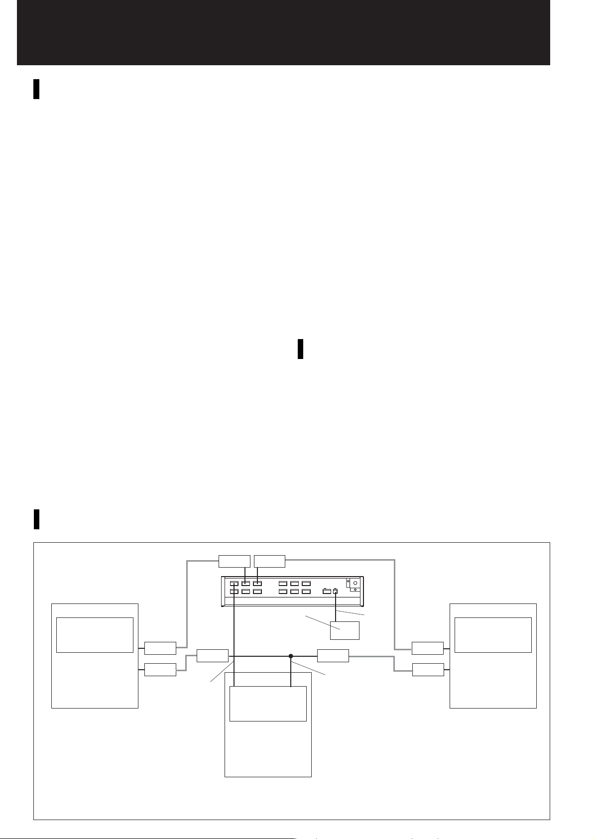
VS-900 OPTICAL LINK CONNECTION EXAMPLE (useing VS-900SC)
Fiber optic cable Fiber optic cable
VS-900TI
Tie-Line unit
O.A.L. O.A.L.
O.A.L.
O.D.L. O.D.L.
O.D.L. O.D.L.
VS-900MF
Audio signal line
* O.A.L. (Optical Analog Link): Optical/audio signal converter
O.D.L. (Optical Data Link):
Optical/digital signal converter
O.A.L.
PU-200
Power
Transformer
unit
VS-900TI
Tie-Line unit
VS-900MF
VS-900SC
Power
supply
Control signal line
VS-900TI
Tie-Line unit
VS-900MF
Page 5

VS
MF
Note:
Photo shows Main Fame with card modules installed.
-900
Main Frame
420
466.6
483.6
101.6
37.8 101.6164.9
443.7
288.3
Card modules installed here. Includes 2 RS-232C ports.
SPECIFICATIONS
Power Source
Current Consumption
Speech Path Configuration
Serial Port
Installation Method
Other
Connection Terminals
Operating Temperatures
Finish
Dimensions
Weight
Accessories
20V AC, 24V DC
5.5A
Time sharing switch (T1 stage)
Serial Port complies with the
RS-232C Standard, D-sub connector
(9-pin, female), 2 ports
Rack- and wall-mountable
Real time clock for time control, Unit's presence/
non-presence detection, System programming
data maintenance, Power switch
Bus connector:
DIN connector (64-pin, female) × 9
PU-200 connection terminal:
4-pin × 2 (2 PU-200s are connectable)
24V DC input terminal:
4-pin (with grounding terminal)
0°C to +40°C
Pre-coated steel plate, black, 30% gloss
483.6 (W) × 443.7 (H) × 288.3 (D)mm
12.7kg
Rack mounting bracket × 2, Rack
mounting screw × 8, Fibber washer × 8,
Mounting screw × 6, Cable clip × 20,
Floppy disk (PC setting software) × 1.
CR2032 battery × 1, Connector (4-pin) × 3
VS-900MS
VS-900AL
Master Station Interface Card
For connecting up to two master stations per card.
An external recording device can be connected to each line.
SPECIFICATIONS
Power Source
Current Consumption
Supply Power
Number of Lines
Conversation Recording
Line 1
for master station
Line 1
Recording
Line 2
for master station
Line 2
Recording
HOT
Voice Output
GND
HOT
GND
Control Output
HOT
Voice Output
GND
HOT
GND
Control Output
144
Output
305
Option
Connection Terminals
Operating Temperatures
Weight
Accessories
Telephone Interface Card
For connecting up to two telephones per card.
An external recording device can be connected to each line. Use
the telephone which complies with the FCC regulation Part 68.
5V DC, 24V DC (supplied from the main
frame)
50mA (5V DC), 200mA (24V DC)
24V DC, 80mA
2 lines
Voice output: 0dB*, unbalanced
Control output: Open collector output,
withstand voltage: 24V DC, control
current: 20mA
Master station connection monitoring
function
Main frame connection side:
DIN connector (64-pin, male)
Line output: 4-pin × 2
Recording voice/control output: 4-pin × 2
0°C to +40°C
350g
Connector (4-pin) × 4, Ferrite clamp × 2
* 0 dB = 1V
Line 1
for telephone
Line 1
Recording
Line 2
for telephone
Line 2
Recording
HOT
Voice Output
GND
HOT
GND
Control Output
HOT
Voice Output
GND
HOT
GND
Control Output
144
305
Unit: mm
SPECIFICATIONS
Power Source
Current Consumption
Supply Power
Number of Lines
Conversation Recording
Output
Selective Signal Type
Monitoring Function
Applicable Terminal
Control Function
Connection Terminals
Operating Temperatures
Weight
Accessories
5V DC, 15V DC, 24V DC (supplied from
the main frame)
150mA (5V DC), 30mA (15V DC), 200mA
(24V DC)
24V DC, 80mA
2 lines
Voice output: 0dB*, unbalanced
Control output: Open collector output,
withstand voltage: 24V DC, control
current: 20mA
DTMF signal
Line loop detection function
Telephone sets to comply with FCC Part 68
Call signal transmission,
Audible signal transmission,
Caller identification signal transmission
(Caller ID Function)
Main frame connection side:
DIN connector (64-pin, male)
Line output: 2-pin × 2
Recording voice/control output: 4-pin × 2
0°C to +40°C
400g
Connector (2-pin) × 2, Connector (4-pin) ×
2, Ferrite clamp × 2
* 0 dB = 1V
Page 6

VS-900CO
Outside Line Interface Card
Connects up to two outside lines per card.
An external recording device can be connected to each line.
SPECIFICATIONS
Power Source
Current Consumption
Number of Lines
Conversation Recording
Line 1
Line 1
Recording
Line 2
Line 2
Recording
Outside Line
GND
GND
HOT
Voice Output
GND
HOT
GND
Control Output
Outside Line
GND
GND
HOT
Voice Output
GND
HOT
GND
Control Output
144
Output
305
Selective Signal Type
Signal Format
Main Functions
Connection Terminals
Operating Temperatures
Weight
Accessories
5V DC, 15V DC, 24V DC (supplied from
the main frame)
300mA (5V DC), 50mA (15V DC), 50mA
(24V DC)
2 lines
Voice output: 0dB*, unbalanced
Control output:
withstand voltage: 24V DC, control
current: 20mA
Open collector output,
DTMF signal
Loop start and Ground start compatible
DTMF dial signal transmission function,
DTMF signal detection function, call signal
(receiving) detection
Main frame connection side:
DIN connector (64-pin, male)
C/O line connection side: 4-pin × 2
Recording voice/Control output: 4-pin × 2
0°C to +40°C
380g
Connector (4-pin) × 4
* 0 dB = 1V
VS-900AF
VS-900TI
Audio Function Card
HOT
GND
Voice Input
HOT
Control Input 1
GND
HOT
GND
Control Input 2
HOT
Control Input 3
GND
HOT
GND
Control Input 4
HOT
GND
Voice Output
Control Output 1
Control Output 2
Control Output 5
Control Output 6
Control Output 9
Control Output 10
Control Output 13
Control Output 14
HOT
HOT
Control Output 3
GND
GND
HOT
HOT
GND
Control Output 4
GND
HOT
HOT
Control Output 7
GND
GND
HOT
HOT
GND
Control Output 8
GND
HOT
HOT
Control Output 11
GND
GND
HOT
HOT
GND
Control Output 12
GND
HOT
HOT
Control Output 15
GND
GND
HOT
HOT
GND
Control Output 16
GND
144
Tie-Line Interface Card
Enables conference, external amplifier paging and external
source distribution functions.
SPECIFICATIONS
Power Source
Current Consumption
Paging Output
305
External Source
Distribution
Conference Link
Connection Terminals
Operating Temperatures
Weight
Accessories
5V DC, 15V DC, 24V DC (supplied from
the main frame)
100mA (5V DC), 50mA (15V DC), 30mA
(24V DC)
Voice output: 1 output, 0dB*, unbalanced
Control output: 16 outputs, open collector
output, withstand voltage:
24V DC, control current: 20mA
Voice input: 1 input, 0dB*, unbalanced
Control input: 4 inputs, no-voltage make
contact, open voltage: 24V DC, short
circuit current: 20mA
1 link (up to 4-party conference)
Main frame connection side:
DIN connector (64-pin, male)
External interface side:
Voice output 2-pin
Control output 2-pin × 16
Voice input 2-pin
Control input 2-pin × 4
0°C to +40°C
230g
Connector (2-pin) × 2,
Connector (4-pin) × 10
* 0 dB = 1V
Voice line 1
Voice line 2
Voice line 3
Voice line 4
Data line
RS–485
Interconnects multiple exchanges. Connects up to 4 links
using one pair of data lines and two pairs of voice lines.
SPECIFICATIONS
Power Source
Current Consumption
Number of Audio Links
HOT
COM
HOT
COM
HOT
COM
HOT
COM
HOT
COM
HOT
COM
HOT
COM
HOT
COM
A
B
GND
GND
Connection Format
Transmitting System
Input/Output Level
305
Other
Connection Terminals
144
Operating Temperatures
Weight
Accessories
5V DC, 15V DC (supplied from the main
frame)
100mA (5V DC), 50mA (15V DC)
4 links
Multidrop system
Data: RS-485
Voice: Base band
Voice: 0dB*, balanced
Data: In compliance with RS-485
Standard
Exchange number setting function
Main frame connection side:
DIN connector (64-pin, male)
Tie-line interface side:
4-pin × 4 (Voice line)
4-pin × 1 (Data line)
0°C to +40°C
320g
Connector (4-pin) × 5
* 0 dB = 0.775V
Page 7

VS-900RS
Substation Interface Card
Line 1
for Substation
Line 2
Line 5
Line 6
Line 9
Line 10
Line 13
Line 14
A
B
C
A
B
C
A
B
C
A
B
C
A
B
C
A
B
C
A
B
C
A
B
C
HOT
Voice Output
GND
HOT
GND
Control Output
A
B
Line 3
C
A
B
Line 4
C
A
B
Line 7
C
A
B
Line 8
C
A
B
Line 11
C
A
B
Line 12
C
A
B
Line 15
C
A
B
Line 16
C
305
144
For External
Paging Amplifier
* for RS-150/RS-160/RS-170/RS-180
Connects up to 16 substations per card. Equipped with two
speech links, one link able to be used as a paging link with
the paging input/output connected to an external amplifier.
SPECIFICATIONS
Power Source
Current Consumption
Number of Lines
Number of Links
Paging Output
Paging Input
Conversation Method
Supply Power
Other
Connection Terminals
Operating Temperatures
Weight
Accessories
5V DC, 24V DC (supplied from the main
frame)
5V DC: 200mA, 24V DC: 600mA
Substation 16 lines
2 links (one of 2 links is also used as a
Paging Link.)
Unbalanced, –20dB signals to be sent to
a paging amplifier.
Balanced, acceptable signal on the 25V
line output from a paging amplifier.
Half-duplex conversation by voice-
operated switch or simplex conversation
by PTT switch
Maximum 1W per substation
Call button detection function and speech
link control function
Main frame connection side:
DIN connector (64-pin, male)
Substation connection side:
Tw o-core shielded cable (3-pin) × 16
Paging output/paging input: 4-pin
0°C to +40°C
550g
Connector (3-pin) × 16,
Connector (4-pin) × 1
VS-910RS
Substation Interface Card
For RS-190
Line1
Line3
Line5
Line7
Line9
Line11
Line13
Line15
A
A
B
B
C
Line2
C
D
D
A
A
B
B
C
Line4
C
D
D
A
A
B
B
C
Line6
C
D
D
A
A
B
B
C
Line8
C
D
D
A
A
B
B
C
Line10
C
D
D
A
A
B
B
C
Line12
C
D
D
A
A
B
B
C
Line14
C
D
D
A
A
B
B
C
Line16
C
D
D
305
144
* for RS-190 (Full-Duplex Substation)
The VS-910RS Substation Interface Card is used to connect
the Full-Duplex Substation by way of 2 sets of twisted pair
cables. Up to 16 Full-Duplex Substations can be connected
per card. The VS-910RS has 2 speech paths, either of which
can be used for substation paging.
SPECIFICATIONS
Power Source
Current Consumption
Number of Lines
Number of Links
Coversation Method
Audio Output
Supply Power
Control System
Connection Terminals
Connection Monitoring
Function
Operating Temperatures
Weight
Accessory
Maxmum cable distance
Cable Type
Distance
5V DC, 24V DC (supplied from the main
frame)
5V DC: 200mA
24V DC: 600mA
(maximum during nomal use),
1.5A
(maximum when 16 lines are
simultaneusly shorted)
Substation 16 lines
2 links (one of 2 links is also used as a
Paging Link.)
Full-duplex conversation or Half-duplex
conversation by voice-operated switch
Maximum 1W per substation
Maximum 20V/30mA per substation
Two-way dial pulse width system (call,
restoration, external control, etc.) by current loop
Main frame connection side:
DIN connector (64-pin, male)
Substation connection side: 4-pin × 16
Line connection detection, line short
circuit/open circuit/failure detection and
communication irregularity detection
0°C to +40°C
700g
Connector (4-pin) × 1
AWG24 AWG22 AWG20
(ø0.52mm) (ø0.65mm) (ø0.82mm)
1km 1.5km 2km
* 0 dB = 1V
Unit: mm
Page 8

MS-900
Master Station
MS-900 can make calls to or receive calls from the
substation or the master station (telephone).
Rear panel
216
208
213
74.5
69.5
83.521
80.5
94
Wall mounting bracket
Wall mounting bracket
5.5
Dimensional diagram for mounting
the attached wall mounting bracket
60
125
MS-900
8.5
SPECIFICATIONS
Power Source
Current Consumption
Talk System
Talk Frequency
Handset
Microphone/Speaker
Handsfree Microphone
Station Speaker
Key Pad
Display
Auto Dialing Key
Station Speaker Volume
Control
Handset Speaker
Volume Control
Installation Method
Wiring
Connection Terminals
Operating Temperatures
Finish
Dimensions
Weight
Accessories
24V DC (supplied from the main frame)
60mA
Duplex or semi-duplex conversation
300 to 3.400Hz
Dynamic type, 150Ω
Electret condenser microphone
Dynamic type, 8Ω, ø57mm, 0.6W
Membrane switch
12 digits LCD
8 keys
2-step selection slide switch
Volume, 0 to +12dB
Desk-/wall-mountable
Twisted pair cables/2-pair
Line output:
6-position 4-contact modular jack
External speaker output:
2-pin screw terminal (8Ω/0.6W)
0°C to +40°C
ABS resin, pale white
216 (W) × 74.5 (H) × 213 (D)mm
940g
Wall mounting bracket × 1, Connection
cord (3m) × 1, Wood screw × 2
RS-150
RS-160
Substation (Indoor Type)
SPECIFICATIONS
Rated Input
Rated Impedance
Output Sound Pressure
Level
Frequency Response
Internal Speaker
Call Switch Button
Operating Temperatures
Finish
Dimensions
Weight
Accessories
120
2
120
83.5
46
90
43.5
48.5
Black (C)
Brown (B)
Orange (A)
Substation (Indoor Vandal-Resistant Type)
SPECIFICATIONS
Rated Input
Rated Impedance
Output Sound Pressure
Level
Frequency Response
Internal Speaker
Call Switch Button
Operating Temperatures
Finish
Dimensions
Weight
Accessories
46
120
90
83.5
120
3
52.5
57.5
Weatherproof coating
Black (C)
Brown (B)
Orange (A)
1W
625Ω (1W/25V)
82dB
300 to 4,000Hz (minimum 72dB)
4cm dynamic
Resin-made push button
–10°C to +50°C
(Temperature range not to freeze the
speaker and switch)
Stainless steel (SUS304), hairline
120 (W) × 120 (H) × 48.5 (D)mm
410g
Oval head screw × 4
1W
625Ω (1W/25V)
82dB
300 to 4,000Hz (minimum 72dB)
4cm dynamic
Metal push button
–10°C to +50°C
(Temperature range not to freeze the
speaker and switch)
Stainless steel (SUS304), hairline
120 (W) × 120 (H) × 57.5 (D)mm
540g
Oval head screw × 4
Page 9

RS-170
rear
Substation (Outdoor Vandal-Resistant Type)
SPECIFICATIONS
Rated Input
Rated Impedance
Output Sound Pressure
Level
Frequency Response
Internal Speaker
Call Switch Button
Weather-Resistant
Coating
Operating Temperatures
Finish
Dimensions
Weight
Accessories
120
3
120
83.5
46
90
52.5
57.5
Black (C)
Brown (B)
Orange (A)
1W
625Ω (1W/25V)
82dB
300 to 4,000Hz (minimum 72dB)
4cm dynamic
Metal push button
Printed circuit board
–10°C to +50°C
(Temperature range not to freeze the
speaker and switch)
Stainless steel (SUS304), hairline
120 (W) × 120 (H) × 57.5 (D)mm
540g
Oval head screw × 4
RS-180
rear
RS-190
Substation (Outdoor Vandal-Resistant Type with Control Output)
SPECIFICATIONS
46
120
90
83.5
120
3
52.5
57.5
Black (C)
Brown (B)
Orange (A)
White(Open
collector: Hot)
Blue(Open
collector: COM)
Weatherproof coating
Rated Input
Rated Impedance
Output Sound Pressure
Level
Frequency Response
Internal Speaker
Call Switch Button
Call LED
Control Output
Weather-Resistant
Coating
Operating Temperatures
Finish
Dimensions
Weight
Accessories
1W
625Ω (1W/25V)
82dB
300 to 4,000Hz (minimum 72dB)
4cm dynamic
Metal push button (red top: ø20)
Red
Open collector output: 24V DC, 5mA
(The open collector output is kept turned
on till the conversation is finished after the
call button was pressed.)
Printed circuit board
–10°C to +50°C
(Temperature range not to freeze the
speaker and switch)
Stainless steel (SUS304), hairline
120 (W) × 120 (H) × 58.5 (D)mm
570g
Oval head screw × 4
Full-Duplex Substation (Indoor Type with Control Output)
46
120
85
83.5
120
2
58.5
SPECIFICATIONS
Rated Input
Rated Impedance
Internal Speaker
72.1
53
Control Output
Operating Temperatures
Finish
Dimensions
Weight
Accessories
Maxmum cable distance
Cable Type
Distance
1W
500Ω
4cm cone-type
Open collector output: 24V DC, 30mA
(The open collector output is kept turned
on till the conversation is finished after the
call button was pressed.)
–10°C to +50°C
(Temperature range not to freeze the
speaker and switch)
Panel: Stainless steel (SUS304), hairline
Call button: Resin
120 (W) × 120 (H) × 58.5 (D)mm
465g
Box mounting screw (No.6–32UNC × 8) × 4,
Box mounting screw (M4 × 25) × 4
AWG24 AWG22 AWG20
(ø0.52mm) (ø0.65mm) (ø0.82mm)
1km 1.5km 2km
RS-191
Option Handset
116
115
70
48
220
Unit: mm
SPECIFICATIONS
Handset Receiver
Handset Transmitter
Internal Speaker
Operating Temperatures
Finish
Dimensions
Weight
Accessories
Dynamic type
Electret condenser type
4cm cone-type
0°C to +40°C
(Temperature range not to freeze the
speaker and switch)
ABS resin, pale white
116 (W) × 220 (H) × 70 (D)mm
330g
Box mounting screw (No.6–32UNC × 8) × 4,
Box mounting screw (M4 × 25) × 4
46
83.5
Page 10

V
S
-900DI*
305
139.5
6.4
133.4
6–ø4
Direct Select Control Card
SPECIFICATIONS
Power Source
Maximum Cable Length to
Exchange
Maximum Number of
Connectable VS-900DI Cards
Function Key Input
Communication Line
In-use Indication Output
Electret Microphone Input
Speaker Output
Headset Connection
144
6.41.8
16.5
PC Interface
Usable Cable
Operating Temperatures
Weight
Accessories
24V DC, 1A
1.5km (including the additional master station line from the VS-900DI) when
the cable gauge is AWG22
4 cards per exchange, 64 cards per system (16 tie-lined exchanges)
One each of (C), (PTT), (XFER) and (TEST), keys, Dry contact, 8-pole
screwless terminal
Dry contact, 5V DC/0.5mA
Contact resistance: 50Ω or less
1 line for VS-900 exchange (VS-900MS card) and 1 line for MS-900 master
station, 16-position 4-contact modular jack for each line
Open collector output, 24V DC/ approx. 100mA, 2-pole screwless terminal
Microphone sensitivity: –75 to –65dB*, phantom power supply (power supply
can be cut off), 2-pole screwless terminal
Speaker impedance: 8Ω
Output terminal: 2-pole screwless terminal
Microphone sensitivity: –75 to –65dB*
Speaker impedance: 200 to 400Ω
Detection jack contact input (Det.): 5V DC, 10mA
Contact resistance:10Ω or less, 8-pole screwless terminal (Headset can also
be turned on/off using the manual switch instead of the jack contact input.)
RS-232C D-sub connector (9 poles, female type)
Bared-core length: 5 to 6mm
Cross section area: 0.14 to 2.5mm
0°C to +40°C
350g
Ferrite clamp × 2, Modular cord (3m) × 1
2
* 0 dB = 1V
VS-910DI*
305
139.5
6.4
133.4
6–ø4
144
6.4
100
Direct Select I/O Card
SPECIFICATIONS
Power Source
Maximum Number of
VS-910DIs per VS-900DI
Maximum Number of Ports
per VS-910DI
Maximum Number of Ports
per Full VS-910DI-Mounted
System
Switch Input
Open Collector Output
Relay Output
82.8
74.9
51.816
2.159
15 or less1.6
Operating Temperatures
Weight
15.5 or less
24V DC, 1A
32
32 switch inputs (for calling and response switch operation)
32 open collector outputs (for LED indication of incoming and outgoing calls)
32 relay outputs (call-or response-activated relay output)
1024 switch inputs (for calling and response switch operation)
1024 open collector outputs (for LED indication of incoming and outgoing calls)
1024 relay outputs (call-or response-activated relay output)
32 inputs (for custom-made direct select key operation for calling or response)
dry contact, 5V DC, 0.5mA
Contact resistance: 50Ω or less, 50-pole "CHAMP®" IDC connector
(Amphenol connector)
32 outputs (for LED indication of incoming and outgoing calls)
24V DC, approx. 100mA, 50-pole "CHAMP®" IDC connector
(Amphenol connector)
32 relay outputs, call-or response-activated relay output, normal open,
24V DC, 1A, 50-pole "CHAMP®" IDC connector (Amphenol connector)
0°C to +40°C
460g
* The VS-900DI Direct Select Control Card and VS-910DI Direct
Select I/O Card are interface cards that connect to the VS-900
Exchange to enable calling-station indication output, direct select
input, and external equipment control output functions.
PU-200
Power Transformer Unit
160
140
120
10
ø
18
4
Fitting Hole
SPECIFICATIONS
Power Source
Output Voltage
Output Current
178
Finish
Dimensions
Weight
Accessories
115
145
165
65
68
NCU Type: 110V/120V AC, 50/60Hz
SEM Type: 220V/230V AC, 50/60Hz
20V AC
2.5A
Color steel plate, ivory
160 (W) × 68 (H) × 178 (D)mm
2.8kg
Mounting brackets × 2
Fuse (250V, 2A) × 1
Fuse (125V, 4A) × 2
Round head wood screw (3.5 × 25) × 4
Page 11

VS
SC
-900
Site Connector
482
465
420
(without front panel)
238
236
TOA's VS-900SC Site Connector is used to connect the VS-900
system exchanges to the fiber optical interface.
SPECIFICATIONS
76.2
4-6×10
Power Source
Number of Links
Input
88.4
Output
Installation Method
Connection Terminal
Operating Temperatures
Finish
Dimensions
Weight
Accessories
20V AC (supplied from the power
transformer unit, under 250mA)
24V DC
4 links
0dB*, 600Ω, balanced (transformer)
0dB*, 600Ω, balanced (transformer)
Rack- and wall-mountable
Voice line side: 4-pin × 3 (voice line)/1 link
PU-200 connection terminal: 2-pin
24V DC input terminal: 4-pin
–10°C to +40°C
Panel, Case: Pre-coated steel plate, black
420 (W) × 88.4 (H) × 238 (D)mm
3.55kg
Rack mounting bracket × 4, Rack mounting
screw × 4, Fiber washer × 4, Wall mounting
bracket × 2, Wall mounting screw (4.1 × 20) × 4,
Link Plate*2 × 2, Link plate fixing screw × 2,
Bracket mounting screw × 8, Connector (4-pin)
× 13, Connector (2-pin) × 1
* 0 dB = 1V
*2
Enables to link VS-900SC with VS-900MF
PN-100B
YC-303
Main Frame Wall Mounting Bracket
Rack Mount Panel for PU-200
SPECIFICATIONS
10
4–7x10.5
177
101.637.7
466
483
290
338
391.4
Main frame VS-900MF
99200
440
SPECIFICATIONS
58
Mounting Capacity
Finish
Dimensions
Weight
Finish
Dimensions
Weight
Accessories
Up to 2 PU-200s
Color steel plate, Black
483 (W) × 177 (H) × 10 (D)mm
0.7kg
Steel, Black, electrodeposition paint
391.4 (W) × 440 (H) × 58 (D)mm
2.1kg
Main frame mounting screw × 4,
Wall mounting screw × 4
YC-302
36.2 78 787866
Back Box (2-gang) for RS-150/160/170/180/190
1–M4
46
92
106
73
13
83.5
106
3–ø21.5
knock-out hole
4–ø27.1
knock-out hole
Outlet Box
2–ø27.1
knock-out
hole
2–M4102
4–ø21.5
knock-out hole
SPECIFICATIONS
Quantity packed per
display carton
Finish
10244
Dimensions
Weight
10 pieces
SPHT, MFZn4 (glazed chromate)
Outlet box: 102 (W) × 102 (H) × 44 (D)mm
Cover: 106 (W) × 106 (H) × 13 (D)mm
370kg
Unit: mm
Page 12

PC INTERFACE SOFTWARE
DESCRIPTION
Conversation and broadcasting functions can only be used by
programming individual line assignments for each facility, station
numbering schedules, function details and other data into the
exchange before the system is actually used. To perform such
settings, a personal computer loaded with dedicated software
needs to be connected to the exchange. This dedicated software
enables general control and maintenance settings as well as
system programming functions.
Notes
Some functions to be registered at master stations cannot be enabled without prior
system programming.
SYSTEM REQUIREMENTS
OS: Microsoft
CPU: Pentium® 200MHz or more
Memory: 64MByte or more
Hard disk: Free space of 50MByte or more
Monitor: Larger than 14.1 inches
Resolution: 640 × 480 pixel, 256 colors or more
®
Windows 2000
Windows NT® Workstation 4.0 Service Pack 5/
®/
Windows XP
®
SYSTEM PROGRAMMING (SETTING ITEMS)
System Setting
• Number of Exchanges
• Station Number Digit
• Tie-Line Connections
• Exchange Station Number Assignment
Line Setting
(1) Master station/telephone setting
Registers the following contents designating the exchange number
(1 - 16 or ALL).
• Station Number
• Station Name
• Access to Outgoing Calls
• Emergency Paging
• "Outside Line Call Forwarding" Receiving Telephone Number
• "Call Forwarding" Receiving Station*
• "Time-Based Call Forwarding" Receiving Station*
• "Busy Call Forwarding" Receiving Station*
• "No-Answer Call Forwarding" Receiving Station*
* This setting can be performed at the master station as well.
(2) Substation setting
Registers the following contents designating the exchange number
(1 - 16 or ALL).
• Station Number
• Station Name
• Called Station Exchange Number
• Called Station Line Number
• Called Station Number
• Called Station Name
• Call Priority
(3) Outside line setting
Registers the following contents designating the exchange number
(1 - 16).
• Outside Line Connection Time-Out
• Outside Line Name
• Outgoing Call Access Number
• Direct-In Dialing
• Direct-In Line
• Receiving Station
Function Setting
(1) Group call setting
Registers the following contents designating the representative master
station/telephone.
• Member Station Exchange Number
• Member Station line Number
(2) Call forwarding & time-out settings
Registers the following contents designating the exchange number (1 - 16).
• Call Forwarding
• Time-Based Call Forwarding
• Time-Based Call Forwarding Start Time
• Time-Based Call Forwarding End Time
• Busy Call Forwarding
• No-Answer Call forwarding
• Call Time-Out
• Conversation Time-Out
(3) Scan monitor setting
Registers the following contents designating the master station.
• Monitoring Time
• Monitoring Substation Exchange Number
• Monitoring Substation Line Number
• Monitoring Substation Number
• Monitoring Substation Name
(4) Paging setting
Registers the substations assigned to the zone designating the exchange
number (1 - 16).
• Zone Number Digit
• Paging Time-Out
• Zone
(5) Public address system setting
Registers the control outputs assigned to the zone designating the
exchange number (1 - 16).
• Zone
(6) External source distribution setting
Registers zones to the control input designating the exchange number
(1 -16).
• Zone
(7) Emergency conference setting
Registers the following contents designating the master station.
• Member Station Exchange Number
• Member Station Line Number
• Member Station Number
• Member Station Name
(8) Direct select setting (Relay output from the VS-910DI card)
Registers the following contents designating the exchange number (1 - 16).
• Control Output Mode
MAINTENANCE/CONTROL FUNCTIONS
(1) Remote Dialing
Dialing operations can be remotely performed from a PC instead of the
master Station by designating the exchange and master station
number.
(2) Log Data
The operating log of each exchange can be read, printed out or stored
on hard disk.
(3) Upload/Download
Data can be transmit or received.
(4) Print Out
The exchange setting contents are print out.
(5) PC Port Setting
Setting are made for the connection method and COM port between PC
and exchange.
TOA Corporation
URL : http://www.toa.jp/
Specifications are subject to change without notice.
Printed in Japan (0310) 833-63-161-5A U
 Loading...