

Page 1
INSTALLATION MANUAL
SWITCH PANELS
OPTION HANDSET
RS-140, RS-143, RS-144
RS-141
1. GENERAL DESCRIPTION
The RS-140, RS-143, and RS-144 are substations to be connected to the 2-Core Shielded Substation Interface
Unit. The RS-141, designed exclusively for indoor-use in combination with the RS-140, RS-143, or RS-144, is an
option handset to make handset conversations.
For operation of the units, refer to the N-8000 series instruction manual.
Warning
This is a class A product. In a domestic environment this product may cause radio interference in which case
the user may be required to take adequate measures.
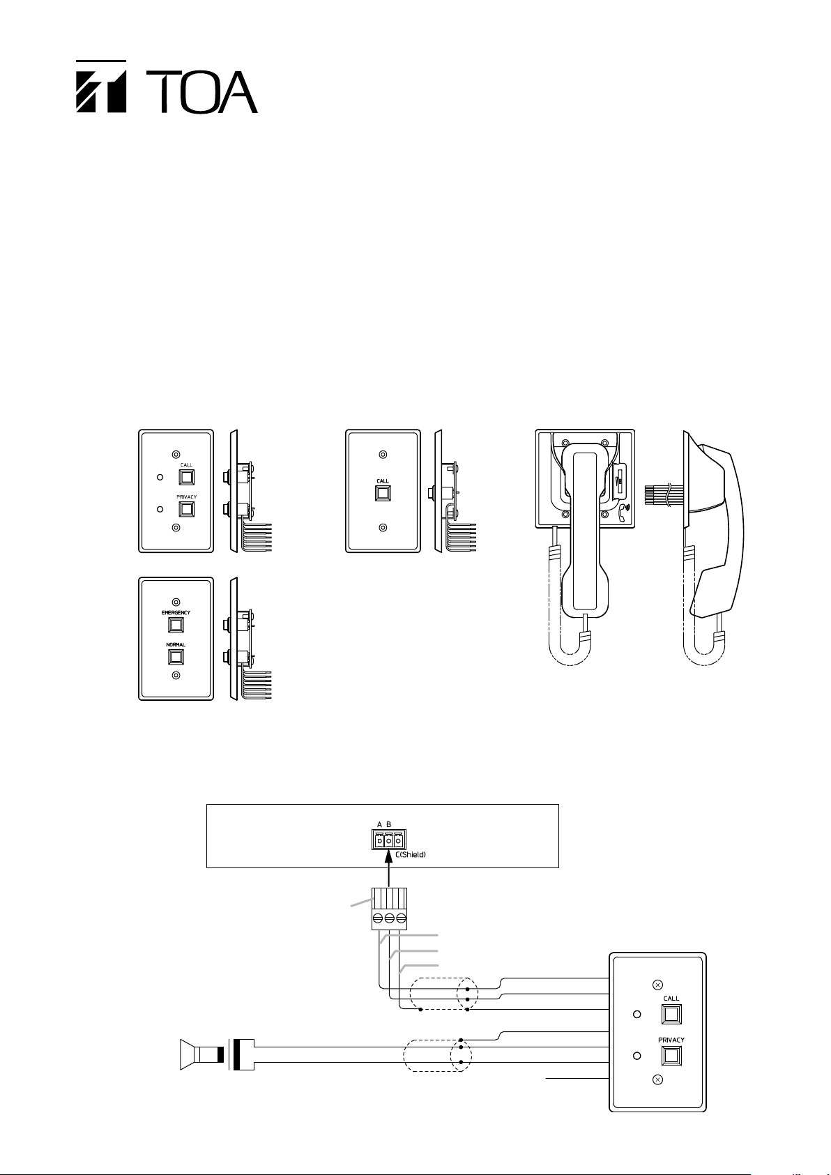
2. APPEARANCE
[RS-140] [RS-143]
[RS-141]
[RS-144]
3. CONNECTIONS
3.1. Switch Panel Connections (When the Option Handset is not used)
Substation interface unit
To the substation connection terminal
3P removable terminal plug
(supplied with the Substation
interface unit)
Note
Cut out the unused Wire (purple) to
avoid short-circuiting.
High-impedance speaker
(Impedance: 600 Ω or more)
Green (HOT)
Blue (COM)
2-core shielded cable
2-core shielded cable
Brown
Red
Orange
Brown (A)
Red (B)
Orange (C)
Yellow (C+)
Green (B+)
Blue (A+)
Purple (H)
N.C.
Switch panel
(Figure shows the RS-140.)
Page 2
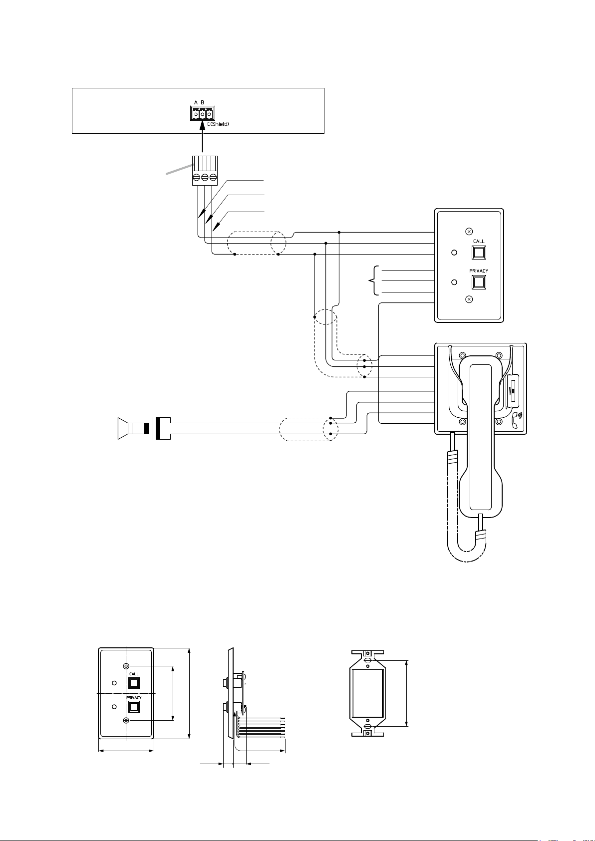
Substation interface unit
3P removable terminal plug
(supplied with the Substation
interface unit)
High-impedance speaker
(Impedance: 600 Ω or more)
Switch panel
(Figure shows the RS-140)
RS-141
N.C.
2-core shielded cable
2-core shielded cable
2-core shielded cable
Brown (A)
Red (B)
Orange (C)
Yellow (C+)
Green (B+)
Blue (A+)
Blue (COM)
Green (HOT)
Purple (H)
Brown (A)
Red (B)
Orange (C)
Yellow (C+)
Green (B+)
Blue (A+)
Purple (H)
Brown
Red
Orange
To the substation connection terminal
)]
3.2. Switch Panel and Option Handset Connections
Note
Cut out unused wires to avoid short-circuiting.
4. INSTALLATION
4.1. Switch Panel Installation
4.1.1. Dimensional diagram
[RS-140] [Mounting bracket (Supplied with the RS-140/143/144
Note:
70
The dimensions of RS-143 and RS-144 are the same as above.
115
68.5
12.3
200 or less
16.3
Unit: mm
83.5
Page 3

Note
When using the PA paging function, keep the switch panel as far away from the PA paging speaker as possible
to avoid acoustic feedback.
4.1.2. In-wall mounting using an electrical box
Mount the RS-140/143/144 to the YC-801 Flush-mount box mounted in the wall.
Accessory screws
The RS-140/143/144 comes with 2 types of screws to match
the box screw threads: M4 x 30 and UNC No. 6-32 x 30.
For the electrical box provided with unified threads, use the
UNC No. 6-32 x 30.
Machine screw M4 x 30
(supplied with the RS-140/143/144)
UNC No. 6-32 × 18
(supplied with the RS-140/143/144)
Switch panel
(Figure shows RS-140.)
4.1.3. On-wall mounting using a wall-mount box
Wall surface
83.5 mm
YC-801
Flush-mount box
Mounting bracket
(supplied with the RS-140/143/144)
Attach the RS-140/143/144 to the YC-802 Wall-mount box installed on a wall.
Accessory screws
The RS-140/143/144 comes with 2 types of screws to match the
box screw threads: M4 x 30 and UNC No. 6-32 x 30.
For the electrical box provided with unified threads, use the
UNC No. 6-32 x 30.
Machine screw M4 x 30
(supplied with the RS-140/143/144)
83.5 mm
UNC No. 6-32× 18
(supplied with the RS-140/143/144)
Mounting bracket
(supplied with the RS-140/143/144)
Wall surface
YC-802
Wall-mount box
Switch panel
(Figure shows RS-140.)
Page 4

4.2. Option Handset Installation
Mount the option handset to an electrical box mounted in the wall.
YC-302
2-gang electrical box
(option)
Machine screw M4 x 25
(supplied with the RS-141)
Wall surface
[Dimensional diagram]
116 71
46
83.5
115
48
Unit: mm
200 or less
220
Accessory screws
The RS-141 comes with 2 types of screws: M4 x 25 and UNC
RS-141
No. 6-32 x 18.
For the electrical box provided with unified threads, use the
UNC No. 6-32 x 18.
5. SPECIFICATIONS
Model Number RS -14 0 RS -14 3 RS -14 4
Call Button 1 Momentary (CALL) Momentary (EMERGENCY)
Call Button 2
Privacy Button Latching (PRIVACY)
Call Indicator Flashing red
Conversation Indicator Lit red
Privacy Indicator Lit red
Wiring 2-core shielded cable
Transmission Distance 0.5 km/ø0.5 mm (AWG24), 800 m/ø0.65 mm (AWG22),1300 m/ø0.9 mm (AWG19)
Operating Temperature 0 to +40°C
Finish Panel Stainless steel, hairline
Call Button 1 Resin, red
Call Button 2
Privacy Button Resin, white
Dimensions 70 (w) x 115 (h) x 28.6 (d) mm
Weight 80 g
Accessory Mounting bracket ... 1, No. 6-32 UNC x 18 ... 2, Machine screw M4 x 30 ... 2,
No. 6-32 UNC x 30 ... 2
Applicable Box Flush-mount box: YC-801 (option)
-
-
-
-
-
-
-
Wall-mount box: YC-802 (option)
Momentary (NORMAL)
Resin, white
Model Number RS -141
Handset Receiver Dynamic type
Handset Transmitter Electret condenser type
Wiring 2-core shielded cable
Handset Receiver
Volume Control
Operating Temperature 0 to +40°C
Finish ABS resin, pale white
Dimensions 116 (w) x 220 (h) x 71 (d) mm
Weight 350 g
Accessory No. 6-32 UNC x 18 ... 4, Machine screw M4 x 25 ... 4
Applicable Box 2-gang electrical box: YC-302 (option)
Note: The design and specications are subject to change without notice for improvement.
Manufacturer:
TOA Corporation
7-2-1, Minatojima-Nakamachi, Chuo-ku, Kobe, Hyogo, Japan
Slide Volume
Maximum control level: 12 – 18 dB
Traceability Information for Europe
Authorized representative:
TOA Electronics Europe GmbH
Suederstrasse 282, 20537 Hamburg, Germany
URL: http://www.toa.jp/
133-06-00029-00
 Loading...