

Page 1
Instruction/Installation Manual
Please follow the instructions in this manual to obtain the optimum results from this unit.
We also recommend that you keep this manual handy for future reference.
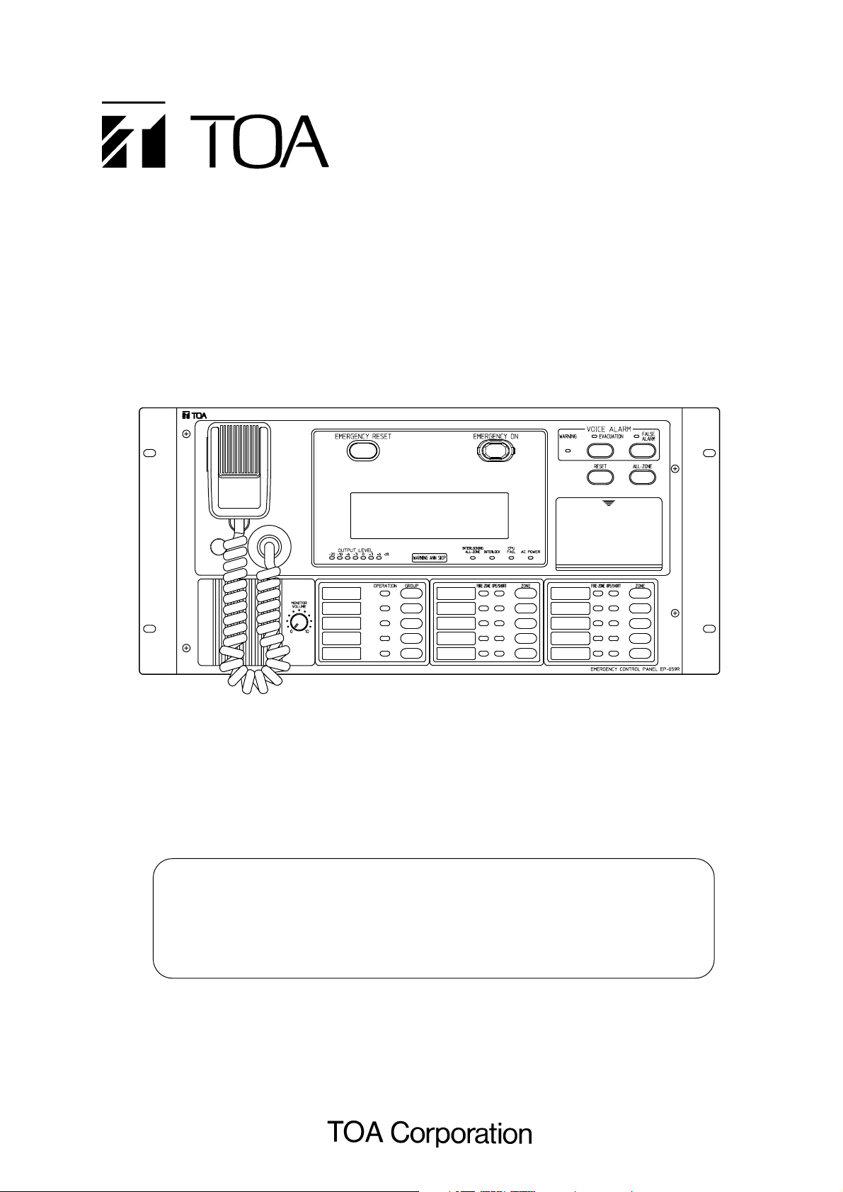
INTEGRATED REMOTE CONTROL UNIT
Model RM-971 Type
Note
The remote control unit operates in the same manner as the main rack in
emergency situations. Because the operation of the emergency PA system differs
depending on its type, confirm the remote control unit's emergency operations by
reading the instruction manual included with the main rack system.
Page 2

Page 3

3
1. SAFETY PRECAUTIONS .................................................................................................................. 5
2. HANDLING PRECAUTIONS ............................................................................................................. 6
3. EQUIPMENT CONFIGURATION ..................................................................................................... 6
4. NOMENCLATURE AND FUNCTIONS ........................................................................................... 7
5. DETAILS OF EMERGENCY BROADCAST OPERATIONS
5.1. Emergency Broadcast by Activation of the Fire Alarm System Fire Detector ...................................... 10
5.2. Emergency Broadcast by Emergency Telephone or Fire Button ......................................................... 12
5.3. Manually-Operated Emergency Broadcast .......................................................................................... 14
5.4. Voice Message Table ........................................................................................................................... 17
5.4.1. Voice alarm message ................................................................................................................. 17
5.4.2. Voice operation guide ................................................................................................................ 17
5.4.3. Emergency Control Panel EP-0510 screen display ................................................................... 18
6. HOW TO MAKE GENERAL BROADCAST
6.1. Announcements by Microphone ........................................................................................................... 19
6.2. Group Broadcast .................................................................................................................................. 20
6.3. About the Main Rack BGM Broadcast ................................................................................................. 21
6.3.1. Making the Main Rack BGM Broadcast ..................................................................................... 21
6.3.2. Making the Main Rack BGM Broadcast from the Integrated Remote Control Unit .................... 22
6.3.3. Equipment that can be make the Main Rack BGM Broadcast ................................................... 22
6.4. About the General-Purpose All-Zone Broadcast .................................................................................. 22
6.5. How to Use the Name Label ................................................................................................................ 23
7. DAILY INSPECTION
7.1. Automatic Inspection ............................................................................................................................ 24
7.1.1. CPU failure: CPU failed. ............................................................................................................. 24
7.1.2. Battery failure: Batteries of the main rack's DS-029B failed. ..................................................... 25
7.1.3. EP-029 failure: The remote control unit's Expansion Control Panel EP-029 failed. .................. 26
TABLE OF CONTENTS
Page 4

4
8. INSTALLATION
8.1. Notes on Panel Installation .................................................................................................................. 27
8.2. Chime Switch Installation ..................................................................................................................... 28
8.3. Inter-panel Connections (RM-971 type) ............................................................................................... 29
8.4. Connection of the Terminal Plate to the Main Rack (JP-0410) ............................................................ 30
8.4.1. Maximum line resistance ............................................................................................................ 30
8.4.2. Multiple remote control units connections .................................................................................. 30
8.4.3. Connection diagrams ................................................................................................................ 31
8.5. Remote Control Unit's DIP Switch Settings .......................................................................................... 32
8.5.1. EP-059R address setting ........................................................................................................... 32
8.5.2. Setting of the number of Expansion Control Panels EP-029 ..................................................... 33
8.5.3. Remote control mode setting ..................................................................................................... 33
8.5.4. Voice operation guide setting ..................................................................................................... 33
8.5.5. Shift switch setting ..................................................................................................................... 34
8.5.6. Shift switch (No.) setting: SW201 switches No. 1 through No. 4 ............................................... 36
Page 5
5
1. SAFETY PRECAUTIONS
• Be sure to read the instructions in this section carefully before use.
• Make sure to observe the instructions in this manual as the conventions of safety symbols and messages
regarded as very important precautions are included.
• We also recommend you keep this instruction manual handy for future reference.
Safety Symbol and Message Conventions
Safety symbols and messages described below are used in this manual to prevent bodily injury and property
damage which could result from mishandling. Before operating your product, read this manual first so you are
thoroughly aware of the potential safety hazards as well as understand the safety symbols and messages.
When Installing the Unit
• Do not expose the unit to rain or an environment
where it may be splashed by water or other liquids,
as doing so may result in fire or electric shock.
• Use the unit only with the voltage specified on the
unit. Using a voltage higher than that which is
specified may result in fire or electric shock.
• Do not cut, kink, otherwise damage nor modify the
power supply cord. In addition, avoid using the
power cord in close proximity to heaters, and
never place heavy objects -- including the unit
itself -- on the power cord, as doing so may result
in fire or electric shock.
When the Unit is in Use
• Should the following irregularity be found during
use, immediately switch off the AC breaker of the
main rack and contact your nearest TOA dealer.
Make no further attempt to operate the unit in this
condition as this may cause fire or electric shock.
· If you detect smoke or a strange smell coming
from the unit.
· If water or any metallic object gets into the unit
· If the unit falls, or the unit case breaks
· If the power supply cord is damaged (exposure
of the core, disconnection, etc.)
· If it is malfunctioning (no tone sounds.)
• To prevent a fire or electric shock, never open nor
remove the unit case as there are high voltage
components inside the unit. Refer all servicing to
your nearest TOA dealer.
• Do not place cups, bowls, or other containers of
liquid or metallic objects on top of the unit. If they
accidentally spill into the unit, this may cause a fire
or electric shock.
• Do not insert nor drop metallic objects or
flammable materials in the ventilation slots of the
unit's cover, as this may result in fire or electric
shock.
When Installing the Unit
• Do not block the upper panel ventilation slots in the
unit's cover. Doing so may cause heat to build up
inside the unit and result in fire.
• Avoid installing the unit in humid or dusty locations,
in locations exposed to the direct sunlight, near the
heaters, or in locations generating sooty smoke or
steam as doing otherwise may result in fire or
electric shock.
Indicates a potentially hazardous situation which, if mishandled,
could result in death or serious personal injury.
Indicates a potentially hazardous situation which, if mishandled,
could result in moderate or minor personal injury, and/or property
damage.
WARNING
CAUTION
CAUTION
WARNING
Page 6
6
2. HANDLING PRECAUTIONS
• Leave the installation to the shop from where the system was purchased. Also contact the shop when
moving the system from one place to another or mounting additional components in the rack.
• To clean, wipe with a dry, soft cloth. Do not use benzine, thinner or chemically-processed towel because the
unit may be deformed or its finish discolored.
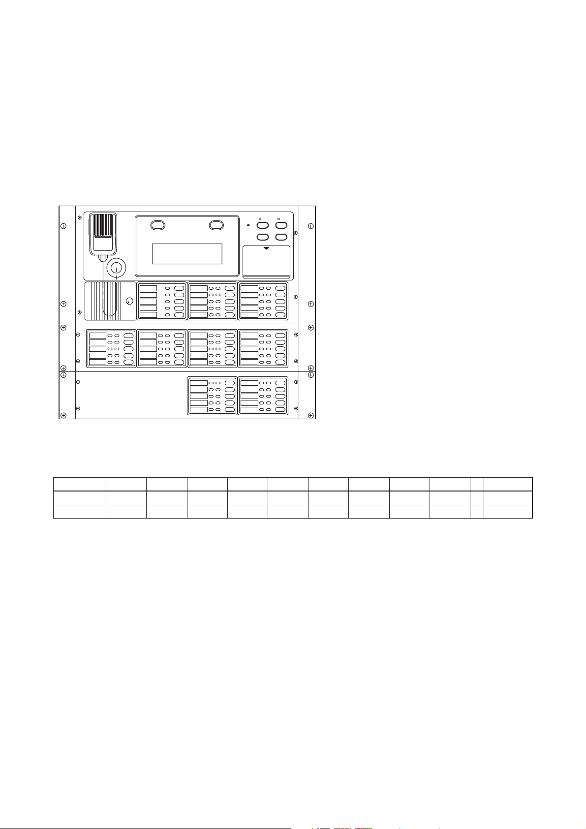
3.EQUIPMENT CONFIGURATION
(The figure shows Model RM971-40.)
Integrated Remote Control Panel
EP-059R
20-zone Expansion Control Panel
EP-029-20
10-zone Expansion Control Panel
EP-029-10
Note: The number of EP-029 units to be connected differs depending on the number of zones.
10 zones 20 zones 30 zones 40 zones 50 zones 60 zones 70 zones 80 zones 90 zones
...
330 zones
EP-029-10 010101010 0
EP-029-20 001122334 16
Page 7
7
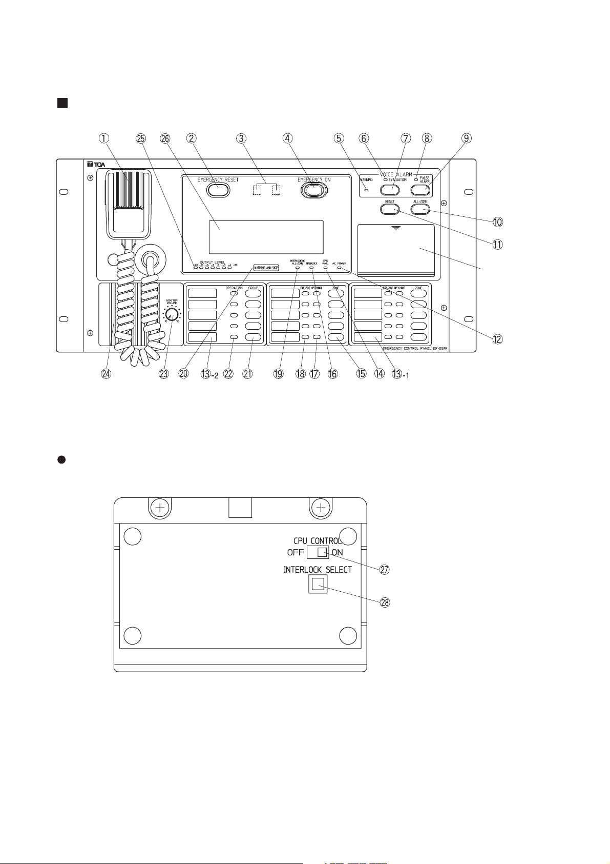
4. NOMENCLATURE AND FUNCTIONS
Integrated Remote Control Panel EP-059R
EP-059R's CPU control section
CPU control operation
sections (Refer to the
figure below.)
CPU control on-off switch
Interlock mode key
Page 8

8
PA microphone
Make announcements while holding down the
microphone talk switch. Announcements from this
microphone take precedence over any other
broadcasts in emergency situations.
Emergency reset key
When the emergency situation is finished, press
this key after resetting the fire detector,
emergency telephone or fire button.
Fire indicator
Automatically lights when the emergency PA
system is activated by the automatic fire alarm
system's fire detector, emergency telephone or
fire button. This indicator also lights when the
Emergency key is pressed. It remains lit during
Warning Announcement, Evacuation
Announcement or False Alarm Announcement,
and is extinguished when the Emergency reset
key is pressed after resetting the fire detector,
emergency telephone or fire button.
Emergency key
Press this key when making emergency
broadcast manually or when switching the
broadcast from Warning Announcement to
Evacuation Announcement. Break the protection
cover to use this key.
Warning Announcement indicator
Flashes before and after Warning Announcement,
and remains lit during Warning Announcement.
Evacuation Announcement indicator
Remains lit during Evacuation Announcement and
flashes while the second signal tone is sounding.
Evacuation Announcement key
Press this key to make Evacuation
Announcement after confirming there is a fire.
False Alarm Announcement indicator
Remains lit during False Alarm Announcement
and flashes after False Alarm Announcement
completion.
False Alarm Announcement key
Press this key to make False Alarm
Announcement after confirming the false alarm.
All-zone broadcast key
Press this key when simultaneously making
emergency or general-purpose broadcast to the
entire zone.
Broadcast reset key
Press this key to reset emergency or generalpurpose broadcast.
AC power indicator
Lights when the system is operating on AC.
Name label
(1) Write the name of each broadcast zone
selector key.
(2) Write the name of each broadcast group
selector key.
CPU failure indicator
Lights or flashes when a computer circuitry fails.
Zone selector key
Press this key to make emergency or generalpurpose announcements to individual floors or
zones. Press this key again to reset generalpurpose announcements.
Fire alarm interlock mode indicator
Lights when the fire alarm interlock mode is set.
Zone/short circuit indicator
Lights green to indicate broadcast is being made
to the corresponding floor. Lights red to indicate
the speaker lines on the corresponding floor are
shorted. Because the shorted speaker lines are
automatically disconnected, broadcast cannot be
made to that floor.
Fire floor indicator
Lights to indicate the fire floor when the PA
system receives a fire signal from the fire alarm
system.
Fire alarm all-zone interlock mode indicator
Lights when the fire alarm all-zone interlock mode
is set.
Warning Announcement Non-interlock
indicator
Lights when Warning Announcement Noninterlock mode is set. Fire detector-activated
Warning Announcement is disabled when in noninterlock mode.
A fire signal tone is sounded from the remote
control unit's control section when the unit is
activated by the fire detector. In such cases,
investigate the cause immediately and make
appropriate announcements.
Group selector key
Press this key to make general-purpose
broadcast to the designated zone groups. Press
this key again to reset.
Group indicator
Lights when general-purpose broadcast is made
to the corresponding zone group.
22
21
20
19
181716
15
141312
11
10
987
654
3
2
1
Page 9

9
Monitor volume control
Adjusts the monitor speaker volume. The volume
increases as the volume control is rotated
clockwise.
Note: Emergency announcements are made at
the fixed volume level regardless of the monitor
volume control setting. Therefore, the volume of
the emergency broadcast cannot be adjusted.
Monitor speaker
Monitors each broadcast and provides voice
operation guides for emergency broadcast as well
as warning tones for system malfunctions. While
the PA microphone is in use, the monitor speaker
is disabled to prevent feedback.
Output level meter
Indicates a signal output level. See to it that the
meter indicator stays within the green area during
system operation.
Liquid Crystal Display
Displays emergency broadcast operation guides,
general-purpose broadcasting status, and system
malfunctions.
CPU control on/off switch
Normally, set this switch to the ON position. When
the CPU fails and cannot be controlled, setting
the control switch to the OFF position permits only
the all-zone broadcast to be made from the PA
microphone.
Interlock mode key
Selects either "fire alarm interlock" or "fire alarm
all-zone interlock" mode. Each depression of this
key causes both modes to alternate.
Memo
Warning Announcement is always made
automatically by being activated by a fire detector.
2827262524
23
Page 10
10
•
Broadcast remains silent
after microphone
announcement completion.
•
Check the site and manually
broadcast Evacuation
Announcement or False
Alarm Announcement or
give evacuation instructions
using the PA microphone.
5. DETAILS OF EMERGENCY BROADCAST OPERATIONS
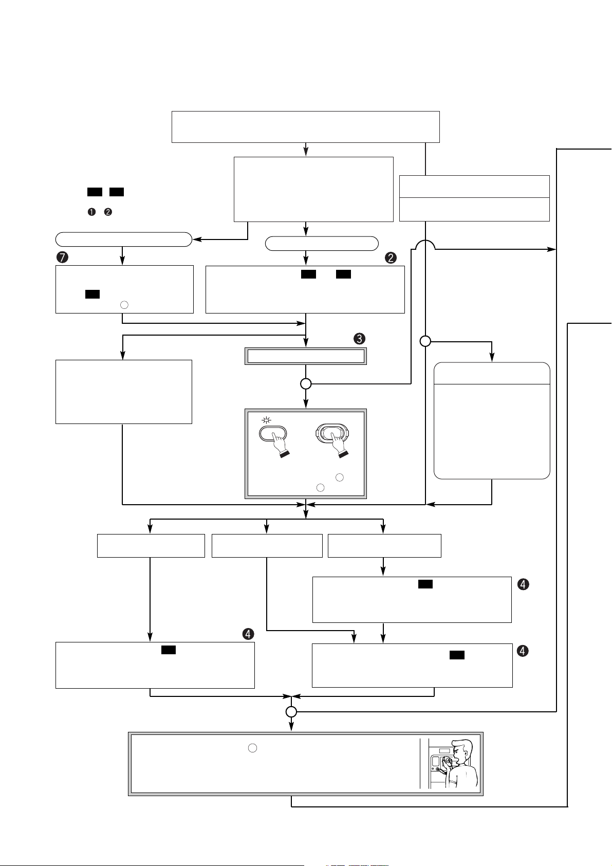
5.1. Emergency Broadcast by Activation of the Fire Alarm System Fire Detector
Activation of the Fire Alarm System's Fire Detector
(Current general-purpose broadcast stops.)
• Fire indicator lights.
• Fire floor indicator lights.
• Zone indicators of the fire floor and
interlock floor light. (Interlock mode)
• Zone indicators of all floors light. (Allzone interlock mode)
Evacuation Announcement Interval
timer is activated.
*3
Evacuation Announcement Interval
time setting XX minute XX second
Warning Interlock mode
Warning Non-interlock mode
Visit and check the site.
Press the Evacuation
Announcement key or
Emergency key .
4
7
Announcement using
the PA microphone
Activation of one of the following
*1
• Emergency telephone
• Fire button
• Other detector
• Fire confirmation signal from the
fire alarm system
All-zone Evacuation Announcement ( )
*2,*4
Broadcasting floor: All floors
Information on the floor first alarm activating is included.
M2
Evacuation Announcement ( )
*2
Broadcasting floor: Fire floor and interlock floor
(Interlock mode) or all floors (All-zone interlock mode)
Information on the floor first alarm activating is included.
M2
• Using the PA microphone , make appropriate announcements for
evacuation. After the microphone announcement is completed, only the
"Second signal" warning tone is repeated.
• Select other floors as well as required.
*4
1
Warning Announcement is not made.
A fire signal tone and voice operation
guide ( ) are provided from the
monitor speaker .
24
M6
• Key numbers are those shown in "4.
NOMENCLATURE AND FUNCTIONS" on
p. 7.
• Marks
,
....in this section represent
voice alarms or voice operation guides. (p. 17)
• Marks
,
....represent the indications to
be displayed on the screen. (p. 18)
M2M1
Fire
False Alarm Announcement
Time is up.
Time is up.
All-zone Broadcast
Interval timer [Off]
All-zone Broadcast
Interval timer [0 minute]
Time setting for All-zone
Broadcast Interval timer
All-zone Broadcast Timer starts.
Time is up.
Evacuation Announcement ( )
*2
Broadcasting floor: Fire floor and interlock floor
(Interlock mode) or all floors (All-zone interlock mode)
Information on the floor first alarm activating is included.
M2
Fire
False Alarm Announcement
Warning Announcement ( and )
Broadcasting floor: Fire floor and interlock floor
(Interlock mode) or all floors (All-zone interlock mode)
Information on the alarm activating floor is included.
M5M1
EVACUATION
EMERGENCY ON
Page 11
11
*1
When fire detectors on different floors simultaneously operate or when the detector on other floor operates
during Warning Announcement, Evacuation Announcement is provided upon completion of the Warning
Announcement.
*2
Even when another fire detector operates after Warning Announcement is made, Evacuation
Announcement informs the first-operated detector's floor as the fire floor.
*3
During the operation of Evacuation Announcement Interval Timer, even when the Broadcast reset key is
pressed and broadcast is reset, the Evacuation timer continues to operate without stopping.
*4
After All-zone Broadcast Interval Timer's set time is up, only all-zone broadcast can be made. Broadcasting
floors cannot be changed, nor can broadcast be reset.
11
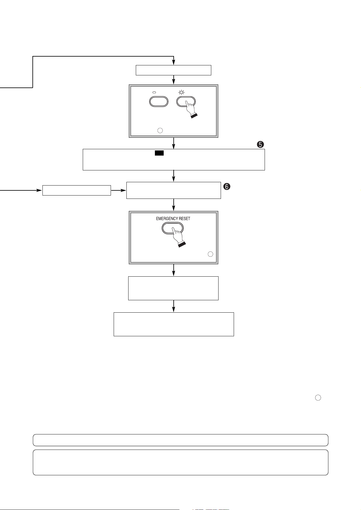
False Alarm Announcement
Press the False Alarm Announcement key .
9
False Alarm Announcement ( )
Broadcasting floor: Floors to which Warning Announcement or Evacuation
Announcement was made
M6
Reset the fire detector, emergency
telephone or fire button.
Extinguishment of a fire
Press the Emergency reset key .
2
• Fire indicator is extinguished.
• Fire floor indicator is extinguished.
• Zone indicator is extinguished.
Restoration
Broadcast mode the system was last in before
Warning Announcement was made is restored.
If the Emergency reset key is pressed
without resetting the fire detector,
emergency telephone or fire button, the
system interprets the key depression as fire
status and initiates broadcast.
When a false alarm or the extinguishment
of a fire is confirmed, be sure to reset the
fire detector, emergency telephone or fire
button before pressing the Emergency reset
key.
The PA microphone can be used at any time because it is given the highest priority.
If the CPU failure indicator lights or flashes during the operation of the system, open the door and set the
computer control on-off switch to the OFF position. This permits attenuator-free all-zone broadcast to be
made using the PA microphone. (See p. 24.)
EVACUATION
FALSE
ALARM
Page 12

12
5.2. Emergency Broadcast by Emergency Telephone or Fire Button
*1
Even when another emergency telephone or fire button operates after Warning Announcement is made,
Evacuation Announcement informs the first-operated device's floor as the fire floor.
*2
After All-zone Broadcast Interval Timer's set time is up, only all-zone broadcast can be made. Broadcasting
floors cannot be changed, nor can broadcast be reset.
Activation from the emergency telephone or fire button
(Current general-purpose broadcast stops.)
•
Fire indicator lights.
•
Fire floor indicator lights.
•
Zone indicators of the fire floor and interlock
floor light. (Interlock mode)
•
Zone indicators of all floors light. (All-zone
interlock mode)
Warning Mode Evacuation mode
Warning Announcement ( and )
Broadcasting floor: Fire floor and interlock floor (Interlock
mode) or all floors (All-zone interlock mode)
Information on the floor first alarm activating is included.
M5M1
All-zone Broadcast
Interval timer [Off]
All-zone Broadcast
Interval timer [0 minute]
Time setting for All-zone
Broadcast Interval timer
All-zone Broadcast Timer starts.
Evacuation Announcement ( )
*1
Broadcasting floor: Fire floor and interlock floor
(Interlock mode) or all floors (All-zone interlock mode)
Information on the floor first alarm activating is included.
M2
All-zone Evacuation Announcement ( )
*1,*2
Broadcasting floor: All floors
Information on the floor first alarm activating is included.
M2
Time is up.
Evacuation Announcement ( )
*1
Broadcasting floor: Fire floor and interlock floor
(Interlock mode) or all floors (All-zone interlock mode)
Information on the floor first alarm activating is included.
M2
•
Using the PA microphone , make appropriate announcements
for evacuation. After the microphone announcement is completed,
only the "Second signal" warning tone is repeated.
•
Select other floors as well as required.
*2
1
Fire
False Alarm Announcement
• Key numbers are those shown in "4.
NOMENCLATURE AND FUNCTIONS" on
p. 7.
• Marks
,
....in this section represent
voice alarms or voice operation guides. (p. 17)
• Marks
,
....represent the indications to
be displayed on the screen. (p. 18)
M2M1
Page 13

13
False Alarm Announcement
Press the False Alarm Announcement key .
9
False Alarm Announcement ( )
Broadcasting floor: Floors to which Warning Announcement or Evacuation
Announcement was made
M3
Reset the fire detector, emergency
telephone or fire button.
Extinguishment of a fire
Press the Emergency reset key .
2
• Fire indicator is extinguished.
• Fire floor indicator is extinguished.
• Zone indicator is extinguished.
Restoration
Broadcast mode the system was last in before
Warning Announcement was made is restored.
If the Emergency reset key is pressed
without resetting the fire detector,
emergency telephone or fire button, the
system interprets the key depression as
fire status and initiates broadcast.
When a false alarm or the extinguishment
of a fire is confirmed, be sure to reset the
fire detector, emergency telephone or fire
button before pressing the Emergency
reset key.
The PA microphone can be used at any time because it is given the highest priority.
If the CPU failure indicator lights or flashes during the operation of the system, open the door and set the
computer control on-off switch to the OFF position. This permits attenuator-free all-zone broadcast to be
made using the PA microphone. (See p. 24.)
EVACUATION
FALSE
ALARM
Page 14

14
Evacuation Announcement ( )
Broadcasting floor: Activated floor (Fire floor) interlock
floor and selected floors (Interlock mode) or all floors
(All-zone interlock mode)
Information on the floor first alarm activating is included.
M2
All-zone Evacuation Announcement ( )
*5
Broadcasting floor: All floors
Information on the floor first alarm activating is included.
M2
5.3. Manually-Operated Emergency Broadcast
• Key numbers are those shown in "6. NOMENCLATURE AND FUNCTIONS" on p. 7.
• Marks , ....in this section represent voice alarms or voice operation guides. (p. 17)
• Marks , ....represent the indications to be displayed on the screen. (p. 18)
M2M1
Activation of one of the following
*1
• Emergency telephone
• Fire button
• Fire detector
Evacuation Announcement Interval
timer is activated.
*4
Evacuation Announcement Interval
time setting XX minute XX second
• Broadcast remains silent
after microphone
announcement completion.
• Check the site and manually
broadcast Evacuation
Announcement or False
Alarm Announcement or
give evacuation instructions
using the PA microphone.
Announcement using
the PA microphone
Time is up.
Time is up.
All-zone Broadcast
Interval timer [Off]
All-zone Broadcast
Interval timer [0 minute]
Time setting for All-zone
Broadcast Interval timer
All-zone Broadcast Timer starts.
Evacuation Announcement ( )
Broadcasting floor: Activated floor (Fire floor) interlock
floor and selected floors (Interlock mode) or all floors
(All-zone interlock mode)
Information on the floor first alarm activating is included.
M2
Time is up.
Page 15

15
False Alarm Announcement
Manual operation: When fire information is received
Press the Emergency key .
(Current general-purpose broadcast stops.)
4
Press the desired zone selector key or
All-zone broadcast key .
10
15
B
To page 16
B
To page 16
A
To page 16
Warning Mode Evacuation mode
All-zone Broadcast
Interval timer [Off]
All-zone Broadcast
Interval timer [0 minute]
Time setting for All-zone
Broadcast Interval timer
All-zone Broadcast Timer starts.
Time is up.
Fire
False Alarm Announcement
•
Using the PA microphone , make appropriate announcements for
evacuation. After the microphone announcement is completed, only
the "Second signal" warning tone is repeated.
•
Select other floors as well as required.
*5
1
Warning Announcement ( and )
Broadcasting floor: Selected floors
*2
Floor information is not included.
M5M1
Fire
Visit and check the site.
Press the Evacuation
Announcement key or
Emergency key .
4
7
Evacuation Announcement ( )
*3
Broadcasting floor: Selected floors
Floor information is not included.
M2
Evacuation Announcement ( )
*3
Broadcasting floor: Selected floors
Floor information is not included.
M2
All-zone Evacuation Announcement ( )
*3, *5
Broadcasting floor: Selected floors
Floor information is not included.
M2
EMERGENCY ON
EVACUATION
EMERGENCY ON
Page 16

16
False Alarm Announcement
Press the False Alarm Announcement key .
9
False Alarm Announcement ( )
Broadcasting floor: Floors to which Warning Announcement or Evacuation
Announcement was made
M3
Reset the fire detector, emergency
telephone or fire button.
Extinguishment of a fire
Press the Emergency reset key .
2
• Fire indicator is extinguished.
• Fire floor indicator is extinguished.
• Zone indicator is extinguished.
Restoration
Broadcast mode the system was last in before
Warning Announcement was made is restored.
If the Emergency reset key is pressed
without resetting the fire detector,
emergency telephone or fire button, the
system interprets the key depression as
fire status and initiates broadcast.
When a false alarm or the extinguishment
of a fire is confirmed, be sure to reset the
fire detector, emergency telephone or fire
button before pressing the Emergency
reset key.
B
Continued from previous page
A
Continued from previous page
*1
If one of these devices is operated in the middle of Warning Announcement, Evacuation Announcement is
made after the Warning Announcement message is completed.
*2
When the broadcasting floor is selected manually, announcements are not broadcast to the floor next
above the selected floor.
*3
When a fire detector, emergency telephone or fire button operates after manually-operated Warning
Announcement is completed, subsequent Evacuation Announcement contains floor information.
*4
During the operation of Evacuation Announcement Interval Timer, even when the Broadcast reset key is
pressed and broadcast is reset, the Evacuation timer continues to operate without stopping.
*5
After All-zone Broadcast Interval Timer's set time is up, only all-zone broadcast can be made. Broadcasting
floors cannot be changed, nor can broadcast be reset.
11
The PA microphone can be used at any time because it is given the highest priority.
If the CPU failure indicator lights or flashes during the operation of the system, open the door and set the
computer control on-off switch to the OFF position. This permits attenuator-free all-zone broadcast to be
made using the PA microphone. (See p. 24.)
EVACUATION
FALSE
ALARM
Page 17

17
The microphone is given the highest priority and can be used at any time of these procedures. The
following message is displayed during the microphone announcement.
Warning Announcement Repeats twice a combined broadcast of the first signal +
announcement by female voice, "Attention please. The fire alarm
system (on the [nth] floor) is indicating a fire. We're investigating the
cause. Please wait for further information."
Evacuation Announcement Continuously repeats a combined broadcast of the first signal +
announcement by male voice, " There is a fire [on the [nth] floor].
Please evacuate as quickly as possibie." + first signal + same
announcement + second signal. If an announcement is made using
the PA microphone during the Evacuation Announcement, only a
second signal tone is repeatedly sounded after microphone
announcement completion.
False Alarm Announcement Repeats twice a combined broadcast of the first signal +
announcement by female voice, "Attention please. A few minutes ago
we announced there may be a fire. However, there is no fire. Once
again, there is no fire."
M3
M2
M1
Press the broadcast floor selector.
Transmitted a warning announcement. Visit and check the site. Press the evacuation
announcement key when there is a fire. If there is no fire, press the false alarm key.
Received a fire signal. Visit and check the site. Press the evacuation announcement key when there
is a fire. If there is no fire, stop the automatic fire alarm system, then press the emergency reset
key.
M6
M5
M4
5.4. Voice Message Table
5.4.1. Voice alarm message
The following messages are provided from the speakers on the broadcasting floor.
Floor information in Warning/Evacuation Announcement
(1) Manually-operated emergency announcements contain no fire floor information.
(2)Even when another fire detector operates after Warning Announcement is made, the first-operated
detector's floor is used in Evacuation Announcement.
5.4.2. Voice operation guide
The following messages are provided only from the monitor speaker on the front operation section.
Represents one of the three voice alarm messages, Warning, Evacuation or False Alarm.
Page 18

18
5.4.3. Emergency Control Panel EP-0510 screen display
Page 19

19
6. HOW TO MAKE GENERAL BROADCAST
6.1. Announcements by Microphone
1. Select the desired broadcast zone.
• Press the [All-zone Broadcast] key to make broadcast simultaneously to the entire area.
• Press the [Group] selector key to make group broadcast.
• Press the [Zone] selector key to make broadcast to individual zones.
321
Note
When the power switch on the main rack's pre-amplifier panel is set to the OFF position, the speaker line is
connected about one second after the power is switched on to prevent noise generated when the power is
switched on.
2. Press the microphone talk switch. When the chime switch
is installed, sounding a chime before and after
announcement using the switch makes the announcement
more effective.
3. Press the [Reset] key to reset the broadcast zone. To
reset group or individual zone broadcast, press the
corresponding key again.
4
5
Page 20

20
6.2. Group Broadcast
This function allows the same broadcast to be simultaneously sent to different zones by grouping them
together. For example, if the first and second floors are assigned to Group selector key No. 1, announcements
can be simultaneously made to both floors by simply pressing the key No. 1. Refer to the "Installation Manual Writing" enclosed with the EP-0510 (main rack) for group assignment.
The following types of group broadcast are made available.
1. Main Rack Group Broadcast
Use the main rack's key to make this broadcast. There are five group selector keys. If more are needed, the
individual zone keys can be converted into the group selector keys.
Operations
• To make group broadcast, press the Group selector key.
• To terminate group broadcast, press either the same key again or Broadcast reset key.
• To simultaneously make the same broadcast to two groups, press the two corresponding Group selector
keys.
• To include additional floors in the group broadcast, press the Group selector key, and then the desired zone
selector keys.
2. Main Rack Attenuator-Free Group Broadcast
To make this broadcast, use the main rack's group selector keys assigned to the attenuator-free broadcast
groups. If the key is pressed, its group indicator lights and the indication "Attenuator-free broadcast" is
displayed on the screen. The attenuator-free broadcast is allowed to go through at the maximum volume level
regardless of the attenuator setting, and is used for urgent communication. Operations are the same as those
described in Item 1 above.
3. Integrated Remote Control Unit Group Broadcast
This broadcast is made from the Integrated Remote Control Unit. The Integrated Remote Control Unit's group
broadcast keys correspond with those of the main rack. Operations are also the same.
4. Integrated Remote Control Unit Attenuator-Free Group Broadcast
This attenuator-free broadcast is made from the Integrated Remote Control Unit. The Integrated Remote
Control Unit's group broadcast keys correspond with those of the main rack. Operations are also the same.
5. General-Purpose Remote Control Unit Group Broadcast
This broadcast is made from the General-Purpose Remote Control Unit. Different groups from those of the
main rack can be set. For operations, refer to the instruction manual included with the General-Purpose
Remote Control Unit.
6. General-Purpose Remote Control Unit Attenuator-Free Group Broadcast
This broadcast is made from the General-Purpose Remote Control Unit. Different groups from those of the
main rack can be set.
7. Program Timer-Activated (Attenuator-Free) Group Broadcast
By activating the Melody Chime by Program Timer, a chime tone can be sounded in the specified zones. This
chime play can also be set for attenuator-free group broadcast.
8. Digital Announcer (Attenuator-Free) Group Broadcast
By activating the Digital Announcer by timer, recorded announcements can be broadcast to the specified
zones. The Digital Announcer can also be set for attenuator-free group broadcast.
Page 21

21
6.3. About the Main Rack BGM Broadcast
The main rack system comes with the Main Rack BGM Broadcast function, which permits BGM to be
broadcast from source equipment having no busy control output terminal. Set the purpose of use of the group
or zone selector keys for [BGM] at the EP-0510 Integrated Control Panel. The Main Rack BGM Broadcast can
be made by pressing the group or zone selector keys set for [BGM] at both the EP-0510 and Integrated
Remote Control Unit. For settings, refer to the "Installation Manual - Writing".
6.3.1. Making the Main Rack BGM Broadcast
1. Press the main rack's group or zone selector key set for BGM.
2. The corresponding zone indicator lights.
3. The message [General BGM] appears on the EP-0510's display.
4. BGM can be broadcast now from the BGM source equipment.
Notes
• Priority level of the Main Rack BGM can be set by data writing at the EP-0510. Refer to the "Installation
Manual - Writing" enclosed with the EP-0510.
• When current broadcast is given higher priority over the Main Rack BGM, BGM cannot be broadcast even
though the group or zone selector key set for BGM is pressed.
Selected key
Page 22

22
5. To terminate the Main Rack BGM Broadcast, press the selected key again. The corresponding zone
indicator is extinguished, and the message on the screen also disappears.
Note
• Even if the Broadcast Reset key is pressed during the Main Rack BGM Broadcast, the BGM is continuously
broadcast without being interrupted.
• The Main Rack BGM broadcast function may be disabled depending on the main rack the remote control
unit is connected to. For details, refer to the instruction manual enclosed with the Main Rack EP-0510.
6.3.2. Making the Main Rack BGM Broadcast from the Integrated Remote Control Unit
The Main Rack BGM Broadcast can be made from the Integrated Remote Control Unit as well. To broadcast,
simply press the group or zone selector key set for [BGM] by data writing at the EP-0510 Integrated Control
Panel. Other operations also remain the same as those described in the above section "Making the Main Rack
BGM Broadcast".
Note
The Main Rack BGM broadcast function may be disabled depending on the main rack the remote control unit
is connected to. For details, refer to the instruction manual enclosed with the Main Rack EP-0510.
6.3.3. Equipment that can make the Main Rack BGM Broadcast
Using the EP-0510's internal switch, either the main rack or Integrated Remote Control Unit can be designate
as equipment that can make the Main Rack BGM Broadcast. The system is set by the factory to enable the
broadcast from both units. For the setting contents and method, refer to the section "SETTING OF THE
INTEGRATED CONTROL PANEL EP-0510" in the "Installation Manual - Basic Installation" enclosed with the
EP-0510.
Note
• When unit is not registered as Main Rack BGM Broadcasting Equipment, the group or zone selector key
cannot be used even if it is set for [BGM].
• The Main Rack BGM broadcast function may be disabled depending on the main rack the remote control
unit is connected to. For details, refer to the instruction manual enclosed with the Main Rack EP-0510.
6.4. About the General-Purpose All-Zone Broadcast
Initial status of the general-purpose all-zone broadcast is set for "normal all-zone broadcast" by the factory. If
the "attenuator-free general-purpose all-zone broadcast" is more desirable, which allows announcements to
go through regardless of the speaker attenuator setting, the setting can be changed by data writing. Refer to
the "Installation Manual - Writing" enclosed with the EP-0510 (main rack) for details.
Extinguishes.
Selected key
Page 23

23
6.5. How to Use the Name Label
Write the names of the zone or group selector keys in the name label.
Removing the label cover
Insert screwdriver blade into an opening (marked with an arrow in the figure) to remove the cover, then take
out the label. After writing, replace the label and cover.
1
2
Name label
Cover
Page 24

24
7. DAILY INSPECTION
7.1. Automatic Inspection
The Integrated Remote Control Unit is provided with an automatic inspection function by computer, which
automatically inspects batteries every 24 hours, and other items on a round-the-clock basis. Detected
irregularities are displayed on the Integrated Remote Control Panel EP-059R's screen. Shown below are the
indications displayed when irregularities are detected, and the countermeasures.
7.1.1. CPU failure: CPU failed.
[Failure indication and countermeasures]
Should the failure indicator light or flash again,
contact the shop from where the unit was
purchased, or TOA's service agent immediately.
Leave the CPU control switch OFF temporarily.
In this state, only all-zone broadcast by PA
microphone is enabled.
Press to talk.
CPU failure indicator
lights red or flashes.
CPU control switch
Shift the CPU control switch to the OFF position, and then back to the ON position again.
Page 25

25
7.1.2. Battery failure: Batteries of the main rack's DS-029B failed.
The main rack's batteries are automatically inspected every 24 hours. Should a failure be detected during a
manual inspection, it is alerted in forms of display and warning tone as well.
[Failure indication and measures]
Warning beep
(Not sounded during emergency broadcast.)
Display
CPU control switch
Shift the CPU control switch to the OFF position, and then back to the ON position.
Broadcast reset key
Warning tone stops, and the failure indication disappears.
Selected general-purpose broadcast speaker lines are disconnected.
Manually check the main rack's Emergency
Power Supply Panel DS-029B. Refer to the
instruction manual included with the main rack.
Should the failure indication be displayed again,
contact the shop from where the unit was
purchased, or TOA's service agent immediately.
(Press the [Broadcast Reset] key to stop a
warning tone.)
Check the date of installation of the main rack
batteries. If four years have passed since the
installation, contact the shop from where the
unit was purchased, or TOA's service agent
immediately because the batteries must be
replaced with new ones.
Page 26

26
7.1.3. EP-029 failure: The remote control unit's Expansion Control Panel EP-029 failed.
[Failure indication and measures]
Warning beep
(Not sounded during emergency broadcast.)
Display
Defective EP-029's address (0-F) is displayed.
CPU control switch
Shift the CPU control switch to the OFF position, and then back to the ON position.
Broadcast reset key
Warning tone stops, and the failure indication disappears.
Selected general-purpose broadcast speaker lines are disconnected.
Should the failure indicator light or flash again,
contact the shop from where the unit was
purchased, or TOA's service agent immediately.
(To stop a warning tone, press the [Broadcast
Reset] key.)
Leave the CPU control switch OFF temporarily.
In this state, only all-zone broadcast by PA
microphone is enabled.
Press to talk.
Page 27

27
8. INSTALLATION
8.1. Notes on Panel Installation
• Install the control panel (EP-059R and EP-029) so that all of its keys may be positioned at a height of 0.8 - 1.5 m from the floor.
• When mounting individual panels in the remote control unit wall mounting cabinet (CR-092R, etc.), mount the terminal block assembly to the cabinet.
When installing individual panels in equipment rack or case other than the wall mounting cabinet, install the terminal block assembly in the designated
position on the EP-059R's rear panel.
The figure shows the RM-971-330.
Under 1,500 mm
179 mm89 mm89 mm89 mm89 mm
Over 800 mm
Floor surface
Installation position of terminal block assembly
(supplied with EP-059R)
Installation position of terminal block assembly
(supplied with EP-059R)
(EP-059R's rear panel)
(Wall mounting cabinet)
Page 28

28
8.2. Chime Switch Installation
Follow the procedures below to install the supplied chime switch used to activate the main rack's chime device
from the remote control unit.
1. Break a chime switch knockout hole in the
control panel.
2. Open the panel by removing two screws on
the right of the control panel.
3. Install the chime switch using the supplied
screws (3x6).
4. Connect the chime switch connector to
CN213 on the control circuit board.
5. Close the panel, and attach the supplied
label.
Chime switch
Screw (3x6)
Mount from the back of the panel.
SW201
SW202
CN213
(2P)
Control circuit board
Chime
Supplied label
Chime
Page 29

EP-059R's terminal plate
To main rack
Main rack
Jumper wire
EP-059R's terminal plate
29
8.3. Inter-panel Connections (RM-971 type)
Note: When the length of control connector cable and power
connector cable is insufficient, use the optional Cable Set
YR-932.
YR-932's cable composition
1. EP-EP Control Connector Cable (5 m) x 1
2. EP-EP Power Connector Cable (5 m) x 1
Page 30

30
8.4. Connection of the Terminal Plate to the Main Rack (JP-0410)
Use shielded, heat-resistant, twisted paired cable for connection.
Connect the JP-0410's front-mounted terminal block and remote control unit's terminal plate.
The maximum cable length between main rack and remote control unit is 800 m. However, the distance may
be shorter than 800 m depending on the type and zone numbers of remote control units.
8.4.1. Maximum line resistance
Zone numbers Power cable (1 pair) Control cable (4 pairs)
10 Under 5 Ω Under 50 Ω
20 Under 3 Ω Under 50 Ω
30 Under 2.5 Ω Under 50 Ω
40 Under 1.5 Ω Under 50 Ω
50 -90 Under 1 Ω Under 50 Ω
Over 100 Under 0.5 Ω Under 50 Ω
8.4.2. Multiple remote control units connections
• Be sure to branch individual cables at the main rack when connecting multiple remote control units.
• Up to eight remote control units can be connected. Because the power is supplied from the main rack, the
Expansion DC Power Supply Panel or Emergency Power Supply Panel may have to be additionally
mounted in the main rack. For details, refer to the sections "Emergency Power Supply Panel DS-029B
Connection" and "DC Power Supply Panel Connection" in the Installation Manual - Basic Installation for the
FS-970 Series.
Remote control unit
Main Rack
Main Rack
Remote control unit Remote control unit Remote control unit
Remote control unit
Remote control unit
Page 31

31
8.4.3. Connection diagrams
Use shielded, heat-resistant, twisted paired cable for connection.
Terminal plate of the first remote control unit (address 0)
and fifth unit (address 4).
Terminal plate of the third remote control unit (address 2)
and seventh unit (address 6).
Terminal plate of the second remote control unit (address 1)
and sixth unit (address 5).
Terminal plate of the fourth remote control unit (address 3)
and eighth unit (address 7).
JP-0410's front-mounted terminal block (upper row)
Page 32

32
8.5. Remote Control Unit's DIP Switch Settings
Open the door of the Integrated Control Panel EP059R by removing its two screws shown in the figure
on the right.
• Set DIP switches SW201 and SW202 on the internal
circuit board.
SW201
No. Setting Function
1-4 EP-029 shift switch
5 Always OFF
6-8 EP-059R address
SW202
No. Setting Function
1 Remote control mode
2 Voice operation guide
3 EP-029 shift switch
4-8 EP-029 unit numbers
8.5.1. EP-059R address setting
Use SW201's switches No. 6 - No. 8 to set the remote control unit's address. When only one remote control
unit is connected, set its address for "0". The EP-059R's address is set for "0" at the factory.
12345678
ON
OFF
SW201
SW201
SW202
12345678
ON
OFF
SW202
678
ON
First unit Address 0
OFF
Fifth unit Address 4
ON
OFF
678
678
ON
Second unit Address 1
OFF
678
ON
Third unit Address 2
OFF
678
ON
Fourth unit Address 3
OFF
678
ON
Sixth unit Address 5
OFF
678
ON
Seventh unit Address 6
OFF
678
ON
Eighth unit Address 7
OFF
Page 33

33
8.5.2. Setting of the number of Expansion Control Panels EP-029
Use SW202's switches No. 4 - No. 8 to set the number of Expansion Control Panels to be connected. The
number is set for "0" at the factory.
8.5.3. Remote control mode setting
Use SW202's switch No. 1 to set the remote control mode. The switch is set to the OFF position (Emergency
broadcast mode). Leave the switch as it is.
8.5.4. Voice operation guide setting
Whether or not to enable the voice operation guide function in emergency situations is set here.
Note: The voice operation guide is different from voice alarms.
Use SW202's switch No. 2 to set the voice operation guide. The ON position disables the function, and the
OFF position enables it.
Normally, set the switch to the OFF position (factory-preset position).
45678
No. of units 0
No. of units 1
No. of units 2
No. of units 15
ON
OFF
45678
ON
OFF
45678
ON
OFF
45678
ON
OFF
45678
No. of units 16
ON
OFF
Page 34

34
8.5.5. Shift switch setting
Use SW201's switches No. 1 - No. 4 and SW202's switch No. 3 to set the shift switch. The shift switch setting
is necessary for the system which controls broadcast in multiple buildings from a central control room. The
above switches are all set for OFF at the factory.
Shown below are the installation example and shift switch settings required for that installation.
[Installation example]
Building A
Building B
Main rack
(50 zones)
RM
(20 zones)
RM
Building C
(40 zones)
RM
Note: [RM] represents a remote control unit.
Main rack (system)
EP-0510
EP-029-10
EP-029-20
EP-029-10
EP-029
Address No.
0
1
2
For Building A
EP-029-10
EP-029-10
3
4
For Building B
EP-029-10
EP-029-20
EP-029-10
5
6
7
For Building C
Building A remote control unit
EP-059R
EP-029-10
EP-029-20
EP-029-10
EP-029
Address No.
0
1
2
SW201
SW202
Building B remote control unit
EP-059R
EP-029-10
EP-029
Address No.
4
SW201
SW202
Building C remote control unit
EP-059R
EP-029-20
EP-029-10
EP-029
Address No.
6
7
SW201
SW202
EP-059R
Address No.: 0
EP-059R
Address No.: 1
EP-059R
Address No.: 2
EP-059R Address No.: 0
(SW201 No. 6 - No. 8)
EP-029 shift switch: Invalid (OFF)
(SW202 No. 3)
No. of EP-029 units: 3
(SW202 No. 4 - No. 8)
EP-059R Address No.: 1
(SW201 No. 6 - No. 8)
EP-029 shift switch: Valid (ON)
(SW202 No. 3)
EP-029 shift switch (No.): 3
(SW201 No. 1 - No.4)
No. of EP-029 units: 1
(SW202 No. 4 - No. 8)
EP-059R Address No.: 2
(SW201 No. 6 - No. 8)
EP-029 shift switch: Valid (ON)
(SW202 No. 3)
EP-029 shift switch (No.): 5
(SW201 No. 1 - No.4)
No. of EP-029 units: 2
(SW202 No. 4 - No. 8)
Page 35

35
The EP-059R in Building B's remote control unit corresponds with the EP-029-10 of address 3 in the main
rack (system), while Building C's EP-059R corresponds with the main rack's EP-029-10 of address 5.
In installations like this example, because the EP-059R's zone numbers are 10, the corresponding expansion
control panel in the main rack must also be of the 10-zone type (EP-029-10).
[Conceptional diagram]
EP-0510
EP-029
Address No.
EP-029-10
0
EP-029-20
1
EP-029-10
2
EP-059R
EP-029
Address No.
EP-029-10
0
EP-029-20
1
EP-029-10
2
Main rack (system) Remote control unit
EP-029-10
3
EP-029-10
4
EP-029-10
5
EP-029-20
6
EP-029-10
7
EP-029-20
6
EP-029-10
7
Building A
EP-059R
Shift address 3
EP-029-10
4
Building B
Building C
EP-059R
Shift address 5
Page 36

Printed in Japan
133-12-587-20
8.5.6. Shift switch (No.) setting: SW201 switches No. 1 through No. 4
ON
OFF
ON
OFF
ON
OFF
ON
OFF
ON
OFF
1234
1234
1234
1234
1234
Shift No. 0
Shift No. 1
Shift No. 2
Shift No. 3
Shift No. 4
1234
ON
Shift No. 8
OFF
1234
ON
Shift No. 9
OFF
1234
ON
Shift No. 10
OFF
1234
ON
Shift No. 11
OFF
1234
ON
Shift No. 12
OFF
ON
OFF
ON
OFF
ON
OFF
1234
1234
1234
Shift No. 5
Shift No. 6
Shift No. 7
1234
ON
Shift No. 13
OFF
1234
ON
Shift No. 14
OFF
1234
ON
Shift No. 15
OFF
 Loading...