

Page 1
TOA Electronics Europe GmbH 1
(Additional) Installation Manual
SYSTEMS REMOTE MICROPHONE WITH
MONITORING OF MICROPHONE CAPSULE RM-200MS
This manual contains the special installation information for the RM-200MS. The RM-200M instruction
manual contains all instructions of setting and operation, so both manuals are required to operate the
RM-200MS.
Please follow the instructions in this manual to obtain the optimum results from this unit.
We also recommend that you keep this manual handy for future reference.
■ IMPORTANT NOTE
DIFFERENT CONNECTION !
The connection of the RM-200MS differs from the RM-200M connection!
Do not connect the RM 200MS with the standard RM-200M using the RJ45 link
connectors! This will cause either no microphone capsule failure indication or
may result in an insufficient power supply to the remote microphones.
■ DESCRIPTION
The microphone capsule of the RM-200MS is monitored on failure, and a failure control signal is
provided to indicate a failure on the microphone capsule. This function is required for the remote
microphone (for emergency purposes) to comply with the EN 60849.
In case of a microphone capsule failure, the failure LED on the VM-2000 and RM-200M(S) will
illuminate. It is also possible to control an extra LED for a separate failure indication.
■ DIFFERENCE TO THE RM-200M
The failure control signal of the RM-200MS is sent to the VM-2000 using a pair of connectors of the
RJ45 port. On the standard remote microphone RM-200M, this pair is used for the DC power supply,
therefore the RM-200MS must not be linked with the standard RM-200M using the link connectors.
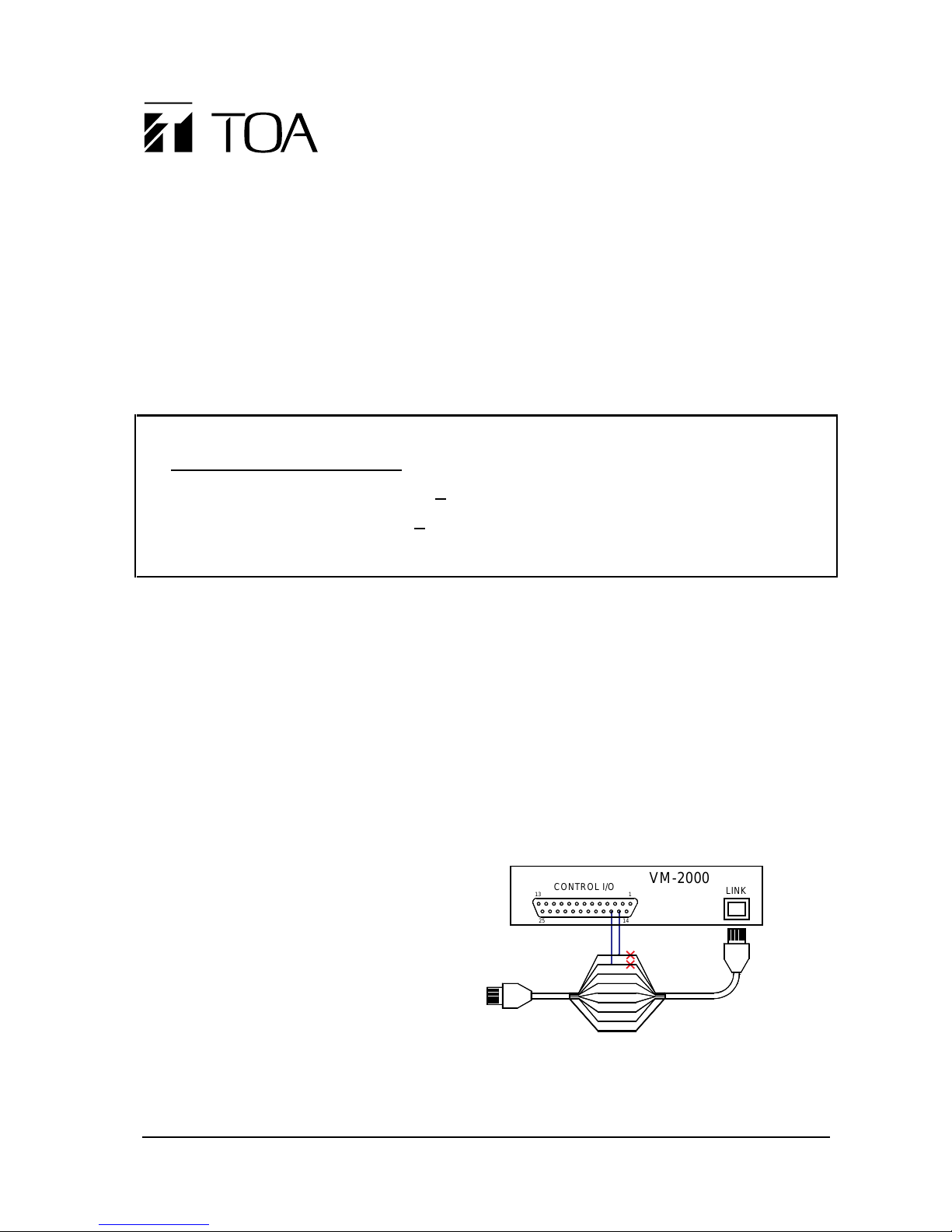
■ CONNECTION OF THE RM-200MS TO THE VM-2000
The wire connected to the pins 1 and 2 of the
RJ45 connector are used for the failure
control signal instead of power supply. So
these wires must be disconnected from the
VM-2000. Wire 1 (once connected to pin 1 of
the RJ45 connector) must be connected to pin
15 of the CONTROL I/O connector, and wire
2 to pin 16.
At the location of the VM-2000, the control
signal can be separated from the incoming
cable by using the VM-RJA board, and the
RJ45 connection to the VM-2000 can be done by a ready-made cable. The separated failure control
signal will be connected to the external failure input on the I/O CONTROL connector. Please refer to
the next page.
S
8
7
6
5
4
3
2
1
to RM-200MS
LINK
CONTROL I/O
VM-2000
1425
13 1
Page 2
2 TOA Electronics Europe GmbH
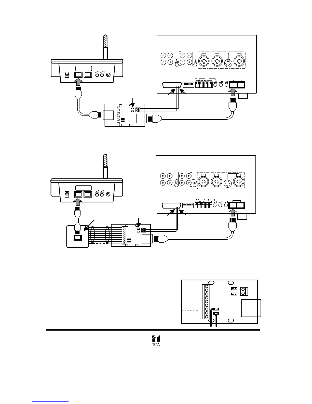
Using VM-RJA With Two RJ45 Connectors:
Any LINK connector of the VM-2000 and RM-200MS can be used.
Using VM-RJA With One RJ45 Connector And Screw Terminal:
Any LINK connector of the VM-2000 and RM-200MS can be used. The numbers printed next to the
screw terminal on the VM-RJA board correspond to the numbers of the RJ45 connectors.
Connection Of An External Power Supply
Remove the jumpers J3 and J4, and solder the power
supply’s wires to the PCB as shown right.
The connection to the RM-200MS and VM-2000 are as
shown above.
TOA Electronics Europe GmbH
Eiffestraße 74
20537 Hamburg
Tel.: (040) 25 17 19-0 * Fax: (040) 25 17 19-98
+
_
CONTROL I/O
BU2
J1
J3
J4
J2
Electronics Europe GmbH
manufactured for TOA
VM-RJA
RM-200MS
KL1
15
BU116VM
KL2
S
8
7
6
5
4
3
2
1
CONTROL I/O
BU2
J1
2
3
4
5
6
7
8
S
J3
J4
J2
Electronics Eur ope GmbH
manufactured for TOA
VM-RJA
1
RM-200MS
KL1
15
BU116VM
KL2
remove jumpers
J1 & J2
pin 15
pin 16
CONTROL I/O
LINK
RM-200MS
DC POWER IN
MIC
EXTERNAL
MIC IN
RM-200MS
CONTROL I/O
BU2
J1
J3
J4
J2
Electronics Europe GmbH
manufactured for TOA
VM-RJA
RM-200MS
KL1
15
BU116VM
KL2
S
8
7
6
5
4
3
2
1
remove jumpers
J1 & J2
pin 15
pin 16
CONTROL I/O
LINK
VM-2000
wall inlet
RM-200MS
DC POWER IN
MIC
EXTERNAL
MIC IN
RM-200MS
 Loading...