

Page 1
INSTRUCTION MANUAL
REMOTE MICROPHONE RM-1200
Please follow the instructions in this manual to obtain the optimum results from this unit.
We also recommend that you keep this manual handy for future reference.
Page 2

2
TABLE OF CONTENTS
1. SAFETY PRECAUTIONS ............................................................................................................... 3
2. GENERAL DESCRIPTION ............................................................................................................. 5
3. FEATURES ..................................................................................................................................... 5
4. HANDLING PRECAUTIONS .......................................................................................................... 5
5. NOMENCLATURE AND FUNCTIONS
Front Panel ...................................................................................................................................... 6
Bottom Panel
.................................................................................................................................................................... 7
Side Panel ....................................................................................................................................... 7
6. OPERATIONS
6.1. All-zone Broadcast ................................................................................................................... 8
6.2. Group Broadcast ...................................................................................................................... 9
6.3. Individual Zone Broadcast ...................................................................................................... 10
6.4. External Equipment Broadcast ...............................................................................................10
7. CONNECTIONS
7.1. Notes on Connections ............................................................................................................ 11
7.2. Connection of the RM-1200 to
the Rack-Mounted Emergency PA System
FS-971 Series
.................................................... 11
7.3. Connection of the RM-1200's Push-in Terminal Block ........................................................... 12
7.4. Error Message Indication ........................................................................................................ 12
8. INITIAL SETTING
8.1. Initial Setup ............................................................................................................................. 13
8.2. Address .................................................................................................................................. 13
8.3. Usable Group Numbers .......................................................................................................... 14
8.4. Individual Zone Broadcast ...................................................................................................... 14
8.5. Chime Tone Type ................................................................................................................... 14
8.6. Auto Chime Function .............................................................................................................. 15
8.7. Set Data Registration ............................................................................................................. 15
8.8. Termination of the Setting ...................................................................................................... 15
9. VOLUME LEVEL ADJUSTMENT ................................................................................................. 16
10. NAME LABEL REMOVAL AND REATTACHMENT .................................................................... 16
11. WALL MOUNTING ........................................................................................................................ 17
12. SPECIFICATIONS ........................................................................................................................ 18
Accessories ................................................................................................................................... 18
Page 3
3
1. SAFETY PRECAUTIONS
• Be sure to read the instructions in this section carefully before use.
• Make sure to observe the instructions in this manual as the conventions of safety symbols and messages
regarded as very important precautions are included.
• We also recommend you keep this instruction manual handy for future reference.
Safety Symbol and Message Conventions
Safety symbols and messages described below are used in this manual to prevent bodily injury and property
damage which could result from mishandling. Before operating your product, read this manual first so you are
thoroughly aware of the potential safety hazards as well as understand the safety symbols and messages.
When Installing the Unit
• Do not expose the unit to rain or an environment where it may be splashed by water or other liquids, as
doing so may result in fire or electric shock.
• Do not cut, kink, otherwise damage nor modify the connection cables. In addition, avoid using the cables in
close proximity to heaters, and never place heavy objects on the cables, as doing so may result in fire.
• Avoid installing or mounting the unit in unstable locations, such as on a rickety table or a slanted surface.
Doing so may result in the unit falling down and causing personal injury and/or property damage.
• Install the unit only in a location that can structurally support the weight of the unit and the mounting bracket.
Doing otherwise may result in the unit falling down and causing personal injury and/or property damage.
• To prevent the electromagnetic wave from badly influencing medical equipment, avoid installing the unit in
close proximity to the medical equipment.
When the Unit is in Use
• Should the following irregularity be found during use, immediately switch off the circuit breaker of the
junction panel to which the unit is connected. Then, contact your nearest TOA dealer. Make no further
attempt to operate the unit in this condition as this may cause fire or electric shock.
·If you detect smoke or a strange smell coming from the unit.
·If water or any liquid gets into the unit
·If the unit falls, or the unit case breaks
·If the connection cables are damaged (exposure of the core, disconnection, etc.)
• Do not place cups, bowls, or other containers of liquid on top of the unit. If they accidentally spill into the
unit, this may cause a fire or electric shock.
• Do not touch connection cables during thunder and lightning, as this may result in electric shock.
Indicates a potentially hazardous situation which, if mishandled, could
result in death or serious personal injury.
WARNING
Page 4

4
When Installing the Unit
• Avoid installing the unit in humid or dusty locations, in locations exposed to the direct sunlight, near the
heaters, or in locations generating sooty smoke or steam as doing otherwise may result in fire.
When the Unit is in Use
• Do not place heavy objects on the unit as this may cause it to fall or break which may result in personal
injury and/or property damage. In addition, the object itself may fall off and cause injury and/or damage.
• Do not stand on nor hang down from the unit as this may cause it to fall down or drop, resulting in personal
injury and/or property damage.
• Cut off the power supply (24 VDC) to the unit for safety purposes when cleaning or leaving the unit unused
for 10 days or more. A fire may result.
Indicates a potentially hazardous situation which, if mishandled, could
result in moderate or minor personal injury, and/or property damage.
CAUTION
Page 5

5
2. GENERAL DESCRIPTION
TOA's RM-1200 is a general-purpose remote control unit designed to be used in conjunction with TOA's FS971 Series Rack Mounted Emergency PA Systems. Featuring a built-in chime unit, the RM-1200 permits
group broadcast of up to 20 groups, simultaneous all-zone broadcast, and individual zone broadcast of up to
330 zones. First-in-first-out or Last-in-first-out priority can be assigned to individual units when connecting
multiple remote control units.
3. FEATURES
• Liquid crystal display facilitates check of broadcasting status, and initial setting.
• Individual zone broadcast of up to 330 zones (FS-971 Series).
• Uni-directional microphone suited for announcements.
• AUX input jack permits connection of a cassette deck or CD player.
• Internal compressor circuit prevents sound distortion due to large input.
(Functional only when the microphone is used.)
• Can be mounted on a wall.
4. HANDLING PRECAUTIONS
• Use the unit only with the voltage specified on the junction panel to which the unit is connected. Using a
voltage higher than that which is specified may result in equipment failure.
• To clean, wipe with a dry, soft cloth. Do not use benzine, thinner or chemically-processed towel because the
unit may be deformed or its finish discolored.
• When the case or operation panel is dirty, lightly wipe it down with a soft cloth. When it gets very dirty, wipe it
down with a wrung towel after dipping it in a neutral detergent diluted with water, then wipe with a dry cloth.
• Do not spray an insecticide or other volatile liquids over the unit. Avoid leaving the unit in contact with the
rubber or vinyl products for long hours because its quality may deteriorate or paint peel off.
Page 6
6
5. NOMENCLATURE AND FUNCTIONS
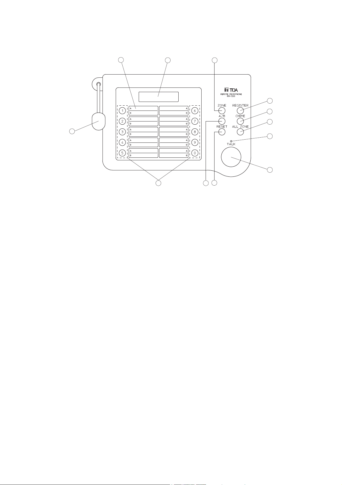
[Front Panel]
1. Talk key
Make announcements while holding down this key
when the message "In use" is displayed on the
screen (9).
Note
The key turns on when pressed, and turns off
when released.
2. In-use indicator
The attached microphone can be used when this
indicator lights.
3. All-zone broadcast key
Enables simultaneous broadcast to the entire area.
4. Reset key
Pressing this key terminates broadcast from the
main rack, and displays the indication "A" at the
upper right of the screen.
5. Chime key
Used to sound a chime. While the internal chime
is sounding, the in-use indicator flashes to indicate
that the microphone and AUX input have turned
off.
Note
The type of chime tone needs to be designated in
the initial setting. Refer to p. 14.
6. Group A/B selector key
Selects either Group A (A1-A0) or Group B (B1B0) when making group broadcast.
Note
If the number of groups is set for "10" in the initial
setting, only Group A can be selected.
7. Registration key
Registers the line number (broadcast zone)
selected with the numerical key to make
broadcast to individual zones.
8. Individual-zone mode selector key
Press this key first when selecting individual
broadcast zones.
Note
If the individual zone selection is set for "OFF" in
the initial setting, this key cannot be used.
9. LCD screen
Displays the state of broadcast or settings.
Backlight facilitates viewing even in dark
locations.
10. Name label/Label cover
Write the name of each broadcast zone. For the
removal and reattachment of the label and cover,
refer to the section "10. NAME LABEL
REMOVAL AND REATTACHMENT" on p. 16.
11. Microphone
12. Numerical key
Press this key to select individual broadcast
zones.
11
10
89
7
5
3
2
1
12
4
6
Page 7

7
13. Mode switch
Setting this switch to the ON position places unit
in the setting mode. Set this switch to the OFF
position after setting completion.
14. Connection terminal
Connect cables from the main rack to this
terminal. Refer to the section "7.
CONNECTIONS" on p. 11 for details.
15. AUX input jack (–20 dBV/100 kΩ)
Connect a cassette deck or CD player. Note
microphones cannot be connected.
16. Chime volume control
Adjusts the chime volume. Refer to the section
"9. VOLUME LEVEL ADJUSTMENT" on p. 16.
17. AUX input volume control
Adjusts the AUX input volume. Refer to the
section "9. VOLUME LEVEL ADJUSTMENT" on
p. 16.
18. Microphone volume control
Adjusts the microphone volume. Refer to the
section "9. VOLUME LEVEL ADJUSTMENT" on
p. 16.
[Bottom Panel]
[Side Panel]
13
14
15
16 1817
Page 8

8
6. OPERATIONS
• The TALK key turns on when pressed, and turns off when released.
• When the message "Other in use" is displayed on your remote control unit, if other message "In use" does
not appear even though you press the ALL ZONE, [1]-[0] or INDIVIDUAL ZONE key, this means the
equipment with higher priority is in use. Your unit cannot be used. Priority order is set at the main rack.
• When the unit is set for [Auto chime 1-4] in the initial setting, a chime is automatically sounded whenever the
TALK key is turned on and off.
• When the unit is set for [Auto chime 0] in the initial setting, press the CHIME key before and after
announcement if it is desirable to sound a chime.
• The In-use indicator flashes during internal chime play.
• For initial settings, refer to p. 13.
6.1. All-zone Broadcast
Press the ALL-ZONE key.
1.
To cancel the broadcast, press the RESET
key.
In seu
-
Al l Zone Cal l
Speak into the microphone holding down
2.
the TALK key. (The In-use indicator lights.)
Press the RESET key to terminate the
3.
announcement.
A
Page 9

9
6.2. Group Broadcast
[Simultaneous broadcast to both groups A and B]
1. Press the [1]-[0] (numerical) key to select the desired
broadcast group (1-0) of A.
2. Press the A/B group selector key and confirm that the
indication B is displayed at the upper right of the screen.
Press the numerical key to select the group of B.
3. Speak into the microphone while holding down the TALK key. (The In-use indicator lights.)
4. Press the RESET key to terminate the announcement.
Note
When [1. 10] is selected in the setting of "8.3. Usable Group Numbers" (p. 14), the indication A appears even if
the A/B key is pressed. Broadcast can be made only to the group (1-0) of A.
Press the [1]-[0] (numerical) key to select the
1.
desired broadcast group (1-0).
If the [1] key is pressed, this message appears.
In
A1 ,
To select multiple groups, press the
corresponding numerical keys continuously.
To cancel the entry, press the RESET key.
When selecting the group of [B], press the A/B
group selector key, and the indication [B] is
displayed at the upper right of the screen.
Then, press the [1]-[0] (numerical) key to
select the desired broadcast group (1-0).
If the [3] and [7] keys are pressed continuously,
this message appears.
In seuA
A1 , 3 , A7 ,A
If the [2] and [3] keys are pressed continuously,
this message appears.
seuA
B
In seuB
B2 , 3 ,B
Speak into the microphone while holding down
2.
the TALK key. (The In-use indicator lights.)
Press the RESET key to terminate the
3.
announcement.
In seuA
A1 , 3 , A7 ,A
In
A1 , 3 , A7 ,A
In
A1 , 3 , A7 , B2 , B3A,
seuB
seuB
Page 10

10
6.3. Individual Zone Broadcast
6.4. External Equipment Broadcast
1. Connect a cassette deck, CD player or other source equipment to the AUX input jack.
2. Follow the procedures of All-zone broadcast, Group broadcast or Individual zone broadcast to enable broadcast.
3. Operate the connected source equipment to make broadcast.
4. Press the RESET key to terminate the broadcast, then stop the operation of the connected equipment.
Note
When the TALK key is pressed to make a microphone announcement during external equipment broadcast,
both outputs are mixed together.
Press the INDIVIDUAL ZONE key.
1.
000
Press the [1]-[0] (numerical) key to select the
2.
desired speaker line number. To cancel the key
entry, press the RESET key and confirm that the
indication "000" is displayed.
If the [1] key is pressed, this indication is
displayed (Line No. 1).
010
If the [1][2] keys are pressed, this indication is
displayed (Line No. 12).
021
Press the REGISTRATION key.
3.
Notes
• To cancel individual zone broadcast in the
middle of entering the speaker line number,
press the RESET key twice.
• When the selected speaker line does not
exist, the message "Not Allocated" is
displayed.
In
Not Al located
se 0u00
In
012 ,
When selecting multiple speaker lines, repeat
Steps (2) and (3).
<Example>
Pressing [1] [Registration] [8] [Registration] [1] [2]
[Registration] displays the following indication.
In
001 008 , 012 ,,
Speak into the microphone while the TALK key
4.
is pressed. (The In-use indicator lights.)
Press the RESET key to terminate the announcement.
5.
se 0u00
se 0u00
A
Page 11

11
7. CONNECTIONS
7.1. Notes on Connections
• The maximum cable length between the main rack and the RM-1200 is 800 m.
• Use cables with line resistance of less than 10Ω.
• Use twisted paired cable for bus lines.
• Use twin shielded cables for signal lines.
• Be sure to connect the RM-1200's bus line to BUS 1 terminal.
• Be sure to match the polarity of bus lines.
7.2. Connection of the RM-1200 to the Rack-Mounted Emergency PA System
FS-971 Series
Connect the remote control unit to the Junction
Panel JP-0410 in the main rack. Up to eight
remote control units can be connected per
junction panel.
RM-1200 terminal block
1
H
Note
Do not connect E of the
C
24V
GND
phone plug to RM-1200.
Two-core shielded cable Twisted paired cable
C
E
H
To pre-amplifier
GND
24 V
CHIME
GEM RM PWR
GND
ACTI
112234 5 67 81910
IN USE
REMOTE
Observe correct polarity
of bus lines.
REMOTE
GND
GEN RM BUS
TIMER
GND GND
AUX CONTROL
PWR FAIL
CTRL
GND
11 12
JP-0410 front panel middle row terminal block
Page 12

12
7.3. Connection of the RM-1200's Push-in Terminal Block
1. Strip the cable sheath 9 mm using the strip gauge
provided on the side of the terminal block.
2. Insert the cable into the terminal block.
• Solid cable
Fully Insert the cable into the hole in the terminal
block.
• Twisted cable
Press the lock switch on the terminal block, and
fully insert the cable. Then, release the switch with
the cable inserted.
When removing the cable, pull it out of the terminal
block while pressing the lock switch.
Note : Do not press the lock switch extremely strong.
3. After connection completion, bundle cables
together using the cable clip, then fix the clip with
a screw.
If cables are too thick to be bundled together,
replace the cable clip with the supplied clip.
7.4. Error Message Indication
When error messages are displayed on the screen after connection and setting completion, the following
causes can be considered. Check the connections and settings again.
Strip gauge
9 mm
Lock switch
Cable clip
Note
Do not tighten the clip
extremely strong.
Error Message Indication
R
M-US E r r o rB
1. Bus line disconnection between the main rack and RM-1200
2. Reversed bus line polarity between the main rack and RM-1200
3. Connected RM-1200 numbers are set for "0" at the main rack.
Possible Cause
Po l ing Errorl
1. Wrong address setting at the RM-1200
2. Wrong setting of connected RM-1200 numbers at the main rack.
Page 13

13
8. INITIAL SETTING
Set the following items.
Factory-preset setting
• Address ................................................. 0
• Usable group numbers .......................... 2 (20 groups)
• Individual zone broadcast ...................... 1 (ON)
• Chime tone type .................................... 1 (4-note chime)
• Auto chime mode ................................... 0 (Off/disabled)
Placing the RM-1200's bottom-located Setting Mode Switch in the ON
position displays the Initial Setup screen.
8.1. Initial Setup
Pressing the [1] key and then the REGISTRATION key displays the
Address Setup screen.
Pressing the [2] key and then the REGISTRATION key produces
factory-preset data, and displays the message "Store?" (refer to p. 15
"8.7. Set Data Registration") on the screen.
8.2. Address
Be sure to set the address for "0" when using only one RM-1200 unit.
Up to eight RM-1200 units can be connected. Assign the address of
0-7 consecutively to each unit starting from "0". Take care not to
assign the same address to two or more units.
Using the numerical key, set the address of 0-7.
Press the REGISTRATION key, and the Group screen will be
displayed.
Setting Mode Switch
Ini ial Setupt1
1.S t 2. Ini t iael
Add ess Setupr0
0
If the [3] key is pressed, this indication is
displayed.
Add ess Setupr3
0
7
7
Page 14

14
8.3. Usable Group Numbers
Press either the [1] or [2] key to select group numbers used.
Note
If [1. 10] is selected, only up to ten groups of A1-A0 can be used.
The A/B key cannot be used.
Pressing the REGISTRATION key stores the selected group
numbers and displays the Individual Zone screen.
8.4. Individual Zone Broadcast
Press either the [1] or [2] key to set whether or not to disable (ON
or OFF) the Individual Zone Broadcast Function.
Note
If [2. OFF] (disabled) is selected, the INDIVIDUAL ZONE key
cannot be used.
Pressing the REGISTRATION key stores the setting and displays
the Chime type screen.
8.5. Chime Tone Type
Using the [1]-[5] keys, select the chime tone type to be played.
[1]: 4-tone chime
[2]: Two-tone chime
[3]: Single-tone chime
[4]: None
[5]: External chime
Note
The external chime refers to a chime component installed in
equipment connected to the RM-1200. Selecting [5. External
Chime] disables the Auto Chime Function.
Pressing the REGISTRATION key stores the selected chime tone
type and displays the Auto Chime screen.
GropNo.Setuu1p
1.1 2.200
If the [2] key is pressed, this indication is
displayed.
GropNo.Setuu2p
1.1 2.200
Ind v i dua l Zoni1e
1.O 2.OFFN
If the [2] key is pressed, this indication is
displayed.
Ind v i dua l Zoni2e
1.O 2.OFFN
Ch ietype
m
1
If the [5] key is pressed, this indication is
displayed.
Ch ietype
1
5
m
5
1
5
Page 15

15
8.6. Auto Chime Function
The Auto Chime Function automatically sounds a chime when the TALK
key turns on and off. However, if [5. External Chime] is selected in
5. Chime Tone Type Setting, the Auto Chime Function is disabled.
Using the [0]-[4] keys, set the operation mode.
[0]: Disables the Auto Chime Function.
[1]: TALK key ON → Ascending 4-note chime → Microphone turns on.
OFF → Microphone turns off. → Descending 4-note chime (*1)
[2]: TALK key ON → Ascending 4-tone chime → Microphone turns on.
OFF → Microphone turns off. → Announcement is terminated (*2).
[3]: TALK key ON → Designated chime tone → Microphone turns on.
OFF → Microphone turns off. (*1)
[4]: TALK key ON → Designated chime tone → Microphone turns on.
OFF → Microphone turns off. → Announcement is terminated (*2).
Further pressing the REGISTRATION key stores the designated Auto
Chime mode and displays the message "Store?".
8.7. Set Data Registration
To operate the unit exactly as set in Items 8.1.-8.6. above, select
[1. Yes], then press the REGISTRATION key. The termination message
is displayed.
To change set data, press the [2] key to select [2. No], then press the
REGISTRATION key. The display returns to the Initial Setup screen.
Make changes by following the procedures 8.1.-8.6.
8.8. Termination of the Setting
Set the Setting Mode Switch to the OFF position.
The setting is now complete. The display returns to the normal screen,
indicating that the unit is in normal operation mode.
Notes on operation
(*1) Press the RESET key to terminate announcements.
(*2) Announcements are automatically terminated.
Corresponding mode number
appears as the key is pressed.
Au tchimeo0
0.O F 1
4F
A
Set data registration
Stoe?r1
1.Y s 2.Noe
Termination message
Se t Setup SW.1
to OFF""
Setting Mode Switch
Page 16

16
9. VOLUME LEVEL ADJUSTMENT
1. Using the slotted screwdriver, turn the microphone, chime and AUX input volume controls fully counter-
clockwise.
2. Speaking into the microphone, turn the microphone volume control clockwise to adjust the volume.
3. Making broadcast from equipment connected to the AUX input, turn the volume control clockwise to adjust
the volume.
4. Sounding a chime, turn the chime volume control clockwise to adjust the volume.
(When using external chime unit, adjust the volume at the external unit.)
10. NAME LABEL REMOVAL AND REATTACHMENT
1. Insert a pointed object into the label cover opening and raise the cover to remove it.
2. Write broadcast zones in the label. When there are ten group broadcast groups, use the reverse side.
3. Replace the label and then the cover.
Microphone volume control
AUX input volume control
Chime volume control
Cover
Name label
Page 17

17
11. WALL MOUNTING
1. Remove the microphone mounting screw, then take the microphone out of the unit by lightly pulling.
2. After turning the microphone 90 degrees, reinsert it into the unit, then secure it with the screw.
3. Install the wall mounting bracket directly on the wall using the supplied wood screws.
4. Align holes in the RM-1200's bottom surface with bracket tabs, then slide the unit down into place.
Microphone
Mounting screw
Wall mounting bracket
Wood screws
Wall mounting bracket
Page 18

18
12. SPECIFICATIONS
Note : The design and specifications are subject to change without notice for improvement.
• Accessories
Cable clip ..................................................................... 1
Name label ................................................................... 1
Wall mounting bracket .................................................. 1
Wood screw (3.5 x 2.5) ................................................ 2
Power Source 24 VDC
Current Consumption 130 mA
Output 0 dBV, 600Ω, balanced
Microphone Uni-directional electret-condenser microphone
Speaker Control 20 groups, individual speaker line selection (up to 330 lines), all-zone broadcast
AUX Input -20 dBV, 100 kΩ, unbalanced
Chime Internal chime, 3 different tone types
Volume Control Microphone/AUX input/Chime volume controls
Connection Cable Twin shielded cable + twisted paired cable + power cable
Maximum Cable Length 800 m
Line Resistance Under 10Ω
Finish ABS resin, light gray
Dimensions 241 (w) x 51 (h) x 151 (d) mm
Weight 0.5 kg
Page 19

Page 20

133-02-00160-00
URL: http://www.toa.jp/
 Loading...