

Page 1
OPERATING INSTRUCTIONS
DIGITAL MIXER AMPLIFIER 2x240W
REMOTE CONTROLLER
MX-6224D
RC-03
MX-6224D
Thank you for purchasing TOA's Digital Mixer Amplier 2x240W and Remote Controller.
Please carefully follow the instructions in this manual to ensure long, trouble-free use of your equipment.
133-02-00236-02
Page 2

TABLE OF CONTENTS
1. SAFETY PRECAUTIONS
............................................................................. 3
2. GENERAL DESCRIPTION .......................................................................... 4
3. FEATURES ............................................................................................................ 4
4. RECOMMENDED SYSTEM ........................................................................ 5
5. HANDLING PRECAUTIONS ...................................................................... 6
6. INSTALLATION PRECAUTIONS ............................................................. 6
7. NOMENCLATURE AND FUNCTIONS ................................................. 7
7.1. MX-6224D Digital Mixer Amplifier 2x240W ............................................................ 7
7.2. RC-03 Remote Controller .................................................................................... 10
8. CONNECTION EXAMPLE ......................................................................... 11
9. CONNECTIONS ............................................................................................... 12
9.1. Microphone Connections .................................................................................... 13
9.2. External Auxiliary Equipment Connections ......................................................... 15
9.3. External Effector Connections ............................................................................ 15
9.4. Monitor Speaker Connections ............................................................................. 16
9.5. External Speaker Processor Connections .......................................................... 16
9.6. Speaker Connections .......................................................................................... 17
9.7. Extension Power Amplifier Connections ............................................................. 17
9.8. RC-03 Remote Controller Connections .............................................................. 18
10. SETTINGS ......................................................................................................... 19
10.1. Microphone Equalizer Settings .......................................................................... 19
10.2. Effector Settings ................................................................................................ 19
10.3. Speaker Equalizer Settings ............................................................................... 21
11. OPERATIONS .................................................................................................. 22
11.1. Making Broadcasts ............................................................................................ 22
11.2. Using Sleep Mode ............................................................................................. 24
11.3. Switching the AC Power OFF ............................................................................ 25
12. RACK MOUNTING ....................................................................................... 26
13. TROUBLE SHOOTING ............................................................................. 27
14. BLOCK DIAGRAM ....................................................................................... 28
15. SPECIFICATIONS ........................................................................................ 29
16. DIMENSIONAL DIAGRAM ..................................................................... 30
16.1. MX-6224D .......................................................................................................... 30
16.2. RC-03 ................................................................................................................ 30
2
Page 3
1. SAFETY PRECAUTIONS
• Before installation or use, be sure to carefully read all the instructions in this section for correct and safe
operation.
• Be sure to follow all the precautionary instructions in this section, which contain important warnings and/or
cautions regarding safety.
• After reading, keep this manual handy for future reference.
Safety Symbol and Message Conventions
Safety symbols and messages described below are used in this manual to prevent bodily injury and property
damage which could result from mishandling. Before operating your product, read this manual rst and
understand the safety symbols and messages so you are thoroughly aware of the potential safety hazards.
WARNING
CAUTION
Indicates a potentially hazardous situation which, if mishandled, could
result in death or serious personal injury.
Indicates a potentially hazardous situation which, if mishandled, could
result in moderate or minor personal injury, and/or property damage.
WARNING
When Installing the Unit
• Do not expose the unit to rain or an environment
where it may be splashed by water or other liquids,
as doing so may result in re or electric shock.
• Use the unit only with the voltage specied on
the unit. Using a voltage higher than that which is
specied may result in re or electric shock.
• Do not cut, kink, otherwise damage nor modify
the power supply cord. In addition, avoid using the
power cord in close proximity to heaters, and never
place heavy objects -- including the unit itself -- on
the power cord, as doing so may result in re or
electric shock.
• Be sure to replace the unit's terminal cover after
connection completion. Because the voltage of up
to 100 V is applied to the high impedance speaker
terminals, never touch these terminals to avoid
electric shock.
• Avoid installing or mounting the unit in unstable
locations, such as on a rickety table or a slanted
surface. Doing so may result in the unit falling
down and causing personal injury and/or property
damage.
• Since the unit is designed for indoor use, do not
install it outdoors. If installed outdoors, the aging of
parts causes the unit to fall off, resulting in personal
injury. Also, when it gets wet with rain, there is a
danger of electric shock.
• Apparatets stikprop skal tilsluttes en stikkontakt
med jord, som giver forbindelse til stikproppens
jord.
• Laite on liitettävä suojakoskettimilla varustettuun
pistorasiaan
• Apparatet må tilkoples jordet stikkontakt
• Apparaten skall anslutas till jordat uttag
When the Unit is in Use
• Should the following irregularity be found during
use, immediately switch off the power, disconnect
the power supply plug from the AC outlet and
contact your nearest TOA dealer. Make no further
attempt to operate the unit in this condition as this
may cause re or electric shock.
· If you detect smoke or a strange smell coming
from the unit.
· If water or any metallic object gets into the unit
· If the unit falls, or the unit case breaks
· If the power supply cord is damaged (exposure of
the core, disconnection, etc.)
· If it is malfunctioning (no tone sounds.)
• To prevent a re or electric shock, never open nor
remove the unit case as there are high voltage
components inside the unit. Refer all servicing to
qualied service personnel.
• Do not place cups, bowls, or other containers of
liquid or metallic objects on top of the unit. If they
accidentally spill into the unit, this may cause a re
or electric shock.
• Do not insert nor drop metallic objects or ammable
materials in the ventilation slots of the unit's cover,
as this may result in re or electric shock.
• Do not touch a power supply plug during thunder
and lightning, as this may result in electric shock.
3
Page 4

CAUTION
· Rack-mounting screws are not supplied with the
unit. Prepare them that are appropriate for the
equipment rack.
When Installing the Unit
• Never plug in nor remove the power supply plug
with wet hands, as doing so may cause electric
shock.
• When unplugging the power supply cord, be sure to
grasp the power supply plug; never pull on the cord
itself. Operating the unit with a damaged power
supply cord may cause a re or electric shock.
• When moving the unit, be sure to remove its power
supply cord from the wall outlet. Moving the unit
with the power cord connected to the outlet may
cause damage to the power cord, resulting in re or
electric shock. When removing the power cord, be
sure to hold its plug to pull.
• Do not block the ventilation slots in the unit's cover.
Doing so may cause heat to build up inside the
unit and result in re. Also, periodically clean the
ventilation slots of dust.
• Avoid installing the unit in humid or dusty locations,
in locations exposed to the direct sunlight, near the
heaters, or in locations generating sooty smoke
or steam as doing otherwise may result in re or
electric shock.
• To avoid electric shocks, be sure to switch off the
unit's power when connecting speakers.
When the Unit is in Use
• Make sure that the volume control is set to minimum
position before power is switched on. Loud noise
produced at high volume when power is switched
on can impair hearing.
• Switch OFF the unit's power before turning the
phantom power switch ON or OFF. Operating
the switch without switching OFF the main power
could result in a large transient noise through the
speakers, potentially resulting in speaker failure.
• Avoid using phantom power when connecting an
unbalanced microphone to the MIC 1 input, as the
microphone fails.
• Do not connect any other equipment than the RC03 Remote Controller to the MX-6224D’s Remote
controller connection port.
If other equipment, such as a PC, hub or network
device, is connected to that port, the connected
equipment could be damaged.
• Do not operate the unit for an extended period of
time with the sound distorting. Doing so may cause
the connected speakers to heat, resulting in a re.
• Contact your TOA dealer as to the cleaning. If dust is
allowed to accumulate in the unit over a long period
of time, a re or damage to the unit may result.
• Be sure to follow the instructions below when rackmounting the unit. Failure to do so may cause a re
or personal injury.
· Install the equipment rack on a stable, hard oor.
Fix it with anchor bolts or take other arrangements
to prevent it from falling down.
· When connecting the unit's power cord to an AC
outlet, use the AC outlet with current capacity
allowable to the unit.
• If dust accumulates on the power supply plug or
in the wall AC outlet, a re may result. Clean it
periodically. In addition, insert the plug in the wall
outlet securely.
• Switch off the power, and unplug the power supply
plug from the AC outlet for safety purposes when
cleaning or leaving the unit unused for 10 days or
more. Doing otherwise may cause a re or electric
shock.
2. GENERAL DESCRIPTION
The MX-6224D Dual 240W Mixer Power Amplier is designed for 2-zone Public address system suitable for
small to middle sized mosques application.
The optional RC-03 Remote Controller exclusively designed for use in conjunction with the MX-6224D permits
ON/OFF control of speaker zones and sound effect function.
3. FEATURES
• Dual 240 W digital amplier.
• 6 Microphone inputs and 2 AUX inputs.
• Independent input and output volume controls.
• Tone controls (Low, Middle and High).
• Speaker equalizer preset for BS-1030 and TC-631M/651M
• DSP multi-effect (4 types of Dome, Hall, Plate, and Delay)
• RC-03 Remote Controller connection
• Desktop and rack mountable design
4
Page 5
4. RECOMMENDED SYSTEM
To AC mains
MX-6224D
BS-1030B
Box speaker x 4
CD Player
DM-1300
Dynamic Microphones
EM-410
Electret condenser
Microphone
DM-1300
Dynamic Microphones
TC-631M
Horn speaker x 4
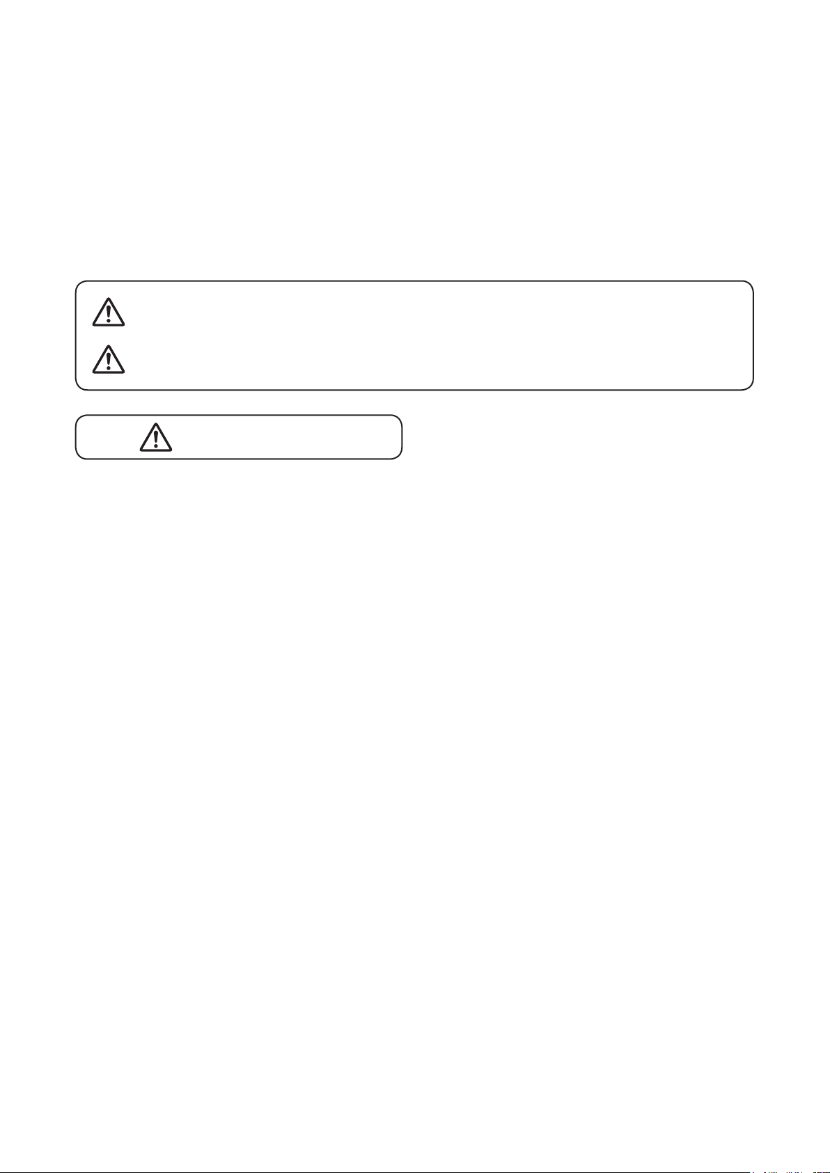
Ways of using MIC 2 − 4 and 5 − 6 are shown below as a guideline:
MIC 2: Mount on a high microphone stand.
Mic 5 and 6
MIC 3: Mount on a medium-height microphone stand.
MIC 4: Mount on a low microphone stand.
5
Page 6
5. HANDLING PRECAUTIONS
• The supplied power supply cord is designed to be used exclusively with the unit. Do not connect it to any other
equipment.
• Install the unit in locations where the temperature is between 0 and 40 °C and the moisture is between 35 and
80% (no dew condensation must be formed).
• The unit is a precision audio component. To prevent failure, avoid locations where the unit may be exposed
to strong shocks or vibrations.
• To clean, be sure to rst switch off the unit's power, then wipe with a dry cloth. Never use benzene, thinner,
alcohol, or chemically-treated cleaning cloth because such volatile liquids could deform or discolor the unit.
6. INSTALLATION PRECAUTIONS
• Be sure to install and connect the unit before the connection to the AC mains outlet. Remove the unit's power
supply cord from the AC mains outlet when uninstalling or disconnecting the unit.
• The socket-outlet shall be installed near the unit and the plug shall be easily accessible.
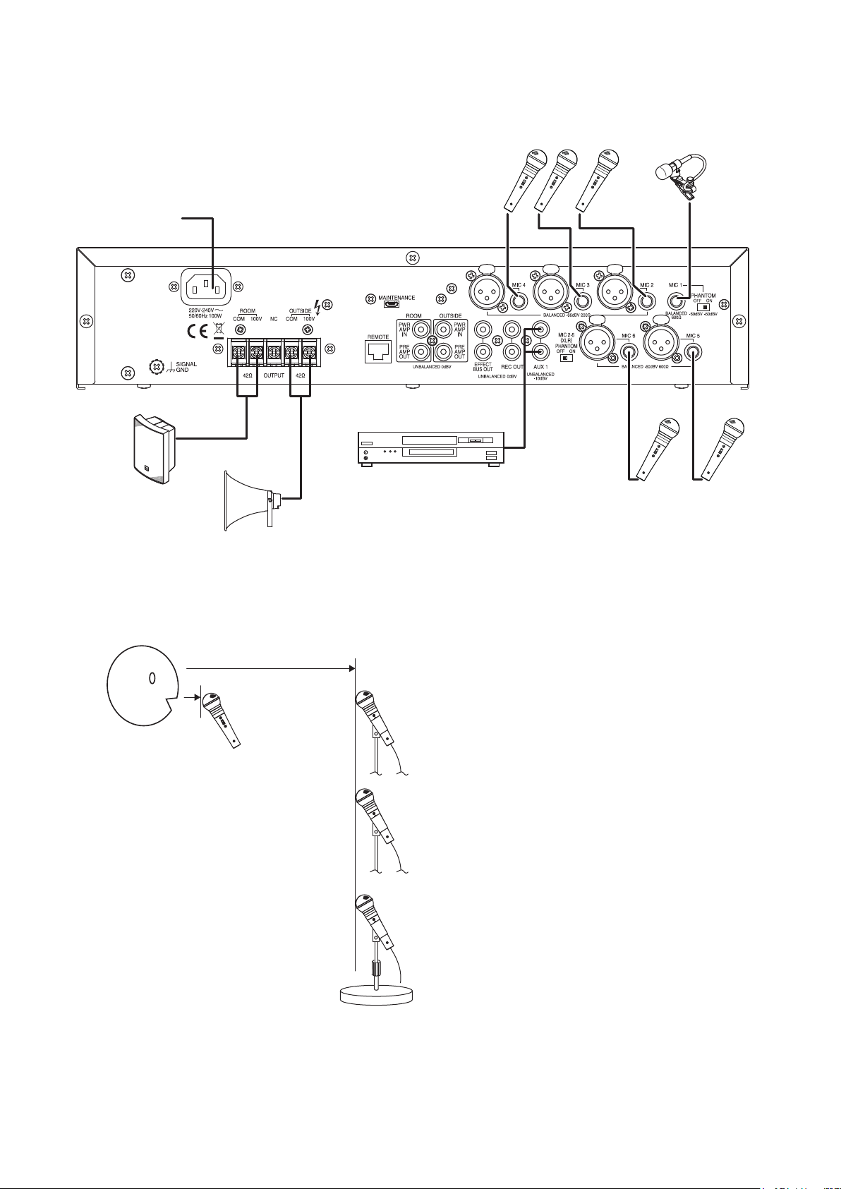
• Ensure that the unit is located at least 10 cm away from ceiling and wall surfaces, as shown in the gure
below, to allow adequate cooling and thus prevent extreme increases in temperature inside the unit. Also, do
not place any other devices within that range.
Over 10 cm
Over 10 cmOver 10 cm
6
Page 7
7. NOMENCLATURE AND FUNCTIONS
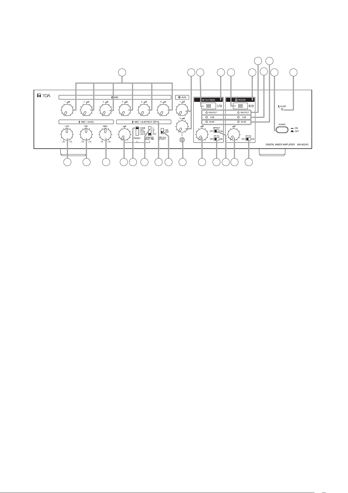
7.1. MX-6224D Digital Mixer Amplifier 2x240W
[Front]
12 13 14 15 16 17 18 19 20
1. Power switch
Turns on and off the main power.
2. Sleep indicator
Lights green when the power switch is ON and
the unit is placed in sleep mode.
3. Microphone volume controls
Adjust each microphone input.
4. AUX 1 and 2 volume controls
Adjust the AUX 1 and 2 inputs.
5. Outside zone output switch
Turns on and off the outside zone output.
9
11
10
1
22 23 24 25
21
the point where the red indicator (0 dB) begins to
light.
11. Signal level indicator (–20 dB)
Lights green when the power amplier's output
level is –20 dB referenced to 0 dB at rated output
(100 V).
12. Low frequency control (80 Hz)
Turn the control knob clockwise to enhance low
frequencies and counterclockwise to weaken
them. The frequency is at at the center position.
Note
This Equalizer control will not affect the AUX 1
and 2 inputs.
23 4 5 6 7 8
6. Outside zone output indicator
Lights red when sound is output from the Outside
zone output terminals (34).
7. Room zone output switch
Turns on and off the room zone output.
8. Room zone output indicator
Lights green when sound is output from the Room
zone output terminals (33).
9. Protection indicator
Lights red when the following situations are
detected.
• Built-in digital amplier failure
• Overcurrent ow inside the unit
• Overheat inside the unit
• Speaker output failure
• Excessive input of low frequency signals
10. Peak level indicator
Lights red when the output sound level reaches
the peak level (0 dB) referenced to 0 dB at rated
output (100 V).
In general use, each volume should be set below
13. Middle frequency control (2.5 kHz)
Tur n the control knob clock wise to enhance middle
frequencies and counterclockwise to weaken
them. The frequency is at at the center position.
Note
This Equalizer control will not affect the AUX 1
and 2 inputs.
14. High frequency control (12 kHz)
Turn the control knob clockwise to enhance the
high frequencies and counterclockwise to weaken
them. The frequency is at at the center position.
Note
This Equalizer control will not affect the AUX 1
and 2 inputs.
15. Effe ct control
Adjusts effect response.
Turn the control knob clockwise to strengthen the
response of the effect selected by the Effect preset
type selection switch (16), and counterclockwise
to weaken it.
Turning the control fully counterclockwise
provides no effect response.
7
Page 8
16. Effect preset type selection switch
Select the type of the sound effect from "DOME,"
"HALL," "PLATE," and "DELAY."
17. Effect Room size/Delay time selection switch
Select the reverberation/delay time of effect from
"S" (Short time), "M" (Medium time), and "L" (Long
time).
When set to OFF, the effect function is disabled.
18. Effect indicator
Lights green when the built-in effector is activated.
19. MIC 5 – 6 effect switch
Turns on and off the effect for the MIC 5 and 6
inputs.
Note
Effect for the MIC 1 to 4 inputs is constantly ON.
20. AUX 2 input jack
–20 dB*, 10 kΩ mixed monaural, unbalanced,
ø3.5 mm mini jack (3P: stereo)
Connects to an external music player.
21. Volume control for the outside zone
Adjusts the outside zone output level.
22. Equalizer switch (Horn speaker)
Set this switch to the ON position to optimize
the output sound for the TOA TC-631M/651M
speaker.
23. Outside zone output effect switch
Turns on and off the effect for the Outside zone
output.
Note
Effect for the Room zone output is constantly ON.
24. Volume control for the room zone
Adjusts the room zone output level.
25. Equalizer switch (Box speaker)
Set this switch to the ON position to optimize
the output sound for the TOA BS-1030B/1030W
speaker.
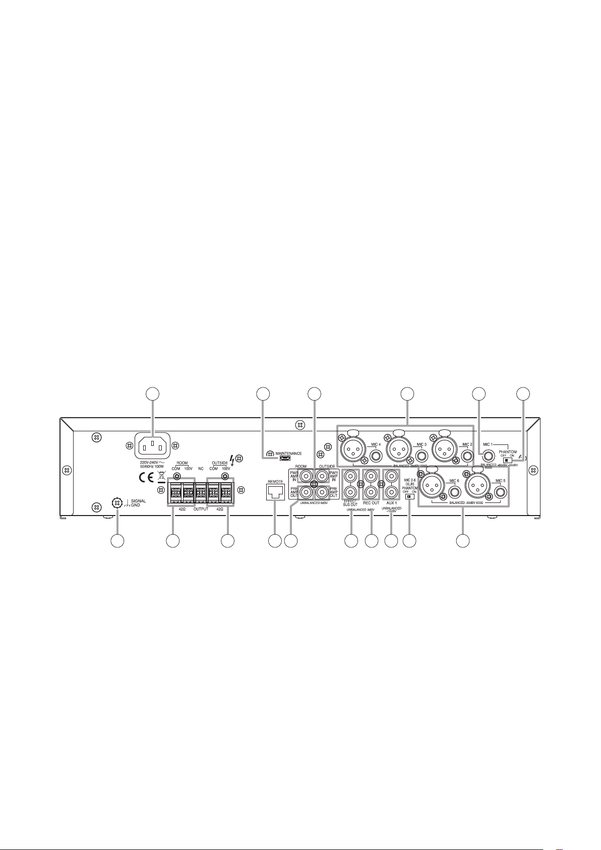
[Rear]
26 27 28 29 30
32 33 34 35 36 37 38 39 40
26. AC inlet
Connects to the AC power source using the
supplied AC power supply cord.
Note
Connect the AC power supply cord to a grounded
AC outlet.
27. Mainte nance p ort
For service personnel use only.
28.Poweramplierinputjacks
0 dB*, 10 kΩ, unbalanced, RCA pin jacks
Connect to an external speaker processor.
29. MIC 2 – 4 input jacks/XLR type connectors
–66 dB*, 200 Ω, electronically-balanced
Use either the phone jack or XLR type connector
for each MIC input.
41
Connect to the balanced type microphone, suitable
for on microphone application. A balanced type
dynamic microphone can be connected to each
phone jack input. For the microphones connected
to each XLR type input, see "40. MIC 2 – 6 (XLR)
phantom switch."
30. MIC 1 input jack
(
24 V
–50 dB*
power OFF),
mm phone jack
Connects to the balanced type microphone,
suitable for off microphone application (a lavaliere
microphone is recommended).
For the connectable microphones, see "31. MIC 1
phantom switch."
p ha nt o m po we r e d )/
600 Ω
, electronically-balanced, ø6.3
–60 dB*
* 0 dB = 1 V
31
phantom
8
Page 9

31. MIC 1 phantom switch
When switched ON, phantom power is supplied
to the MIC 1 input. Microphones connected to
the MIC 1 input depend on the switch setting as
follows.
ON: A balanced type phantom powered
condenser microphone can be connected.
OFF: A balanced type dynamic microphone can
be connected.
37. Effect bus output jacks
0 dB*, 600 Ω monaural, unbalanced, RCA pin
jacks (1 pair)
Connect to an external sound effector.
38. Recording output jacks
0 dB*, 600 Ω monaural, unbalanced, RCA pin
jacks (1 pair)
Connect to a sound recorder.
IMPO RTANT
Never use an unbalanced TS connector (sleeve
and ring connected) for connection to the MIC 1
input jack if you want to use the phantom power
supply.
Note
Before switching on the phantom power, be
sure to turn the MIC 1 volume control (3) fully
counterclockwise. Otherwise a switching noise
may be produced, possibly damaging the unit.
32. Functional ground terminal
Hum noise may be generated when external
equipment is connected to the unit. Connecting
this terminal to the functional ground terminal
of the external equipment may reduce the hum
noise.
Note
This terminal is not for protective ground.
33. Room zone output terminals [100 V Line]
Galvanic isolated balanced, M4 screw terminal
Connect to the 100 V line type speaker for the
room zone.
34. Outside zone output terminals [100 V Line]
Galvanic isolated balanced, M4 screw terminal
Connect to the 100 V line type speaker for the
outside zone.
35. Remote controller connection port
Connects to an optional RC-03 Remote Controller.
39. AUX 1 input jacks
–10 dB*, 10 kΩ mixed monaural, unbalanced,
RCA pin jacks (1 pair)
Connect to external auxiliary equipment.
40. MIC 2 – 6 (XLR) phantom switch
When switched ON, phantom power is supplied
to the XLR type connectors of MIC 2 – 6 inputs.
Microphones connected to the XLR type inputs
depend on the switch setting as follows.
ON: A balanced type phantom powered
condenser microphone can be connected.
OFF: A balanced type dynamic microphone can
be connected.
Note
Before switching on the phantom power, be sure
to turn the MIC 2 – 6 volume controls (3) fully
counterclockwise. Otherwise a switching noise
may be produced, possibly damaging the unit.
41. MIC 5 and 6 input jacks/XLR type connectors
–60 dB*, 600 Ω, electronically-balanced
Use either the phone jack or XLR type connector
for each MIC input.
Connect to the balanced type microphone,
suitable for on or off microphone application.
A balanced type dynamic microphone can be
connected to each phone jack input. For the
microphones connected to each XLR type input,
see "40. MIC 2 – 6 (XLR) phantom switch."
* 0 dB = 1 V
36.Preamplieroutputjacks
0 dB*, 600 Ω monaural, unbalanced, RCA pin
jacks
Connect to an external power amplier or an
external speaker processor.
9
Page 10
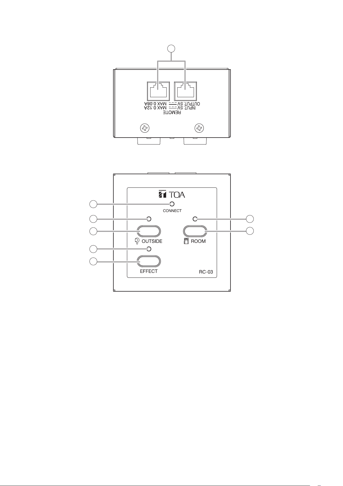
7.2. RC-03 Remote Controller
[Top]
[Front]
1
2
3
4
5
6
1. Control line connection ports
Equipped with 2 RJ-45 ports.
Connect either of the 2 ports to the MX-6224D
amplier.
Maximum cable length is 200 m.
Use STP or UTP Category 5 straight cable for LAN
with RJ-45 connectors.
Note
Do not use crossover cable.
2. Connection indicator
Lights green when the Remote Controller is
connected to the MX-6224D and the power switch
of MX-6224D is ON.
3. Outside zone indicator
Lights red when sound is output to the outside
zone.
7
8
4. Outside zone switch
Turns on and off the outside zone output.
5. Effect indicator
Lights green when effector is enabled.
6. Effect switch
Turns on and off the effector.
7. Room zone indicator
Lights green when sound is output to the room
zone.
8. Room zone switch
Turns on and off the room zone output.
10
Page 11
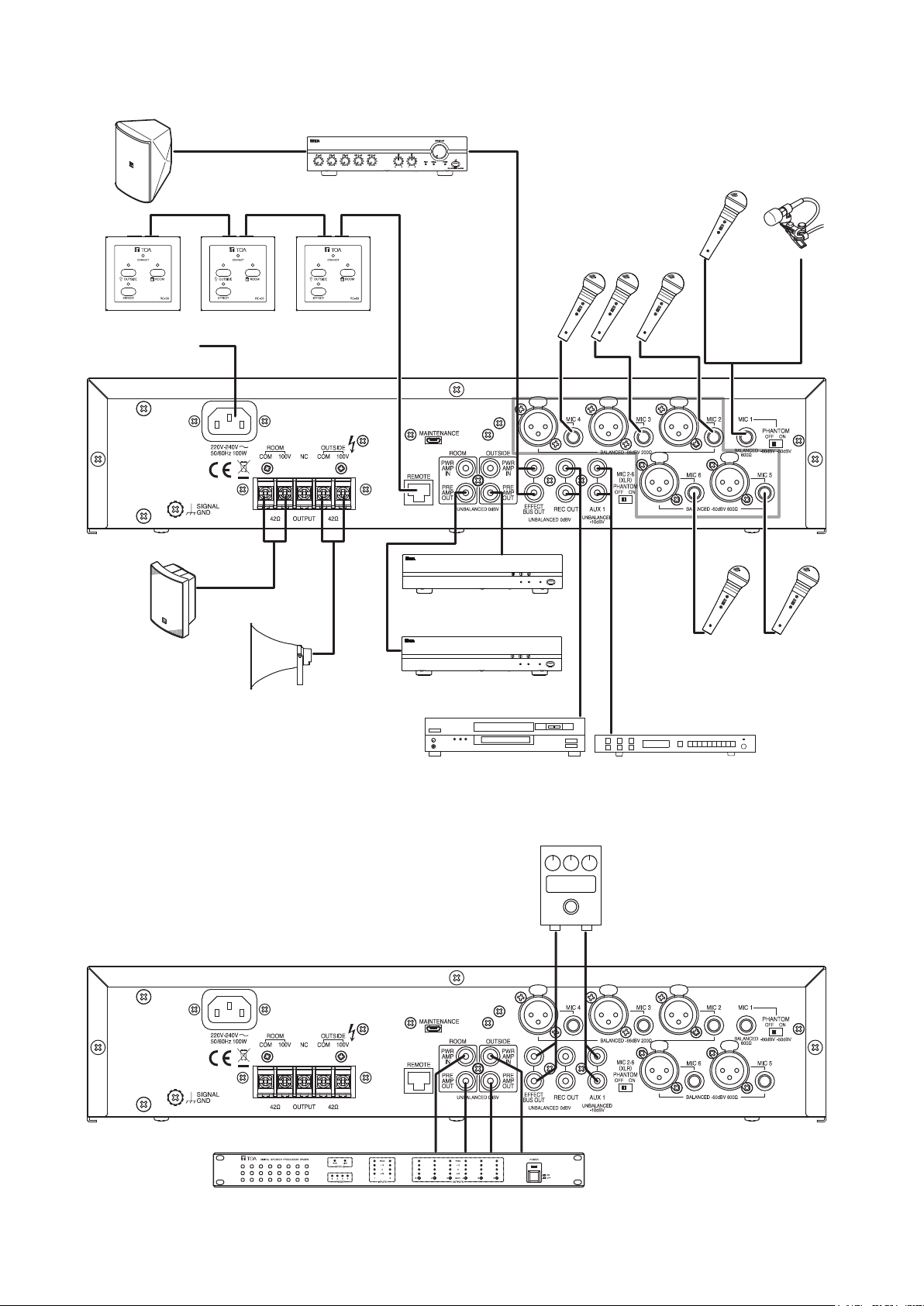
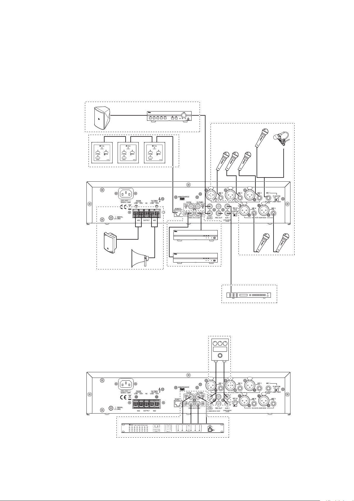
8. CONNECTION EXAMPLE
F-1300B
Monitor speaker
A-2030
Mixer amplifier
DM-1300 (phantom swictch is OFF) or
EM-410 (phantom swictch is ON)
Microphone
DM-1300
Dynamic
Microphones
or
RC-03
To AC mains
MX-6224D
BS-1030B
Box speaker x 4
RC-03
RC-03
Remote controller
TC-631M
Horn speaker x 4
P-2240
Power amplifier
P-2240
Recorder
DM-1300
Dynamic
Microphones
Radio tuner or CD player
[Connection when signal processing equipment is used]
MX-6224D
InOut In Out
DP-SP3
Speaker processor
Effector
In Out
11
Page 12
9. CONNECTIONS
Note
Always be sure that the power is switched OFF before connecting the unit. After connection is completed, be
sure to set all volume controls to their minimum level (fully rotated counterclockwise) before switching the power
ON again.
Monitor Speaker connections (see p. 16)
Microphone connections
(see p. 13)
Remote Controller
connections
(see p. 18)
Speaker connections
(see p. 17)
or
External Power Amp
connections (see p. 17)
External Auxiliary Equipment
connections (see p. 15)
12
External Effector connections
(see p. 15)
MX-6224D
External Speaker Processor connections (see p. 16)
Page 13
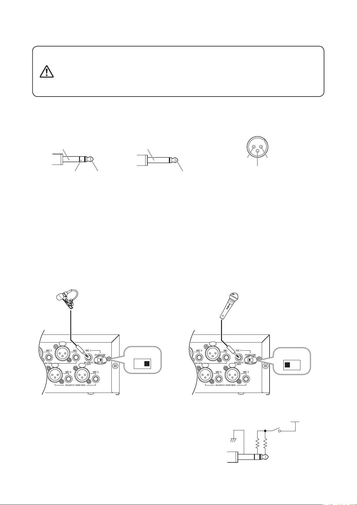
9.1. Microphone Connections
+24 V
• Switch OFF the unit's power before turning the phantom power switch
ON or OFF. Operating the switch without switching OFF the main
CAUTION
9.1.1. About the pin arrangement of the microphone input jack
Refer to the gure below when connecting the microphone input plug and connector:
[Phone plug] [XLR type connector (male)]
Sleeve: Ground
Ring: Cold Tip: HotTip: Hot
9.1.2. MIC 1 connections
power could result in a large transient noise through the speakers,
potentially resulting in speaker failure.
• Avoid using phantom power when connecting an unbalanced
microphone to the MIC 1 input, as the microphone fails.
• Unbalanced type• Balanced type
Sleeve: Ground
Pin 1: Ground Pin 2: Hot
Pin 3: Cold
Microphones equipped with a phone plug can be connected to the MIC 1 input jack.
• Both balanced and unbalanced microphones can be used.
• Turning the phantom power switch ON causes a 24 V voltage to be applied to the phone plug's tip and ring.
• When using a lavalier microphone, it is recommended that TOA's EM-410 Lavalier Microphone be used.
Microphone sensitivity when phantom power is used or unused is as follows:
When used: −50 dB*
When not used: −60 dB*
*
0 dB = 1 V
[When phantom power is used] [When phantom power is not used]
EM-410
Electret condenser microphone
DM-1300
Dynamic microphone
OFF ON
OFF ON
Note
Use only balanced phone plugs when connecting a condenser
microphone that requires phantom power to MIC 1.
phantom power
MIC 1
phantom switch
– ++
13
Page 14
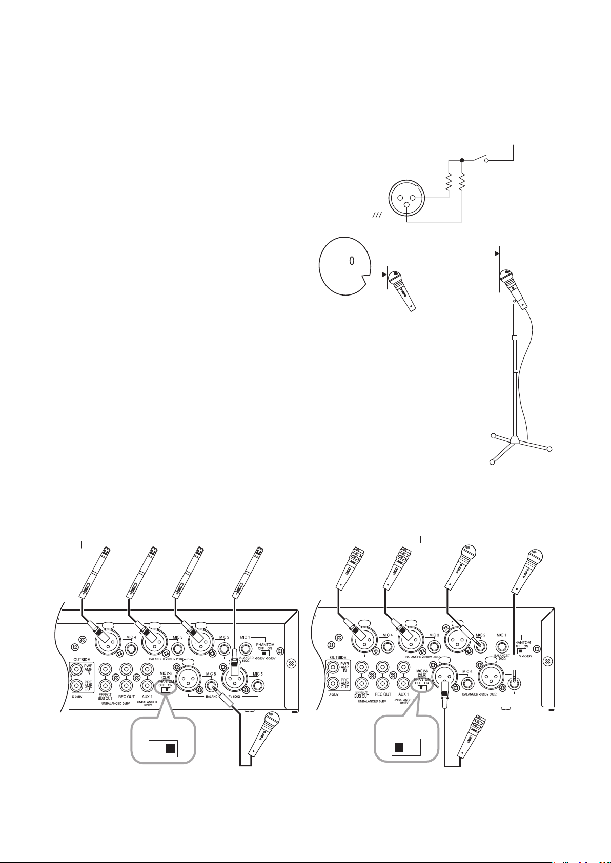
9.1.3. MIC 2 – 6 connections
Microphones equipped with either an XLR connector or a phone plug can be used with microphone inputs 2 – 6.
• Balanced or unbalanced microphones can be connected to the phone jack.
• Switching ON the phantom power switch supplies power to all MIC 2 – 6 XLR connectors.
• No phantom power is supplied to the MIC 2 – 6 phone jacks.
+24 V
Tip
phantom power
When phantom power is used for the MIC 2 – 6 XLR connectors,
a 24 V voltage is applied to Pins 2 and 3 in each connector.
1 2
3
+
MIC 2 − 6
phantom switch
–
+
Microphone sensitivity is as follows:
MIC 2 – 4: −66 dB (high sensitivity)
MIC 5 – 6: −60 dB
MIC 2 − 4
For microphones connected to MIC 2 – 4, it is assumed
that the microphone will be mounted on a microphone
stand and use d at a distance from the speaker's mo uth.
For microphones connected to MIC 5 or 6, it is assumed
MIC 5, 6
that the microphone will be used close to the speaker's
mouth.
Note
Do not simultaneously connect microphones to the XLR connector and the phone jack of the same number.
Input signals to the microphone input may be attenuated, potentially disabling normal use of these connectors.
[When phantom power is used] [When phantom power is not used]
Electret condenser microphones
Dynamic microphones
DM-1300 DM-1300
OFF ON
Note
In this gure, since a microphone with a phone plug is
used for MIC 6 input, the phantom power is not supplied.
14
DM-1300
Dynamic microphone
OFF ON
Dynamic microphone
Page 15
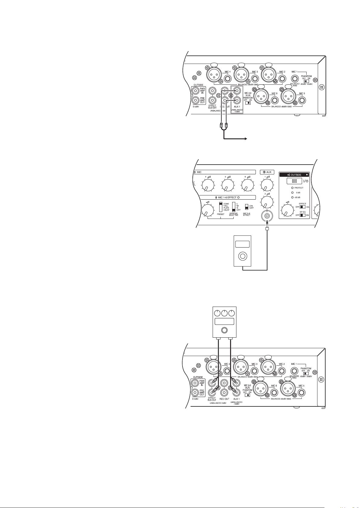
9.2. External Auxiliary Equipment Connections
9.2.1. AUX 1 input jack connections
Two input signals can be mixed within the unit. For
stereo sound source wiring, connect to both RCA pin
jacks. For monaural sound source wiring, connect to
either jack.
9.2.2. AUX 2 input jack connections
Signal inputs to the stereo mini jacks are mixed
within the unit. For stereo sound source wiring, use
a stereo mini plug for connection. For connection to
a monaural sound source, use either a monaural or
stereo mini plug.
To external auxiliary equipment
9.3. External Effector Connections
An external effector can be connected without using
the unit's internal effector function (see p. 19). If
the Effect Room Size/Delay Time Selection Switch
is switched OFF, the internal effector is disabled, but
external effectors can still be used. Even when using
an external effector, the effect on MIC 5 and 6 can be
cut off with the MIC 5 and 6 effect switches.
Tips
• For information on effector use, see the instruction
manual enclosed with the effector.
• The internal effector can also be used while the
external effector is connected. Using both effectors
at the same time will result in both effects being
mixed.
Music player, etc
Effector
In Out
15
Page 16
9.4. Monitor Speaker Connections
Ampliers and speakers for monitoring applications can be connected using the effect bus output jack.
A-2030
Mixer amplifier
Monitor speaker sound volume is not interlocked with the outside and room volume controls located on the
front panel, but is instead interlocked with the effect volume control. When using both the monitor speaker and
internal effector, adjust the effect volume control rst, then adjust the sound volume with the volume control of
the amplier for monitoring.
Tips
• Output from the effect bus output jack is not interlocked with the front panel-mounted outside and room
volume controls.
• For more information on using the amplier for monitoring, see the instruction manual enclosed with the
amplier.
F-1300B
Monitor speaker
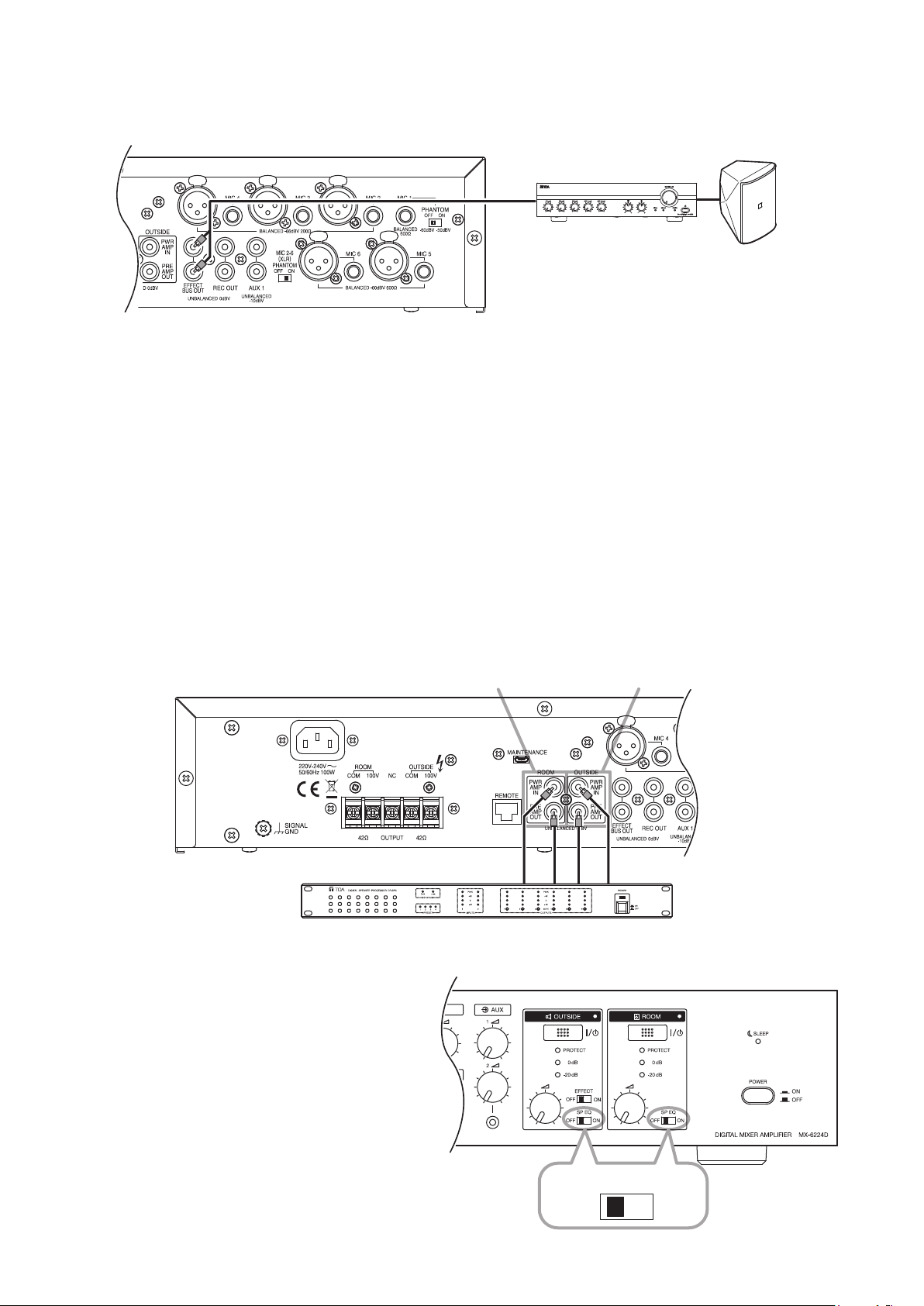
9.5. External Speaker Processor Connections
TOA's DP-SP3 Digital Speaker Processor can be used as an external speaker processor without using the
unit's internal speaker equalizer function (see p. 21). The external speaker processor can also be used for
either the ROOM or OUTSIDE speakers.
For more information on use of the DP-SP3 processor, see the instruction manual enclosed with the DP-SP3.
For ROOM zone For OUTSIDE zone
InOut In Out
DP-SP3 Digital speaker processor
Note
Turn the Equalizer switch OFF for zones using the
DP-SP3 Digital Speaker Processor. If not turned
OFF, the effects produced by both the external
and internal effectors will be applied and optimum
sound quality adjustment cannot be achieved.
16
OFF
SP EQ
ON
Page 17
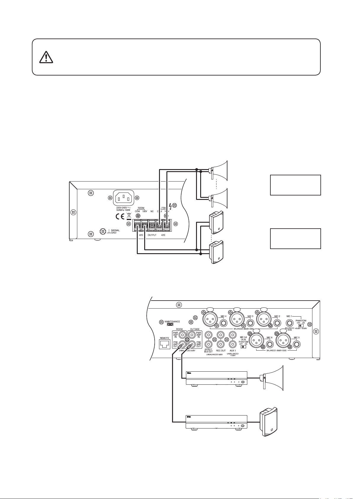
9.6. Speaker Connections
Be sure to reattach the terminal cover after connections are completed.
WARNING
Notes
• Connect only high-impedance 100 V line speakers to the unit. Connection of low-impedance speakers could
cause amplier failure.
• Carry out connections so that the total impedance at each speaker terminal is greater than the value shown
in the gure below (42 Ω). If the impedance is smaller than the indicated value, the amplier could fail.
Tips
• The unit is designed for a total impedance to be greater than the indicated value (42 Ω) when high-impedance
100 V line speakers are connected to each speaker terminal and the total wattage is less than 240 W.
• The unit can produce optimum sound quality conditions when the following TOA speakers are connected and
the speaker equalizer function is used. (see p. 21.)
For ROOM zone: BS-1030B, BS-1030W
For OUTSIDE zone: TC-631M, TC-651M
Failure to do so could result in electrical shocks, as a high voltage is
applied to the speaker terminals. Also, take care to NEVER touch the
speaker terminals.
MX-6224D
OUTSIDE zone
Horn speaker
ROOM zone
Box speaker
Total impedance:
42 Ω or more
Total impedance:
42 Ω or more
9.7. Extension Power Amplifier Connections
The unit is designed for connection to high-impedance 100 V line speakers, adding up to a total wattage of
240 W each for OUTSIDE and ROOM use. However, if more speakers are required, the power amplier can
be extended.
The sound volume of speakers connected
to the extension power amplier is not
interlocked with the front panel-mounted
outside and room volume controls.
Adjust the volume using the extension
power amplier's volume control.
Tips
• Output from the preamplier output jacks is
not interlocked with the front panel-mounted
outside and room volume controls.
• Output from the preamplier output jacks is
interlocked with the outside and room zone
output switches.
• Since the speaker equalizer affects output
from the preamplier output jacks, connect the
designated speakers (see p. 21.) to the power
amplier when the speaker equalizer switch is
ON for the zone(s).
• For more information on connecting speakers to
the extension amplier and use of the extension
amplier, see the instruction manual enclosed
with the amplier.
P-2240
Power amplifier
P-2240
OUTSIDE zone
Speaker
ROOM zone
Speaker
17
Page 18
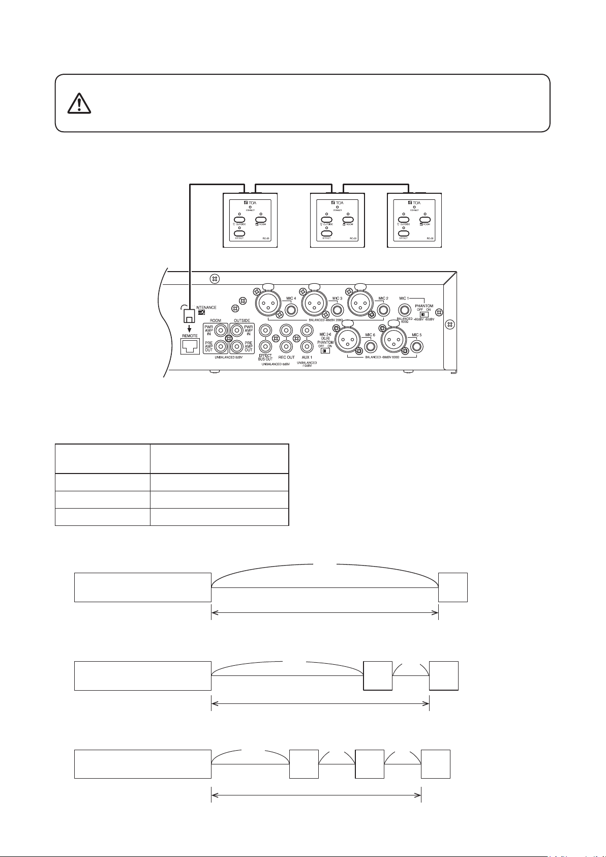
9.8. RC-03 Remote Controller Connections
Do not connect any other equipment than the RC-03 Remote Controller
CAUTION
Up to three RC-03 controllers can be connected to the unit.
The RC-03 has two connection ports, which permit connection in daisy chain fashion. Both ports can be used.
to the MX-6224D’s Remote controller connection port.
If other equipment, such as a PC, hub or network device, is connected
to that port, the connected equipment could be damaged.
Remote controller
RC-03
RC-03RC-03
Use STP or UTP Category 5 straight cable for LAN with RJ-45 connectors for connection.
Note
Do not use crossover cable.
The total permissible cable extension distance is as follows:
No. of Connected
RC-03 Units
Total Extension Distance*
*1 When using a cable with the following specications:
1
• STP Category 5 straight cable
• AWG 24
1 200 m or less
2 Total of 115 m or less*
3 Total of 80 m or less*
2
2
• Cable resistance (one way): 93.8 Ω/km
*2 This table refers to the total length of cable between
the unit and the RC-03, and between RC-03 units.
There are no restrictions on the distance between
devices.
18
(When one RC-03 unit is connected:)
MX-6224D
Under 24 Ω (one way)
(a)
(When two RC-03 units are connected:)
(a)
MX-6224D RC-03
Under 12 Ω (one way)
(When three RC-03 units are connected:)
MX-6224D
(a)
RC-03 RC-03 RC-03
Under 8 Ω (one way)
(b) (c)
(b)
RC-03
RC-03
(a) + (b) + (c)
(a)
≤ 200 m
(a) + (b) ≤ 115 m
≤ 80 m
Page 19

10. SETTINGS
After connection completion, perform settings while sound is actually being broadcasting (see p. 22).
MX-6224D
Microphone Equalizer
settings (see below)
Effector settings
(see below)
Speaker Equalizer settings
(see p. 21)
10.1. Microphone Equalizer Settings
The equalizer settings of MIC 1 – 6 can be adjusted to low, middle and high frequency bands. Rotating the
Frequency Control knob of each band clockwise enhances the relevant band, while counterclockwise rotation
weakens the band.
Note
The equalizer settings of AUX 1 and 2 inputs cannot be adjusted.
Tip
Each frequency band's center frequency is as follows:
Low frequency band: ±15 dB, 80 Hz
Middle frequency band: ±15 dB, 2.5 kHz
High frequency band: ±15 dB, 12 kHz
Weakens Enhances
10.2. Effector Settings
The unit’s built-in effector function offers a range of settings.
The effector is enabled whenever the Effect Room Size/Delay Time Selection switch is set to any other position
than OFF. When enabled, the effector is applied to each input and output as follows:
Input Output
Always enabled
Enabled or disabled
(selectable)
Cannot be enabled
Note
The effector is not applicable to source signals input from AUX 1 and 2.
Mic 1 − 4
Mic 5, 6
MX-6224D
AUX 1, 2 ROOM zone
OUTSIDE zone
Enabled or disabled
(selectable)
Always enabled
19
Page 20

10.2.1. Effector types and settings
MX-6224D
1 23
Step 1. Select the type of effect to be used with the Effect Preset Type Selection switch.
Refer to the following table for the types of effects that can be selected:
Effect Name Effect Description
DOME Creates an effect of stone walls with semi-domed ceilings.
HALL Creates an effect of wooden walls with carpeted oors.
PL ATE Creates an effect of metallic reverberation as by a metal plate hung from
the ceiling, accompanied by an extended high frequency band.
DELAY Creates an effect of sound being repeatedly reected following a delay.
Step 2. Enable or disable (ON/OFF) the effector, and select the reverberation time and delay time conditions
using the Effect Room Size/Delay Time Selection Switch.
DOME, HALL or PLATE settings DELAY settings
L Long reverberation time Long delay time
M Medium reverberation time Medium delay time
S Short reverberation time Short delay time
OFF Effector disabled. Effector disabled.
Step 3. Adjust the effector's response strength.
To adjust, rotate the Effect Control Knob. The effect becomes more pronounced as the knob is rotated
clockwise, and weakens as the knob is rotated counterclockwise.
10.2.2. Effector settings for MIC 5 and 6 inputs
The effector can be enabled or disabled (ON/OFF) for Microphone 5 and 6 inputs (default setting: OFF).
Step: To apply the sound effect to these inputs, set their Effect switches
to the ON position.
The following table shows the effector status of each input when
MIC 5 and 6 Effect switches are set to the ON or OFF position:
20
OFF ON
MIC 1–4 Effector enabled Effector enabled
MIC 5 and 6 Effector disabled Effector enabled
AUX 1 and 2 Effector disabled Effector disabled
MIC 5 − 6 effect switch
Page 21

10.2.3. Settings when using the effector for OUTSIDE zones
The effector can also be enabled or disabled (ON/OFF) for OUTSIDE zone output (default setting: OFF).
Step: To apply the sound effect to broadcasts made to OUTSIDE zones,
set the Outside Zone Output Effect switch to the ON position.
The following table shows the effector status of each zone output
when the Outside Zone Output Effect Switch is set to the ON or
OFF position:
OFF ON
ROOM zone output Effector enabled Effector enabled
OUTSIDE zone output Effector disabled Effector enabled
Outside zone output effect switch
10.3. Speaker Equalizer Settings
The unit’s built-in speaker equalizer can be used to adjust the following TOA speakers for optimal sound quality:
For ROOM zone: BS-1030B, BS-1030W
For OUTSIDE zone: TC-631M. TC-651M
To use this function, set the Equalizer switch ON for the desired zone(s).
For OUTSIDE zone For ROOM zone
SP EQ
OFF
ON
21
Page 22

11. OPERATIONS
11.1. Making Broadcasts
11.1.1. When using the MX-6224D amplifier alone for broadcasting
MX-6224D
3, 7
2
Safety Measures to Prevent Abrupt Loud Sound Output
Step 1. Ensure that the power switch is in the OFF position.
Step 2. When using a sound player or other external sound source, connect it to AUX 2 input jack located on
the front panel.
Step 3. Ensure that all volume controls have been fully rotated counterclockwise.
Step 4. Ensure that both the OUTSIDE and ROOM Zone output switches are placed in the OFF position.
Switch ON the Power after Completing Safety Measures.
Step 5. Press the Power switch.
AC main power is turned on and the Sleep indicator lights.
4, 6
3, 7
1, 5
Select Broadcast Zones.
Step 6. Press the Zone output switch(es) for the desired broadcast zone(s).
The Sleep indicator extinguishes and the Zone output indicator(s) for the selected zone(s) will light.
Adjust the Sound Volume.
Step 7. Rotate the unit's volume control for the zone and the volume control of a microphone or external sound
source to be used clockwise to adjust the broadcast volume to an appropriate level.
Adjust the volume so that the Peak Level indicator does not continuously light.
Peak level indicators
Note
Start playing the external sound source before volume adjustment. If play is started after the volume is
set, a loud sound may be suddenly output.
22
Tip
For more information about operation of the external sound source, see the instruction manual enclosed
with that sound source.
Page 23

11.1.2. When using the MX-6224D amplifier in conjunction with the RC-03 Remote Controller (1 – 3 units)
for broadcasting
MX-6224D
RC-03
8
3, 7
4, 6
2
4, 6
3, 7
1, 5
Safety Measures to Prevent Abrupt Loud Sound Output
Step 1. Ensure that the power switch is in the OFF position.
Step 2. When using a sound player or other external sound source, connect it to AUX 2 input jack located on
the front panel.
Step 3. Ensure that all volume controls have been fully rotated counterclockwise.
Step 4. Ensure that both the OUTSIDE and ROOM Zone output switches on both the amplier and Remote
Controller are set to OFF.
Switch ON the Power after Completing Safety Measures.
Step 5. Press the Power switch.
AC main power is turned on and the Sleep indicator lights.
Select Broadcast Zones.
Step 6.
Press the Zone
zone(s).
The Sleep indicator extinguishes and the Zone output indicator for the selected zone(s) will light.
Tip
The relevant zone output indicator for the amplier or Remote Controller, other than that actually being
operated, also lights.
output
switch(es) on either the amplier or the Remote Controller for the desired broadcast
23
Page 24

Adjust the Sound Volume.
Step 7. Rotate the unit’s volume control for the zone and the volume control of a microphone or external sound
source to be used counterclockwise to adjust the broadcast volume to an appropriate level.
Adjust the volume so that the Peak Level indicator does not continuously light.
Peak level indicators
Note
Start playing the external sound source before volume adjustment. If play is started after the volume is
set, a loud sound may be suddenly output.
Tip
For more information about operation of the external sound source, see the instruction manual enclosed
with that sound source.
Effector Function Settings
Step 8. When using the effector, press the Effect switch on any connected Remote Controller.
The Effect indicators on all Remote Controllers light, and the effector is enabled.
Notes
• Even if the effector has been switched on at the amplier, it cannot be used until the Effect switch on
any of the connected Remote Controllers is pressed.
• If the effector has not been switched on at the amplier, it cannot be used even if the Effect switch on
a Remote Controller is pressed.
11.2. Using Sleep Mode
The sleep mode is a power-saving function that puts the amplier on standby to minimize power consumption.
It can also resume broadcasts more quickly than switching off the power.
After use, the amplier can be placed in Sleep (standby) mode with no need of switching off its AC main power.
Sleep mode can be enabled when both the outside and room outputs are OFF.
11.2.1. Setting the MX-6224D amplifier to Sleep mode
MX-6224D
2
Sleep indicator
1
Step 1. Fully rotate all volume controls counterclockwise.
Step 2. Set the OUTSIDE and ROOM Zone output switches to OFF.
The Sleep indicator lights, placing the unit in Sleep mode. To resume broadcasting, press the Zone
output switch for the desired broadcast zone(s), then adjust the sound volume with the volume control.
24
1
Page 25

11.2.2. Setting the MX-6224D amplifier and the RC-03 Remote Controller (1 – 3 units) to Sleep mode
MX-6224D
RC-03
2
1
1
2
Sleep indicator
Step 1. Fully rotate all volume controls counterclockwise.
Step 2.
11.3. Switching the AC Power OFF
When done using the amplier, follow the procedure below to switch OFF the AC main power:
Set all Zone switches for the OUTSIDE and ROOM outputs of the amplier and Remote Controllers to OFF.
The Sleep indicator lights, placing both the amplier and connected controllers in Sleep mode. To
resume broadcasting, press the Zone switch for the desired broadcast zone(s) on either the amplier
or Remote Controller, and adjust the sound volume with the volume control.
MX-6224D
2
Step 1. Place the unit in Sleep mode (see "Using Sleep Mode" on p. 24).
Step 2. Press the MX-6224D amplier’s Power switch.
The Sleep indicator extinguishes and the AC main power is switched OFF.
25
Page 26

12. RACK MOUNTING
To mount the unit in an equipment rack, use the optional MB-25B Rack mounting bracket.
Step 1. Remove the 4 plastic feet attached to the bottom surface of the unit.
Plastic foot
Step 2. Attach the MB-25B to the unit using the supplied 4 screws.
M4 x 16 Machine screw (supplied with the MB-25B)
2
3
MB-25B
Step 3. Mount the unit on the equipment rack.
CAUTION
Rack-mounting screws are not supplied with the unit.
Prepare them that are appropriate for the equipment rack.
Note: Be sure to use the supplied
screws.
Note
To improve ventilation, ensure that a perforated
panel (panel with air openings) of 1-unit size or
greater is mounted over and under the unit, as
well as on the top and at the bottom of the rack.
26
Perforated panel
(panel with ventilation openings)
MX-6224D unit
Page 27

13. TROUBLE SHOOTING
Symptom Possible Cause Remedy
No sound output. When protection indicator is unlit
AC power supply cord is not connected. Check connections.
Microphone and other sound source
are not connected.
Speakers are not connected.
Power switch is set to OFF. Set power switch to ON.
Intermittent
sound output.
Cannot use
ef fector.
Cannot turn unit
ON/OFF using
remote controller.
Cannot turn unit
OFF using the
remote controller.
MIC 1 − 6 EQ
does not work.
Both Outside Zone and Room Zone
output switches are set to OFF.
All volume controls are set to minimum
position.
[When MIC 1 is in use]
Microphone requiring phantom power is
in use, but phantom power switch is set
to OFF.
[When MIC 2 – 6 inputs are in use]
Microphone requiring phantom power is
in use, but phantom power switch is set
to OFF.
[When MIC 2 – 6 inputs are in use]
Microphone requiring phantom power is
connected to phone jack.
When protection indicator is lit
Vent is blocked, causing heat buildup. Remove objects blocking the vent. Sound
Excessively loud speaker sound output
causes heat buildup.
Speaker wires shorted. Find and x speaker wire short circuit.
Low-impedance speaker connected to
speaker terminals.
Effect Room Size/Delay time selection
switch is set to OFF.
Effect control is set to minimum position. Set effect control to appropriate level.
Audio is input to AUX 1 and 2, or PWR
AMP IN.
In-use remote controller effect switch is set
to OFF.
Outside Zone output effect switch is set to
OFF.
[When remote controller's connection
indicator is unlit]
Cable is not correctly connected.
[When remote controller's connection
indicator is lit]
The unit's Outside Zone and Room Zone
output switches are both set to ON.
The unit's Outside Zone and Room Zone
output switches are both set to ON.
Audio is input to AUX 1 and 2, or PWR
AMP IN.
Set either of the output switches to ON.
Set volume controls to appropriate level.
Set phantom switch to ON.
Note
Do not use unbalanced type microphones.
Set phantom switch to ON.
Connect microphone to XLR jack. Note that
phantom power is not supplied to phone
jack.
will begin to be output when temperature
falls.
Adjust amplier volume controls. Sound
will begin to be output when temperature
falls.
Connect speaker with higher impedance
than specied rating.
Select mode other than OFF.
Correct operation.
(Effector function is disabled for AUX 1 and
2, and PWR AMP IN.)
Set the remote controller effect switch to
ON.
To apply sound effect to outside zone, set
Outside Zone output effect switch to ON.
Check cable connections.
Correct operation.
(When the unit is ON, it cannot be turned
OFF using the remote controller.)
Set both Outside Zone and Room Zone
output switches to OFF.
(When the unit is ON, it cannot be turned
OFF using the remote controller.)
Correct operation.
(Equalization is disabled for AUX 1 and 2,
and PWR AMP IN.)
27
Page 28

14. BLOCK DIAGRAM
Output
(Room)
Output
(Outside)
Room
Indicators
Protect
Output
Signal (-20 dB)
Peak (0 dB)
Outside
Protect
Output
Sleep
Signal (-20 dB)
Peak (0 dB)
Effect
(Room)
PWR AMP
Room Vol
Output SW(Room)
Note
If some devices are connected to "PWR AMP in,"
"PWR AMP in" signal is disconnected from "PRE AMP out."
DAC
Comp
EQ
SP
Mix
(Outside)
PWR AMP
in
PWR AMP
out
PRE AMP
Output SW(Outside)
Comp
DAC
HPF
EQ
SP
Mix
Outside Vol
(Outside)
SP EQ SW
(Room)
SP EQ SW
Size
Select
Reverb signal is mixed with original signal.
DSP
Mic EQ
Mic 2-6
Phantom SW
Supply +24V
Phantom Power
ADC
Mix
Mix
Lo Mid Hi
Mic 1 Vol
to
XLR only
Effect
Effect
Select
ADC
Effect
Mix for
Effect
Vol
Mic 2-4 Vol
to
XLR only
Mic 5-6
Effect SW
Mic 5-6 Vol
Mix
Outside
Effect SW
-L-M-S
Effect Size
Select SW
-DOME
-HALL
-PLATE
Effect Preset
Select SW
AUX 1 Vol
Mix
-OFF
-DELAY
AUX 2 Vol
Rec out
Effect Bus
out
28
Mic 1
Phantom SW
Mic 1 in
Mic 2-4 in
Mic 5-6 in
AUX 1 in
AUX 2 in
Page 29

15. SPECIFICATIONS
[MX-6224D]
Power Source 220 V – 240 V AC, 50/60 Hz
Power Output 240 W x 2 channels (100 V, 42 Ω, rated output)
Power Consumption 100 W (according to IEC60065), 570 W (at rated output, both channels)
Amplication System Class D, Output transformerless galvanic isolated output
Frequency Response 50 Hz – 20 kHz, ±3 dB (at 1/3 rated output, rated load, from power amplier input)
Distortion 1 % or less (at 1 kHz, 1/3 rated output power)
Input MIC 1: –50 dB* (24 V phantom powered)/–60 dB* (phantom power OFF)
600 Ω, electronically-balanced, ø6.3 mm phone jack (3P: balance)
MIC 2 – 4: –66 dB*, 200 Ω, electronically-balanced,
XLR-3-31 type and ø6.3 mm phone jack (3P: balance)
(either one usable)
MIC 5 – 6: –60 dB*, 600 Ω, electronically-balanced,
XLR-3-31 type and ø6.3 mm phone jack (3P: balance)
(either one usable)
AUX 1: –10 dB*, 10 kΩ mixed monaural, unbalanced, RCA pin jacks (1 pair)
AUX 2: –20 dB*, 10 kΩ mixed monaural, unbalanced,
ø3.5 mm mini jack (3P: stereo)
Power amplier input:
0 dB*, 10 kΩ, unbalanced,
RCA pin jacks (1 each for ROOM and OUTSIDE outputs)
Output Speaker output: 2 zones, 100 V (42 Ω), galvanic isolated balanced, M4 screw
terminal
Recording output: 0 dB*, 600 Ω monaural, unbalanced, RCA pin jacks (1 pair)
Effect bus output: 0 dB*, 600 Ω monaural, unbalanced, RCA pin jacks (1 pair)
Preamplier output: 0 dB*, 600 Ω monaural, unbalanced,
RCA pin jacks (1 each for ROOM and OUTSIDE outputs)
Phantom Power ON/OFF switchable for MIC 1 and XLR-3-31 type connectors of MIC 2 – 6
Signal to Noise Ratio 60 dB or more (All volume controls: min.)
Controls 6 Microphone volume controls, 2 AUX volume controls,
1 ROOM output switch, 1 ROOM volume control, 1 OUTSIDE output switch,
1 OUTSIDE volume control, 1 Effect control (0 to 100 %) of Effect bus,
1 Effect preset type selection switch (DOME/HALL/PLATE/DELAY),
1 Effect Room size/Delay time selection switch (L/M/S/OFF),
1 Effect output selection switch (OFF/ON),
1 MIC 5 – 6 effect switch,
1 Low EQ control (±15 dB, 80 Hz) for MIC 1 – 6,
1 Mid EQ control (±15 dB, 2.5 kHz) for MIC 1 – 6,
1 High EQ control (±15 dB, 12 kHz) for MIC 1 – 6,
1 Speaker EQ (TC-631M, TC-651M) switch for OUTSIDE output,
1 Speaker EQ (BS-1030B, BS-1030W) switch for ROOM output, 1 Power switch,
1 Phantom switch for MIC 1, 1 Phantom switch for MIC 2 – 6 (XLR-3-31)
Indicators SLEEP indicator
Output Level meters (2 points, –20 dB and 0 dB) for ROOM and OUTSIDE
Protection indicators for ROOM and OUTSIDE ampliers
Output indicators for ROOM and OUTSIDE
EFFECT indicator for MIC 1 – 6
Ventilation Natural air cooling
Operating Temperature 0 to 40 ºC (32 to 104 ºF)
Operating Humidity 35 to 80% RH (no condensation)
Dimensions 420 (w) x 99.8 (h) x 360.6 (d) mm (16.54" x 3.93" x 14.2")
Installation Method Desktop mount, Rack mount with mounting bracket MB-25B (option)
Weight 6.1 kg (13.45 lb)
Finish Front Panel: Aluminum, black, alumite
Case: Steel plate, black, paint
* 0 dB = 1 V
Note: The design and specications are subject to change without notice for improvement.
•Accessories
Power supply cord ..................................... 1 Sticker for Arabic indication ....................... 1
29
Page 30

[RC-03]
Power Source 5 V DC (supplied from MX-6224D)
Consumption current 120 mA Maximum
Terminal RJ-45 connector
Controls 1 ROOM ON/OFF control switch
1 OUTSIDE ON/OFF control switch
1 Effect ON/OFF control switch
Indicators CONNECTION indicator
Output ON/OFF for ROOM and OUTSIDE
EFFECT ON/OFF
Connection Cable Shielded Category 5 twisted pair Straight cable for LAN (CAT5-STP)
Unshielded Category 5 twisted pair Straight cable for LAN (CAT5-UTP)
Maximum cable length 200 m
Operating Temperature 0 to 40 ºC (32 to 104 ºF)
Operating Humidity 35 to 80% RH (no condensation)
Dimensions 86 (w) x 55.3 (h) x 87.2 (d) mm (3.39" x 2.18" x 3.43")
Weight 380 g (0.84 lb)
Finish Plated steel sheet, white (RAL 9016 equivalent), paint
•Accessory
Sticker for Arabic Indication ...................... 1
•Optionalproducts
Power amplier: P-2240
Multichannel power amplier: DA-250FH
Dynamic microphone: DM-1300
Lavalier microphone: EM-410
Horn speaker: TC-631M, TC-651M
Universal speaker: BS-1030B, BS-1030W
Rack mounting bracket: MB-25B
Perforated panel: PF-013B
16. DIMENSIONAL DIAGRAM
16.1. MX-6224D 16.2. RC-03
51 (2.01")
88.4 (3.48")
99.8 (3.93")
420 (16.54")
324 (12.76")
360.6 (14.2")
Traceability Information for Europe
Manufacturer:
TOA Corporation
7-2-1, Minatojima-Nakamachi, Chuo-ku, Kobe, Hyogo,
Japan
22.8 (0.9")
55.3 (2.18")
86 (3.39")
87.2 (3.43")
86
Authorized representative:
TOA Electronics Europe GmbH
Suederstrasse 282, 20537 Hamburg,
Germany
(3.39")
Unit : mm
URL: http://www.toa.jp/
Page 31

ﻲﺟﺭﺎﺨﻟﺍ ﻕﺎﻄﻨﻟﺎﺑ ﺹﺎﺨﻟﺍ (ON/OFF) ﻕﻼﻏﺇ/ﻞﻴﻐﺸﺘﻟﺎﺑ ﻢﻜﺤﺘﻟﺍ ﺡﺎﺘﻔﻣ ١
ﺕﺍﺮﺛﺆﻤﻟﺎﺑ ﺹﺎﺨﻟﺍ (ON/OFF) ﻕﻼﻏﺇ/ﻞﻴﻐﺸﺘﻟﺎﺑ ﻢﻜﺤﺘﻟﺍ ﺡﺎﺘﻔﻣ ١
ﻲﺟﺭﺎﺧﻭ ﻲﻠﺧﺍﺩ ﻕﺎﻄﻨﻠﻟ (ON/OFF) ﻕﻼﻏﺇ/ﻞﻴﻐﺸﺘﻟﺍ ﺝﺮﺧ
ﺕﺍﺮﺛﺆﻤﻠﻟ (ON/OFF) ﻕﻼﻏﺇ/ﻞﻴﻐﺸﺗ
(CAT5-UTP ) LAN ﺔﻴﻠﺤﻤﻟﺍ ﺔﻜﺒﺸﻠﻟ CAT 5 ﻦﻣ ﻲﻤﺤﻣ ﺮﻴﻏ ﻱﻮﺘﻠﻣ ﺝﻭﺰﺑ ﻢﻴﻘﺘﺴﻣ ﻞﺒﻛ
٣,٣٩) ﻢﻣ (ﻖﻤﻋ) ٨٧,٢ × (ﻉﺎﻔﺗﺭﺍ) ٥٥,٣ × (ﺽﺮﻋ) ٨٦
١ ..................................ﺔﻴﺑﺮﻌﻟﺍ ﺔﻐﻠﻟﺎﺑ ﻥﺎﻴﺑ ﻖﺼﻠﻣ
[RC-03]
ﺭﺎﻴﺘﻟﺍ ﺭﺪﺼﻣ(MX-6224D ﻦﻣ ﺩﻭﺰﻣ) ﻂﻟﻮﻓ ٥ ﺮﺷﺎﺒﻣ ﺭﺎﻴﺗ
ﺭﺎﻴﺘﻟﺍ ﻙﻼﻬﺘﺳﺍﻰﺼﻗﺃ ﺪﺤﻛ ﺮﻴﺒﻣﺃ ﻲﻠﻴﻣ ١٢٠
ﻞﻴﺻﻮﺗ ﻑﺮﻃRJ-45 ﻞﺻﻮﻤﻟﺍ
ﻢﻜﺤﺘﻟﺍ ﺢﻴﺗﺎﻔﻣ ﻲﻠﺧﺍﺪﻟﺍ ﻕﺎﻄﻨﻟﺎﺑ ﺹﺎﺨﻟﺍ (ON/OFF) ﻕﻼﻏﺇ/ﻞﻴﻐﺸﺘﻟﺎﺑ ﻢﻜﺤﺘﻟﺍ ﺡﺎﺘﻔﻣ ١
ﺕﺍﺮﺷﺆﻤﻟﺍﻞﻴﺻﻮﺘﻟﺍ ﺮﺷﺆﻣ
ﻞﻴﺻﻮﺘﻟﺍ ﻞﺒﻛ(CAT5-STP ) LAN ﺔﻴﻠﺤﻤﻟﺍ ﺔﻜﺒﺸﻠﻟ CAT 5 ﻦﻣ ﻲﻤﺤﻣ ﻱﻮﺘﻠﻣ ﺝﻭﺰﺑ ﻢﻴﻘﺘﺴﻣ ﻞﺒﻛ
ﻞﺒﻜﻠﻟ ﻝﻮﻃ ﻰﺼﻗﺃﻡ ٢٠٠
ﺔﻴﻠﻴﻐﺸﺘﻟﺍ ﺓﺭﺍﺮﺤﻟﺍ ﺔﺟﺭﺩ(ﻑ°١٠٤ ﻰﻟﺇ ٣٢) ﻡ°٤٠ ﻰﻟﺇ ٠
ﺔﻴﻠﻴﻐﺸﺘﻟﺍ ﺔﺑﻮﻃﺮﻟﺍ(ﻒﺛﺎﻜﺗ ﻥﻭﺪﺑ) ٪٨٠ ﻰﻟﺇ ٣٥ ﺔﻴﺒﺴﻨﻟﺍ ﺔﺑﻮﻃﺮﻟﺍ
ﺩﺎﻌﺑﻷﺍ(ﺔﺻﻮﺑ ٣,٤٣ × ﺔﺻﻮﺑ ٢,١٨ × ﺔﺻﻮﺑ
ﻥﺯﻮﻟﺍ(ﻞﻃﺭ ٠,٨٤) ﻡﺍﺮﺟ ٣٨٠
ﺐﻴﻄﺸﺘﻟﺍءﻼﻃ ،(RAL 9016 ﻝﺩﺎﻌﻳ) ﺾﻴﺑﺃ ،ﺔﻴﻠﻄﻣ ﺔﻳﺫﻻﻮﻓ ﺔﺤﻴﻔﺻ
ﺕﺎﻴﻟﺎﻤﻜﻟﺍ
•
ΔλϭΑ˻˹˺˾˺
ΔλϭΑ˻˺˾˾˼
˻
ﺔﻳﺭﺎﻴﺘﺧﻻﺍ ﺕﺎﺠﺘﻨﻤﻟﺍ
P-2240 :ﻲﻓﺎﺿﺍ ﺕﻮﺻ ﻢﺨﻀﻣ
DA-250FH :ﺕﺍﻮﻨﻘﻟﺍ ﺩﺪﻌﺘﻣ ﻲﻓﺎﺿﺍ ﺕﻮﺻ ﻢﺨﻀﻣ
DM-1300 :ﻲﻜﻴﻣﺎﻨﻳﺪﻟﺍ ﻥﻮﻓﻭﺮﻜﻴﻤﻟﺍ
EM-410 :ﺭﺪﺼﻟﺍ ﻰﻠﻋ ﺖﺒﺜﻤﻟﺍ ﻥﻮﻓﻭﺮﻜﻴﻤﻟﺍ
TC-651M ،TC-631M :ﻕﻮﺒﻟﺍ ﺔﻋﺎﻤﺳ
BS-1030W ،BS-1030B :ﺔﻴﻠﺧﺍﺪﻟﺍ ﺔﻋﺎﻤﺴﻟﺍ
MB-25B :ﻞﻣﺎﺤﻟﺍ ﻰﻠﻋ ﺐﻴﻛﺮﺘﻟﺍ ﺔﻔﻴﺘﻛ
PF-013B :ﺔﻳﻮﻬﺘﻠﻟ ﺔﻣﺮﺨﻤﻟﺍ ﺔﺣﻮﻠﻟﺍ
ﺩﺎﻌﺑﻸﻟ ﻲﻧﺎﻴﺑ ﻢﺳﺭ .١٦
MX-6224D .١.١٦RC-03 .٢.١٦
ΔλϭΑ˼˽˽
ΔλϭΑ˼˼
ΔλϭΑ˺˿˾˽˽˻˹
•
˼˿
˽˼
ΔλϭΑ˼
ΔλϭΑ˼
ΔλϭΑ˼˼˿
http://www.toa.jp/ :ﻲﻧﻭﺮﺘﻜﻟﻹﺍ ﻊﻗﻮﻤﻟﺍ
ΔλϭΑ˺˻˿˼˻˽
ΔλϭΑ˺˽˻˼˿˹˿
˻˻
ΔλϭΑ˹)
ﻢﻣ :ﺓﺪﺣﻮﻟﺍ
Page 32

(ﺕﻮﺼﻟﺍ ﻢﺨﻀﻣ ﺔﻗﺎﻃ ﻞﺧﺩ ﻦﻣ ،
(OFF ﻕﻼﻏﻹﺍ ﻊﺿﻭ ﻰﻟﺇ ﻡﻮﺘﻧﺎﻓ ﺭﺎﻴﺘﻟﺍ) *ﻞﺒﻴﺴﻳﺩ ٦٠-/(ﻂﻟﻮﻓ ٢٤ ﺓﺭﺪﻘﺑ ﻡﻮﺘﻧﺎﻓ ﺭﺎﻴﺘﻟﺎﺑ ﻞﻤﻌﻳ) *ﻞﺒﻴﺴﻳﺩ ٥٠- :١ ﻥﻮﻓﻭﺮﻜﻴﻤﻟﺍ
(ﻥﺯﺍﻮﺘﻣ :3P) ﻢﻣ ٦,٣ ﺮﻄﻘﺑ ﻒﺗﺎﻫ ﺲﺑﺎﻗ ،ﺎًﻴﻧﻭﺮﺘﻜﻟﺇ ﻥﺯﺍﻮﺘﻣ ،ﻡﻭﺃ ٦٠٠
(ﻡﺍﺪﺨﺘﺳﻻﺍ ﺢﻟﺎﺻ ﺎﻤﻬﻨﻣ ﻱﺃ) (ﻥﺯﺍﻮﺘﻣ :3P) ﻢﻣ ٦,٣ ﺮﻄﻘﺑ ﻒﺗﺎﻫ ﺲﺑﺎﻗﻭ XLR-3-31 ﺯﺍﺮﻃ
(ﻡﺍﺪﺨﺘﺳﻻﺍ ﺢﻟﺎﺻ ﺎﻤﻬﻨﻣ ﻱﺃ) (ﻥﺯﺍﻮﺘﻣ :3P) ﻢﻣ ٦,٣ ﺮﻄﻘﺑ ﻒﺗﺎﻫ ﺲﺑﺎﻗﻭ XLR-3-31 ﺯﺍﺮﻃ
(ﺪﺣﺍﻭ ﺝﻭﺯ) RCA ﺔﻳﺭﻮﺤﻣ ﺕﺎﺴﺑﺎﻗ ،ﻥﺯﺍﻮﺘﻣ ﺮﻴﻏ ،ﻂﻠﺘﺨﻣ ﻱﺩﺎﺣﺃ ﻡﻭﺃ ﻮﻠﻴﻛ ١٠ ،*ﻞﺒﻴﺴﻳﺩ ١٠-
(ﻲﺟﺭﺎﺧﻭ ﻲﻠﺧﺍﺩ ﺝﺭﺎﺨﻤﻟﺍ ﻦﻣ ﻞﻜﻟ ١) RCA ﺔﻳﺭﻮﺤﻤﻟﺍ ﺕﺎﺴﺑﺎﻘﻟﺍ
M4 ﻞﻴﺻﻮﺗ ﻑﺮﻃ ﻲﻏﺮﺑ ،ﻥﺯﺍﻮﺘﻣﻭ ﻝﻭﺰﻌﻣ ﻲﻧﺎﻔﻠﻏ،(ﻡﻭﺃ ٤٢) ﻂﻟﻮﻗ ١٠٠ ،ﻕﺎﻄﻧ ٢ :ﺔﻋﺎﻤﺴﻟﺍ ﺝﺮﺧ
(ﺪﺣﺍﻭ ﺝﻭﺯ) RCA ﺔﻳﺭﻮﺤﻣ ﺕﺎﺴﺑﺎﻗ ،ﻥﺯﺍﻮﺘﻣ ﺮﻴﻏ ،ﻱﺩﺎﺣﺃ ﻡﻭﺃ ٦٠٠ ،*ﻞﺒﻴﺴﻳﺩ ٠ :ﻞﻴﺠﺴﺘﻟﺍ ﺝﺮﺧ
(ﺪﺣﺍﻭ ﺝﻭﺯ) RCA ﺔﻳﺭﻮﺤﻣ ﺕﺎﺴﺑﺎﻗ ،ﻥﺯﺍﻮﺘﻣ ﺮﻴﻏ ،ﻱﺩﺎﺣﺃ ﻡﻭﺃ ٦٠٠ ،*ﻞﺒﻴﺴﻳﺩ ٠ :ﺕﺍﺮﺛﺆﻤﻟﺍ ﻞﻗﺎﻧ ﺝﺮﺧ
(ﻲﺟﺭﺎﺧﻭ ﻲﻠﺧﺍﺩ ﺝﺭﺎﺨﻤﻟﺍ ﻦﻣ ﻞﻜﻟ ١) RCA ﺔﻳﺭﻮﺤﻤﻟﺍ ﺕﺎﺴﺑﺎﻘﻟﺍ
٦ - ٢ ﻥﻮﻓﻭﺮﻜﻴﻤﻠﻟ XLR-3-31 ﺯﺍﺮﻃ ﺕﻼﺻﻮﻣﻭ (ON/OFF) ﻕﻼﻏﻹﺍ/ﻞﻴﻐﺸﺘﻟﺍ ﻊﺿﻭ ﻰﻟﺇ ﻩﺮﻳﻭﺪﺗ ﻦﻜﻤﻳ ﻱﺬﻟﺍ ١ ﻥﻮﻓﻭﺮﻜﻴﻤﻟﺍ
.ﺕﺍﺮﺛﺆﻤﻟﺍ ﻞﻗﺎﻨﻟ (٪ ١٠٠ ﻰﻟﺇ ٠) ﺕﺍﺮﺛﺆﻤﻟﺎﺑ ﻢﻜﺤﺗ ﺡﺎﺘﻔﻣ ١ ،ﻲﺟﺭﺎﺧ ﺕﻮﺻ ﻯﻮﺘﺴﻤﺑ ﻢﻜﺤﺗ ﺡﺎﺘﻔﻣ ١
،(OFF ﻕﻼﻏﻹﺍ ﻊﺿﻭ/ﺮﻴﺼﻗ/ﻂﺳﻮﺘﻣ/ﻞﻳﻮﻃ) ﻲﻨﻣﺯ ﺮﻴﺧﺄﺗ/ﻲﻠﺧﺍﺪﻟﺍ ﻢﺠﺤﻟﺍ ﺕﺍﺮﺛﺆﻣ ﺭﺎﻴﺘﺧﺍ ﺡﺎﺘﻔﻣ ١
،ﺭﺎﻴﺗ ﺡﺎﺘﻔﻣ ١ ،ﻲﻠﺧﺍﺩ ﺝﺮﺨﻠﻟ (BS-1030W ،BS-1030B) ﺔﻋﺎﻤﺴﻟﺍ ﻝﺩﺎﻌﻣ ﺡﺎﺘﻔﻣ ١
ﺮﻳﺎﻌﻤﻟﺍ
ﻞﻤﺤﻟﺍ ،
ﺮﻳﺎﻌﻤﻟﺍ
ﺝﺮﺨﻟﺍ ٣/١ ﺪﻨﻋ) ﻞﺒﻴﺴﻳﺩ ٣± ،ﺰﺗﺮﻫﻮﻠﻴﻛ ٢٠ - ﺰﺗﺮﻫ ٥٠
،ﺎًﻴﻧﻭﺮﺘﻜﻟﺇ ﻥﺯﺍﻮﺘﻣ ،ﻡﻭﺃ ٢٠٠ ،*ﻞﺒﻴﺴﻳﺩ ٦٦- :٤ - ٢ ﻥﻮﻓﻭﺮﻜﻴﻤﻟﺍ
،ﺎًﻴﻧﻭﺮﺘﻜﻟﺇ ﻥﺯﺍﻮﺘﻣ ،ﻡﻭﺃ ٦٠٠ ،*ﻞﺒﻴﺴﻳﺩ ٦٠- :٦ - ٥ ﻥﻮﻓﻭﺮﻜﻴﻤﻟﺍ
:١ ﻲﻓﺎﺿﺇ
،ﻥﺯﺍﻮﺘﻣ ﺮﻴﻏ ،ﻂﻠﺘﺨﻣ ﻱﺩﺎﺣﺃ ﻡﻭﺃ ﻮﻠﻴﻛ ١٠ ،*ﻞﺒﻴﺴﻳﺩ ٢٠- :٢ ﻲﻓﺎﺿﺇ
(ﻮﻳﺮﻴﺘﺳ :3P) ﻢﻣ ٣,٥ ﺮﻄﻘﺑ ﺮﻴﻐﺻ ﺲﺑﺎﻗ
:ﻲﻓﺎﺿﻻﺍ ﺕﻮﺼﻟﺍ ﻢﺨﻀﻣ ﺔﻗﺎﻃ ﻞﺧﺩ
،ﻥﺯﺍﻮﺘﻣ ﺮﻴﻏ ،ﻡﻭﺃ ﻮﻠﻴﻛ ١٠ ،*ﻞﺒﻴﺴﻳﺩ ٠
،ﻥﺯﺍﻮﺘﻣ ﺮﻴﻏ ،ﻱﺩﺎﺣﺃ ﻡﻭﺃ ٦٠٠ ،*ﻞﺒﻴﺴﻳﺩ ٠ :ﻲﻟﻭﻷﺍ ﺕﻮﺼﻟﺍ ﻢﺨﻀﻣ ﺝﺮﺧ
ﻲﺟﺭﺎﺧ ﺝﺮﺧ ﺡﺎﺘﻔﻣ ١ ،ﻲﻠﺧﺍﺩ ﺕﻮﺻ ﻯﻮﺘﺴﻤﺑ ﻢﻜﺤﺗ ﺡﺎﺘﻔﻣ ١ ،ﻲﻠﺧﺍﺩ ﺝﺮﺧ ﺡﺎﺘﻔﻣ ١
،(ﺮﻴﺧﺄﺗ/ﺔﺣﻮﻟ/ﺔﻋﺎﻗ/ﺔﺒﻗ) ﺎًﻘﺒﺴﻣ ﻁﻮﺒﻀﻤﻟﺍ ﺕﺍﺮﺛﺆﻤﻟﺍ ﻉﻮﻧ ﺭﺎﻴﺘﺧﺍ ﺡﺎﺘﻔﻣ ١
،((ON/OFF) ﻕﻼﻏﺇ/ﻞﻴﻐﺸﺗ) ﺕﺍﺮﺛﺆﻤﻟﺍ ﺝﺮﺧ ﻉﻮﻧ ﺭﺎﻴﺘﺧﺍ ﺡﺎﺘﻔﻣ ١
،٦ - ٥ ﻥﻮﻓﻭﺮﻜﻴﻤﻟﺍ ﺮﺛﺆﻣ ﺡﺎﺘﻔﻣ ١
،٦ - ١ ﻥﻮﻓﻭﺮﻜﻴﻤﻠﻟ (ﺰﺗﺮﻫ ٨٠ ،ﻞﺒﻴﺴﻳﺩ ١٥±) ﺾﻔﺨﻨﻤﻟﺍ ﻝﺩﺎﻌﻤﻟﺎﺑ ﻢﻜﺤﺗ ﺡﺎﺘﻔﻣ ١
،٦ - ١ ﻥﻮﻓﻭﺮﻜﻴﻤﻠﻟ (ﺰﺗﺮﻫﻮﻠﻴﻛ ٢,٥ ،ﻞﺒﻴﺴﻳﺩ ١٥±) ﻂﺳﻮﺘﻤﻟﺍ ﻝﺩﺎﻌﻤﻟﺎﺑ ﻢﻜﺤﺗ ﺡﺎﺘﻔﻣ ١
،٦ - ١ ﻥﻮﻓﻭﺮﻜﻴﻤﻠﻟ (ﺰﺗﺮﻫﻮﻠﻴﻛ ١٢ ،ﻞﺒﻴﺴﻳﺩ ١٥±) ﻲﻟﺎﻌﻟﺍ ﻝﺩﺎﻌﻤﻟﺎﺑ ﻢﻜﺤﺗ ﺡﺎﺘﻔﻣ ١
،ﻲﺟﺭﺎﺧ ﺝﺮﺨﻠﻟ (TC-651M ،TC-631M) ﺔﻋﺎﻤﺴﻟﺍ ﻝﺩﺎﻌﻣ ﺡﺎﺘﻔﻣ ١
(XLR-3-31) ٦ - ٢ ﻥﻮﻓﻭﺮﻜﻴﻤﻠﻟ ﻡﻮﺘﻧﺎﻔﻟﺍ ﺡﺎﺘﻔﻣ
ﻲﺟﺭﺎﺧﻭ ﻲﻠﺧﺍﺪﻟ (ﻞﺒﻴﺴﻳﺩ ٠ ﻭ ﻞﺒﻴﺴﻳﺩ ٢٠- ،ﺔﻄﻘﻧ ٢) ﺝﺮﺨﻟﺍ ﻯﻮﺘﺴﻣ ﺕﺍﺩﺍﺪﻋ
ﻲﺟﺭﺎﺧﻭ ﻲﻠﺧﺍﺩ ﺕﻮﺼﻟﺍ ﺕﺎﻤﺨﻀﻤﻟ ﺔﻳﺎﻤﺤﻟﺍ ﺕﺍﺮﺷﺆﻣ
١ ،١ ﻥﻮﻓﻭﺮﻜﻴﻤﻠﻟ ﻡﻮﺘﻧﺎﻔﻟﺍ ﺡﺎﺘﻔﻣ ١
ﻲﺟﺭﺎﺧﻭ ﻲﻠﺧﺍﺩ ﻕﺎﻄﻨﻠﻟ ﺝﺮﺨﻟﺍ ﺕﺍﺮﺷﺆﻣ
٦ - ١ ﻥﻮﻓﻭﺮﻜﻴﻤﻠﻟ ﺕﺍﺮﺛﺆﻣ ﺮﺷﺆﻣ
ءﻼﻃ ،ﺩﻮﺳﺃ ،ﺔﻴﻧﺪﻌﻣ
ﺡﺍﻮﻟﺃ :ءﺎﻄﻐﻟﺍ
.ﻦﻴﺴﺤﺘﻟﺍ ﻞﺟﺃ ﻦﻣ ﻚﻟﺫﻭ ﺭﺎﻌﺷﺇ ﻥﻭﺩ ﺮﻴﻴﻐﺘﻠﻟ ﺔﺿﺮﻋ ﺕﺎﻔﺻﺍﻮﻤﻟﺍﻭ ﻢﻴﻤﺼﺘﻟﺍ :ﺔﻈﺣﻼﻣ
١ ................................................. ﺭﺎﻴﺘﻟﺍ ﺩﺍﺪﻣﺇ ﻚﻠﺳ١ ....................................... ﺔﻴﺑﺮﻌﻟﺍ ﺔﻐﻠﻟﺎﺑ ﻥﺎﻴﺑ ﻖﺼﻠﻣ
ﺕﺎﻔﺻﺍﻮﻤﻟﺍ .١٥
[MX-6224D]
ﺭﺎﻴﺘﻟﺍ ﺭﺪﺼﻣﺰﺗﺮﻫ ٦٠/٥٠ ،ﻂﻟﻮﻓ ٢٤٠ - ﻂﻟﻮﻓ ٢٢٠ ﺩﺩﺮﺘﻣ ﺭﺎﻴﺗ
ﺭﺎﻴﺘﻟﺍ ﺝﺮﺧ(ﺮﻳﺎﻌﻤﻟﺍ ﺝﺮﺧ ،ﻡﻭﺃ ٤٢ ،ﻂﻟﻮﻓ ١٠٠) ﺓﺎﻨﻗ ٢ × ﻁﺍﻭ ٢٤٠
ﺭﺎﻴﺘﻟﺍ ﻙﻼﻬﺘﺳﺍ(ﻦﻴﺗﺎﻨﻘﻟﺍ ﻼﻛ ،ﺭﺪﻘﻤﻟﺍ ﺝﺮﺨﻟﺍ ﺪﻨﻋ) ﻁﺍﻭ ٥٧٠ ، (IEC60065 ﻰﻟﺇ ًﺩﺎﻨﺘﺳﺍ) ﻁﺍﻭ ١٠٠
ﺕﻮﺼﻟﺍ ﻢﻴﺨﻀﺗ ﻡﺎﻈﻧﻝﻭﺰﻌﻣ ﻲﻧﺎﻔﻠﻏ ﺝﺮﺧ ﻝﻮﺤﻣ ﻥﻭﺪﺑ ﺝﺮﺧ ،D ﺔﺌﻔﻟﺍ
ﺩﺩﺮﺘﻟﺍ ﺔﺑﺎﺠﺘﺳﺍ
ﻪﻳﻮﺸﺘﻟﺍ(ﺮﻳﺎﻌﻤﻟﺍ ﺭﺎﻴﺘﻟﺍ ﺝﺮﺧ ﺪﻨﻋ ٣/١ ،ﺰﺗﺮﻫﻮﻠﻴﻛ ١ ﺪﻨﻋ) ﻞﻗﺃ ﻭﺃ ٪ ١
ﻞﺧﺪﻟﺍ
ﺝﺮﺨﻟﺍ
ﻡﻮﺘﻧﺎﻓ ﺭﺎﻴﺗ
ءﺎﺿﻮﻀﻟﺍ ﻰﻟﺇ ﺓﺭﺎﺷﻹﺍ ﺔﺒﺴﻧ(ﺔﻘﻴﻗﺩ :ﺕﻮﺼﻟﺎﺑ ﻢﻜﺤﺘﻟﺍ ﺢﻴﺗﺎﻔﻣ ﻊﻴﻤﺟ) ﺮﺜﻛﺃ ﻭﺃ ﻞﺒﻴﺴﻳﺩ ٦٠
ﻢﻜﺤﺘﻟﺍ ﺢﻴﺗﺎﻔﻣ،ﻲﻓﺎﺿﺇ ﻲﻓ ﻢﻜﺤﺘﻠﻟ ﻦﻴﺣﺎﺘﻔﻣ ،ﻥﻮﻓﻭﺮﻜﻴﻤﻟﺍ ﺕﻮﺻ ﻯﻮﺘﺴﻤﺑ ﻢﻜﺤﺘﻠﻟ ﺢﻴﺗﺎﻔﻣ ٦
ﺕﺍﺮﺷﺆﻤﻟﺍﻥﻮﻜﺴﻟﺍ ﺮﺷﺆﻣ
ﺔﻳﻮﻬﺘﻟﺍﻲﻌﻴﺒﻄﻟﺍ ءﺍﻮﻬﻟﺍ ﺪﻳﺮﺒﺗ
ﺔﻴﻠﻴﻐﺸﺘﻟﺍ ﺓﺭﺍﺮﺤﻟﺍ ﺔﺟﺭﺩ(ﻑ° ١٠٤ ﻰﻟﺇ ٣٢) ﻡ° ٤٠ ﻰﻟﺇ ٠
ﺔﻴﻠﻴﻐﺸﺘﻟﺍ ﺔﺑﻮﻃﺮﻟﺍ(ﻒﺛﺎﻜﺗ ﻥﻭﺪﺑ) ٪٨٠ ﻰﻟﺇ ٣٥ ﺔﻴﺒﺴﻨﻟﺍ ﺔﺑﻮﻃﺮﻟﺍ
ﺩﺎﻌﺑﻷﺍ(ﺔﺻﻮﺑ ١٤,٢ × ﺔﺻﻮﺑ ٣,٩٣ × ﺔﺻﻮﺑ ١٦,٥٤) ﻢﻣ (ﻖﻤﻋ) ٣٦٠,٦ × (ﻉﺎﻔﺗﺭﺍ) ٩٩,٨ × (ﺽﺮﻋ) ٤٢٠
ﺖﻴﺒﺜﺘﻟﺍ ﺔﻘﻳﺮﻃ(ﻱﺭﺎﻴﺘﺧﺍ) MB-25B ﺖﻴﺒﺜﺗ ﺔﻔﻴﺘﻛ ﻊﻣ ﻞﻣﺎﺤﻟﺍ ﻰﻠﻋ ﺖﻴﺒﺜﺘﻟﺍ ،ﺐﺘﻜﻤﻟﺍ ﺢﻄﺳ ﻰﻠﻋ ﺖﻴﺒﺜﺘﻟﺍ
ﻥﺯﻮﻟﺍ(ﻞﻃﺭ ١٣,٤٥) ﻢﺠﻛ ٦,١
ﺐﻴﻄﺸﺘﻟﺍﺖﻳﺎﻣﻮﻟﺃ ،ﺩﻮﺳﺃ ،ﻡﻮﻴﻨﻤﻟﺃ :ﺔﻴﻣﺎﻣﻷﺍ ﺔﺣﻮﻠﻟﺍ
ﻂﻟﻮﻓ ١ = ﻞﺒﻴﺴﻳﺩ ٠ *
ﺕﺎﻴﻟﺎﻤﻜﻟﺍ
•
٢٩
Page 33

AUX 2 in
Mix
AUX 1 in
Mix
Mic 5-6 in
to
XLR only
Mic 2-4 in
ﻲﻄﻴﻄﺨﺗ ﻲﻧﺎﻴﺑ ﻢﺳﺭ .١٤
Phantom SW
Mic 1 in
Mic 1
Phantom Power
to
XLR only
Supply +24V
Effect Bus
out
Rec out
AUX 2 Vol
-DOME
-HALL
-PLATE
-DELAY
-L-M-S
-OFF
AUX 1 Vol
Effect Preset
Select SW
Effect Size
Select SW
Effect SW
Outside
SP EQ SW
(Room)
Mic 5-6 Vol
Effect SW
Mic 5-6
Mix
Mic 2-4 Vol
Effect
Vol
Mix for
Effect
ADC
Select
Effect
Select
Size
Mic 1 Vol
Mix
Lo Mid Hi
Mix
ADC
Effect
Mix
Mic 2-6
Phantom SW
Mic EQ
DSP
ΔϴϠλϷΓέΎηϹϊϣΔϳΩΩήΘϟΓέΎηϹΝΰϣϢΘϳ
Effect
Sleep
Protect
Signal (-20 dB)
Peak (0 dB)
Output
SP EQ SW
(Outside)
Outside
Signal (-20 dB)
Protect
Peak (0 dB)
Output
SP EQ
HPF
Comp
DAC
out
in
Outside Vol
Indicators
Room
Output
SW
(Outside)
PRE AMP
PWR AMP
PWR AMP
(Outside)
Output
(Outside)
Room Vol
Output
(Room)
SP EQ
Comp
DAC
Output
SW
(Room)
PWR AMP
(Room)
"PWR AMP inˬPWR AMP inϰϟ·ΓΰϬΟϷξόΑϞϴλϮΗϢΗΫ·
."PRE AMP outϦϣΓέΎηϹϞμϓϢΘϳ
ΔψΣϼϣ
٢٨
Page 34

ﻞﻴﻐﺸﺘﻟﺍ ﻊﺿﻭ ﻰﻠﻋ ﺝﺮﺨﻟﺍ ﺢﻴﺗﺎﻔﻣ ﻦﻣ ﻱﺃ ﻂﺒﻀﺑ ﻢﻗ
.ON
.ﻢﺋﻼﻤﻟﺍ ﻊﺿﻮﻤﻟﺍ ﻰﻠﻋ ﺕﻮﺼﻟﺎﺑ ﻢﻜﺤﺘﻟﺍ ﺢﻴﺗﺎﻔﻣ ﻂﺒﻀﺑ ﻢﻗ
.ON ﻞﻴﻐﺸﺘﻟﺍ ﻊﺿﻭ ﻰﻠﻋ ﻡﻮﺘﻧﺎﻔﻟﺍ ﺡﺎﺘﻔﻣ ﻂﺒﻀﺑ ﻢﻗ
ﺔﻈﺣﻼﻣ
.ﻥﺯﺍﻮﺘﻤﻟﺍ ﺮﻴﻏ ﻉﻮﻨﻟﺍ ﻦﻣ ﺕﺎﻧﻮﻓﻭﺮﻜﻴﻣ ﻡﺪﺨﺘﺴﺗ ﻻ
.ON ﻞﻴﻐﺸﺘﻟﺍ ﻊﺿﻭ ﻰﻠﻋ ﻡﻮﺘﻧﺎﻔﻟﺍ ﺡﺎﺘﻔﻣ ﻂﺒﻀﺑ ﻢﻗ
ﻪﺣﻼﺻﺇﻭ ﻞﻠﺨﻟﺍ ﻱﺮﺤﺗ .١٣
ءﺎﻀﻣ ﺮﻴﻏ ﺔﻳﺎﻤﺤﻟﺍ ﺮﺷﺆﻣ ﻥﻮﻜﻳ ﺎﻣﺪﻨﻋ
.ﻝﻮﺻﻮﻣ ﺮﻴﻏ ﺩﺩﺮﺘﻤﻟﺍ ﺭﺎﻴﺘﻟﺍ ﺩﺍﺪﻣﺇ ﻚﻠﺳ.ﺕﻼﻴﺻﻮﺘﻟﺍ ﺪﻘﻔﺗ
.ﺔﻠﺼﺘﻣ ﺮﻴﻏ ﺮﺧﻵﺍ ﺕﻮﺼﻟﺍ ﺭﺪﺼﻣﻭ ﻥﻮﻓﻭﺮﻜﻴﻤﻟﺍ
.ﺔﻠﺼﺘﻣ ﺮﻴﻏ ﺕﺎﻋﺎﻤﺴﻟﺍ
.OFF ﻕﻼﻏﻹﺍ ﻊﺿﻭ ﻰﻠﻋ ﺭﺎﻴﺘﻟﺍ ﺡﺎﺘﻔﻣ ﻂﺒﺿ ﻢﺗ.ON ﻞﻴﻐﺸﺘﻟﺍ ﻊﺿﻭ ﻰﻠﻋ ﺭﺎﻴﺘﻟﺍ ﺡﺎﺘﻔﻣ ﻂﺒﻀﺑ ﻢﻗ
ﻰﻠﻋ ﻲﻠﺧﺍﺩﻭ ﻲﺟﺭﺎﺧ ﻕﺎﻄﻨﻟﺍ ﺝﺮﺧ ﺢﻴﺗﺎﻔﻣ ﻂﺒﺿ ﻢﺗ
.OFF ﻕﻼﻏﻹﺍ ﻊﺿﻭ
.ﻰﻧﺩﻷﺍ ﻊﺿﻮﻤﻟﺍ ﻰﻠﻋ ﺕﻮﺼﻟﺎﺑ ﻢﻜﺤﺘﻟﺍ ﺢﻴﺗﺎﻔﻣ ﻊﻴﻤﺟ ﻂﺒﺿ ﻢﺗ
[١ ﻥﻮﻓﻭﺮﻜﻴﻤﻟﺍ ﻡﺍﺪﺨﺘﺳﺍ ﺪﻨﻋ]
ﻦﻜﻟ ،ﻡﺍﺪﺨﺘﺳﻻﺍ ﺪﻴﻗ ﻡﻮﺘﻧﺎﻔﻟﺍ ﺔﻗﺎﻃ ﺐﻠﻄﺘﻳ ﻱﺬﻟﺍ ﻥﻮﻓﻭﺮﻜﻴﻤﻟﺍ
.OFF ﻕﻼﻏﻹﺍ ﻊﺿﻭ ﻰﻠﻋ ﻡﻮﺘﻧﺎﻔﻟﺍ ﺔﻗﺎﻃ ﺡﺎﺘﻔﻣ ﻂﺒﺿ ﻢﺗ
[٦ - ٢ ﻥﻮﻓﻭﺮﻜﻴﻤﻟﺍ ﻞﺧﺍﺪﻣ ﻡﺍﺪﺨﺘﺳﺍ ﺪﻨﻋ]
ﻦﻜﻟ ،ﻡﺍﺪﺨﺘﺳﻻﺍ ﺪﻴﻗ ﻡﻮﺘﻧﺎﻔﻟﺍ ﺔﻗﺎﻃ ﺐﻠﻄﺘﻳ ﻱﺬﻟﺍ ﻥﻮﻓﻭﺮﻜﻴﻤﻟﺍ
.OFF ﻕﻼﻏﻹﺍ ﻊﺿﻭ ﻰﻠﻋ ﻡﻮﺘﻧﺎﻔﻟﺍ ﺔﻗﺎﻃ ﺡﺎﺘﻔﻣ ﻂﺒﺿ ﻢﺗ
ﺽﺍﺮﻋﻷﺍﺔﻠﻤﺘﺤﻤﻟﺍ ﺏﺎﺒﺳﻷﺍﺝﻼﻌﻟﺍ
ﺝﺮﺧ ﺪﺟﻮﻳ ﻻ
.ﺕﻮﺼﻠﻟ
ﻢﻟ ﻥﺄﺑ ﻆﺣﻻ .XLR ﺲﺑﺎﻗ ﻲﻓ ﻥﻮﻓﻭﺮﻜﻴﻤﻟﺍ ﻞﻴﺻﻮﺘﺑ ﻢﻗ
.ﻒﺗﺎﻬﻟﺍ ﺲﺑﺎﻗ ﻰﻟﺇ ﻡﻮﺘﻧﺎﻔﻟﺍ ﺔﻗﺎﻃ ﺩﺍﺪﻣﺇ ﻢﺘﻳ
ﺝﺮﺧ ﺃﺪﺒﻴﺳ .ﺔﻳﻮﻬﺘﻟﺍ ﺔﺤﺘﻓ ﺪﺴﺑ ﻡﻮﻘﺗ ﻲﺘﻟﺍ ﻡﺎﺴﺟﻷﺍ ﻉﺰﻧﺍ
.ﺓﺭﺍﺮﺤﻟﺍ ﺔﺟﺭﺩ ﺽﺎﻔﺨﻧﺍ ﺪﻨﻋ ﺕﻮﺼﻟﺍ
.ﺕﻮﺼﻟﺍ ﻢﺨﻀﻣ ﺕﻮﺻ ﻯﻮﺘﺴﻤﺑ ﻢﻜﺤﺘﻟﺍ ﺢﻴﺗﺎﻔﻣ ﻂﺒﻀﺑ ﻢﻗ
.ﺓﺭﺍﺮﺤﻟﺍ ﺔﺟﺭﺩ ﺽﺎﻔﺨﻧﺍ ﺪﻨﻋ ﺕﻮﺼﻟﺍ ﺝﺮﺧ ﺃﺪﺒﻴﺳ
ﻚﻠﺳ ﺡﻼﺻﺇﻭ ﺩﺎﺠﻳﺈﺑ ﻢﻗ
.ﺔﻴﺋﺎﺑﺮﻬﻜﻟﺍ ﺓﺮﺋﺍﺪﻟﺍ
ﺓﺮﻳﺎﻌﻤﻟﺍ ﻦﻣ ﻰﻠﻋﺃ ﺔﻣﻭﺎﻘﻣ ﺕﺍﺫ ﺔﻋﺎﻤﺳ ﻞﻴﺻﻮﺘﺑ ﻢﻗ
.OFF ﻕﻼﻏﻹﺍ ﻊﺿﻭ ﺮﻴﻏ ﺮﺧﺁ ﻊﺿﻭ ﺭﺎﻴﺘﺧﺎﺑ ﻢﻗ
.ﺔﻴﻠﻤﻌﻟﺍ ﺢﻴﺤﺼﺘﺑ ﻢﻗ
PWR ﻭ ٢ ﻭ ١ ﻲﻓﺎﺿﺇ ﻲﻓ ﺮﺛﺆﻤﻟﺍ ﺔﻔﻴﻇﻭ ﻞﻴﻄﻌﺗ ﻢﺗ)
ﻰﻠﻋ ﺪﻌﺑ ﻦﻋ ﻢﻜﺤﺘﻟﺍ ﺯﺎﻬﺟ ﺕﺍﺮﺛﺆﻣ ﺡﺎﺘﻔﻣ ﻂﺒﻀﺑ ﻢﻗ
.ON ﻞﻴﻐﺸﺘﻟﺍ ﻊﺿﻭ
ﻂﺒﻀﺑ ﻢﻗ ،ﻲﺟﺭﺎﺧ ﻕﺎﻄﻨﻟﺍ ﻰﻠﻋ ﺕﻮﺼﻟﺍ ﺕﺍﺮﺛﺆﻣ ﻖﻴﺒﻄﺘﻟ
.ON ﻞﻴﻐﺸﺘﻟﺍ ﻊﺿﻭ ﻰﻠﻋ ﻲﺟﺭﺎﺨﻟﺍ ﻕﺎﻄﻨﻟﺍ ﺝﺮﺧ ﺮﺛﺆﻣ ﺡﺎﺘﻔﻣ
.ﻞﺒﻜﻟﺍ ﺕﻼﻴﺻﻮﺗ ﺪﻘﻔﺗ
.ﺔﻴﻠﻤﻌﻟﺍ ﺢﻴﺤﺼﺘﺑ ﻢﻗ
ﺎﻬﺗﺭﺍﺩﺇ ﻦﻜﻤﻳ ﻻ ،ON ﻞﻴﻐﺸﺘﻟﺍ ﻊﺿﻭ ﻰﻠﻋ ﺓﺪﺣﻮﻟﺍ ﻥﻮﻜﺗ ﺎﻣﺪﻨﻋ)
(.ﺪﻌﺑ ﻦﻋ ﻢﻜﺤﺘﻟﺍ ﺯﺎﻬﺟ ﻡﺍﺪﺨﺘﺳﺎﺑ OFF ﻕﻼﻏﻹﺍ ﻊﺿﻭ ﻰﻟﺇ
ﻲﻠﺧﺍﺩﻭ ﻲﺟﺭﺎﺧ ﻕﺎﻄﻨﻟﺍ ﺝﺮﺧ ﻲﺣﺎﺘﻔﻣ ﻦﻣ ﻞﻛ ﻂﺒﻀﺑ ﻢﻗ
.OFF ﻕﻼﻏﻹﺍ ﻊﺿﻭ ﻰﻠﻋ
ﺎﻬﺗﺭﺍﺩﺇ ﻦﻜﻤﻳ ﻻ ،ON ﻞﻴﻐﺸﺘﻟﺍ ﻊﺿﻭ ﻰﻠﻋ ﺓﺪﺣﻮﻟﺍ ﻥﻮﻜﺗ ﺎﻣﺪﻨﻋ)
(.ﺪﻌﺑ ﻦﻋ ﻢﻜﺤﺘﻟﺍ ﺯﺎﻬﺟ ﻡﺍﺪﺨﺘﺳﺎﺑ OFF ﻕﻼﻏﻹﺍ ﻊﺿﻭ ﻰﻟﺇ
.ﺔﻴﻠﻤﻌﻟﺍ ﺢﻴﺤﺼﺘﺑ ﻢﻗ
PWR ﻭ ٢ ﻭ ١ ﻲﻓﺎﺿﺇ ﻲﻓ ﻝﺩﺎﻌﻤﻟﺍ ﺔﻔﻴﻇﻭ ﻞﻴﻄﻌﺗ ﻢﺗ)
٢٧
.ﺓﺩﺪﺤﻤﻟﺍ
(.AMP IN
(.AMP IN
[٦ - ٢ ﻥﻮﻓﻭﺮﻜﻴﻤﻟﺍ ﻞﺧﺍﺪﻣ ﻡﺍﺪﺨﺘﺳﺍ ﺪﻨﻋ]
ﻡﻮﺘﻧﺎﻔﻟﺍ ﺔﻗﺎﻃ ﺐﻠﻄﺘﻳ ﻱﺬﻟﺍ ﻥﻮﻓﻭﺮﻜﻴﻤﻟﺍ ﻞﻴﺻﻮﺗ ﻢﺗ
.ﻒﺗﺎﻬﻟﺍ ﺲﺑﺎﻘﺑ
ءﺎﻀﻣ ﺔﻳﺎﻤﺤﻟﺍ ﺮﺷﺆﻣ ﻥﻮﻜﻳ ﺎﻣﺪﻨﻋ
ﺔﺟﺭﺩ ﻊﻓﺭ ﻲﻓ ﺐﺒﺴﺘﻳ ﺎﻤﻣ ،ﺓﺩﻭﺪﺴﻣ ﺔﻳﻮﻬﺘﻟﺍ ﺔﺤﺘﻓ
.
ﺓﺭﺍﺮﺤﻟﺍ
ﻉﺎﻔﺗﺭﺍ ﻲﻓ ﺍًﺪﺟ ﻲﻟﺎﻌﻟﺍ ﺔﻋﺎﻤﺴﻟﺍ ﺝﺮﺧ ﺕﻮﺻ ﺐﺒﺴﺘﻳ
.ﺓﺭﺍﺮﺤﻟﺍ ﺔﺟﺭﺩ
.ﺔﻋﺎﻤﺴﻟﺍ ﻙﻼﺳﺃ ﻞﺼﻓ ﻢﺗ ﻲﻓ ﺮﺼﻗ ﻪﻨﻋ ﺞﺘﻧ ﻱﺬﻟﺍ ﺔﻋﺎﻤﺴﻟﺍ
ﻑﺍﺮﻃﺃ ﻲﻓ ﺔﻀﻔﺨﻨﻣ ﺔﻣﻭﺎﻘﻣ ﺕﺍﺫ ﺔﻋﺎﻤﺳ ﻞﻴﺻﻮﺗ ﻢﺗ
.ﺔﻋﺎﻤﺴﻟﺍ ﻞﻴﺻﻮﺗ
ﺮﻴﺧﺄﺗ/ﻲﻠﺧﺍﺪﻟﺍ ﻢﺠﺣ ﺕﺍﺮﺛﺆﻣ ﺭﺎﻴﺘﺧﺍ ﺡﺎﺘﻔﻣ ﻂﺒﺿ ﻢﺗ
.OFF ﻕﻼﻏﻹﺍ ﻊﺿﻭ ﻰﻠﻋ ﻲﻨﻣﺯ
.
ﻰﻧﺩﻷﺍ ﻊﺿﻮﻤﻟﺍ ﻰﻠﻋ ﺕﺍﺮﺛﺆﻤﻟﺎﺑ ﻢﻜﺤﺘﻟﺍ ﺡﺎﺘﻔﻣ ﻂﺒﺿ ﻢﺗ.ﻢﺋﻼﻤﻟﺍ ﻊﺿﻮﻤﻟﺍ ﻰﻠﻋ ﺕﺍﺮﺛﺆﻤﻟﺎﺑ ﻢﻜﺤﺘﻟﺍ ﺡﺎﺘﻔﻣ ﻂﺒﻀﺑ ﻢﻗ
PWR AMP ﻭﺃ
ﻡﺪﺨﺘﺴﻤﻟﺍ ﺪﻌﺑ ﻦﻋ ﻢﻜﺤﺘﻟﺍ ﺯﺎﻬﺟ ﺕﺍﺮﺛﺆﻣ ﺡﺎﺘﻔﻣ ﻂﺒﺿ ﻢﺗ
ﻰﻠﻋ ﻲﺟﺭﺎﺨﻟﺍ ﻕﺎﻄﻨﻟﺍ ﺝﺮﺧ ﺕﺍﺮﺛﺆﻣ
[ﺪﻌﺑ ﻦﻋ ﻢﻜﺤﺘﻟﺍ ﺯﺎﻬﺟ ﻞﻴﺻﻮﺗ ﺮﺷﺆﻣ ﺓءﺎﺿﺇ ﻡﺪﻋ ﺪﻨﻋ]
[ﺪﻌﺑ ﻦﻋ ﻢﻜﺤﺘﻟﺍ ﺯﺎﻬﺟ ﻞﻴﺻﻮﺗ ﺮﺷﺆﻣ ﺓءﺎﺿﺇ ﺪﻨﻋ]
ﺔﺻﺎﺨﻟﺍ ﻲﻠﺧﺍﺩﻭ ﻲﺟﺭﺎﺧ ﻕﺎﻄﻨﻟﺍ ﺝﺮﺧ ﺢﻴﺗﺎﻔﻣ ﻂﺒﺿ ﻢﺗ
ﺔﺻﺎﺨﻟﺍ ﻲﻠﺧﺍﺩﻭ ﻲﺟﺭﺎﺧ ﻕﺎﻄﻨﻟﺍ ﺝﺮﺧ ﺢﻴﺗﺎﻔﻣ ﻂﺒﺿ ﻢﺗ
PWR AMP ﻭﺃ ،٢ ﻭ ١ ﻲﻓﺎﺿﺇ ﻲﻓ ﺕﻮﺼﻟﺍ ﻞﺧﺩ ﻢﺗ
،
٢ ﻭ ١ ﻲﻓﺎﺿﺇ ﻲﻓ ﺕﻮﺼﻟﺍ ﻞﺧﺩ ﻢﺗ
.IN
.OFF ﻕﻼﻏﻹﺍ ﻊﺿﻭ ﻰﻠﻋ
ﺡﺎﺘﻔﻣ ﻂﺒﺿ ﻢﺗ
.OFF ﻕﻼﻏﻹﺍ ﻊﺿﻭ
.ﺔﺤﻴﺤﺻ ﺓﺭﻮﺼﺑ ﻞﺼﺘﻣ ﺮﻴﻏ ﻞﺒﻜﻟﺍ
.ON ﻞﻴﻐﺸﺘﻟﺍ ﻊﺿﻭ ﻰﻠﻋ ﺓﺪﺣﻮﻟﺎﺑ
.ON ﻞﻴﻐﺸﺘﻟﺍ ﻊﺿﻭ ﻰﻠﻋ ﺓﺪﺣﻮﻟﺎﺑ
.IN
ﺕﻮﺼﻟﺍ ﺝﺮﺧ
.ﻊﻄﻘﺘﻣ
ﻡﺍﺪﺨﺘﺳﺍ ﺭﺬﻌﺘﻳ
.ﺮﺛﺆﻤﻟﺍ
ﺓﺪﺣﻮﻟﺍ ﺓﺭﺍﺩﺇ ﻦﻜﻤﻳﻻ
/ﻞﻴﻐﺸﺘﻟﺍ ﻊﺿﻭ ﻰﻟﺇ
ON/OFF ﻕﻼﻏﻹﺍ
ﻢﻜﺤﺘﻟﺍ ﺯﺎﻬﺟ ﻡﺍﺪﺨﺘﺳﺎﺑ
.ﺪﻌﺑ ﻦﻋ
ﺓﺪﺣﻮﻟﺍ ﺓﺭﺍﺩﺇ ﻦﻜﻤﻳﻻ
ﻕﻼﻏﻹﺍ ﻊﺿﻭ ﻰﻟﺇ
ﺯﺎﻬﺟ ﻡﺍﺪﺨﺘﺳﺎﺑ OFF
.ﺪﻌﺑ ﻦﻋ ﻢﻜﺤﺘﻟﺍ
ﻥﻮﻓﻭﺮﻜﻴﻤﻟﺍ ﻝﺩﺎﻌﻣ
.ﻞﻤﻌﻳ ﻻ ٦ - ١
Page 35

ﻞﻣﺎﺤﻟﺍ ﻰﻠﻋ ﺐﻴﻛﺮﺘﻟﺍ .١٢
.ﺔﻳﺭﺎﻴﺘﺧﻻﺍ MB-25B ﻞﻣﺎﺤﻟﺍ ﻰﻠﻋ ﺐﻴﻛﺮﺘﻟﺍ ﺔﻔﻴﺘﻛ ﻡﺍﺪﺨﺘﺳﺎﺑ ﻢﻗ ،ﺓﺪﻌﻟﺍ ﻞﻣﺎﺣ ﻰﻠﻋ ﺓﺪﺣﻮﻟﺍ ﺐﻴﻛﺮﺘﻟ
.ﺓﺪﺣﻮﻟﺍ ﺢﻄﺳ ﻞﻔﺳﺃ ﺔﺘﺒﺜﻤﻟﺍ ﺔﻌﺑﺭﻷﺍ ﺔﻴﻜﻴﺘﺳﻼﺒﻟﺍ ﻞﺟﺭﻷﺍ ﻉﺰﻧﺍ .١ ﺓﻮﻄﺨﻟﺍ
ΔϴϜϴΘγϼΑϡΪϗ
.ﺔﻘﻓﺮﻣ ﻲﻏﺍﺮﺑ ٤ ﻡﺍﺪﺨﺘﺳﺎﺑ ﺓﺪﺣﻮﻟﺍ ﻰﻟﺇ MB-25B ﻞﻴﺻﻮﺘﺑ ﻢﻗ .٢ ﺓﻮﻄﺨﻟﺍ
(MB-25BϊϣίϬΟϣM4 x 16ΏϟϭϠϣϲϏέΑ
ﻲﻏﺍﺮﺒﻟﺍ ﻡﺍﺪﺨﺘﺳﺍ ﻰﻠﻋ ﺹﺮﺣﺍ :ﺔﻈﺣﻼﻣ
.ﺔﻘﻓﺮﻤﻟﺍ
˻
˼
MB-25B
ΔϣήΨϤϟΔΣϮϠϟ
ΔϳϮϬΘϠϟΕΎΤΘϓϊϣΔΣϮϟ
MX-6224DΓΪΣϮϟ
.ﺓﺪﻌﻟﺍ ﻞﻣﺎﺣ ﻰﻠﻋ ﺓﺪﺣﻮﻟﺍ ﺖﻴﺒﺜﺘﺑ ﻢﻗ .٣ ﺓﻮﻄﺨﻟﺍ
.ﺓﺪﺣﻮﻟﺍ ﻊﻣ ﺓﺩﻭﺰﻣ ﺮﻴﻏ ﻞﻣﺎﺤﻟﺍ ﻰﻠﻋ ﺖﻴﺒﺜﺘﻟﺍ ﻲﻏﺍﺮﺑ
.ﺓﺪﻌﻟﺍ ﻞﻣﺎﺤﻟ ﻦﻴﺒﺳﺎﻨﻣ ﺍﻮﻧﻮﻜﻳ ﻥﺃ ﻰﻠﻋ ﻢﻫﺰﻴﻬﺠﺘﺑ ﻢﻗ
ﺔﻣﺮﺨﻤﻟﺍ ﺔﺣﻮﻠﻟﺍ ﻥﻮﻜﺗ ﻥﺃ ﻰﻠﻋ ﺹﺮﺣﺍ ،ﺔﻳﻮﻬﺘﻟﺍ ﻦﻴﺴﺤﺗ ﻞﺟﺃ ﻦﻣ
ﻭﺃ ﺓﺪﺣﻭ-١ ﻢﺠﺣ ﻦﻣ (ءﺍﻮﻬﻠﻟ ﺕﺎﺤﺘﻓ ﻰﻠﻋ ﻱﻮﺘﺤﺗ ﻲﺘﻟﺍ ﺔﺣﻮﻠﻟﺍ)
.ﻞﻣﺎﺤﻟﺍ ﻞﻔﺳﺃﻭ ﻰﻠﻋﺃ ﻲﻓ ﻚﻟﺬﻛ ،ﺓﺪﺣﻮﻟﺍ ﻞﻔﺳﺃﻭ ﻰﻠﻋﺃ ﺔﺘﺒﺜﻣ ﻰﻠﻋﺃ
ﻪﻴﺒﻨﺗ
ﺔﻈﺣﻼﻣ
٢٦
Page 36

ﻥﻮﻜﺴﻟﺍ ﻊﺿﻭ ﻰﻟﺇ (ﺕﺍﺪﺣﻭ ٣ - ١) RC-03 ﺪﻌﺑ ﻦﻋ ﻢﻜﺤﺘﻟﺍ ﺯﺎﻬﺟﻭ MX-6224D ﺕﻮﺼﻟﺍ ﻢﺨﻀﻣ ﺔﺌﻴﻬﺗ .٢.٢.١١
MX-6224D
˺
ϥϭϛγϟέη΅ϣ
˻
˺
.ﺔﻋﺎﺴﻟﺍ ﺏﺭﺎﻘﻋ ﺔﻛﺮﺣ ﻩﺎﺠﺗﺍ ﺲﻜﻌﺑ ﻞﻣﺎﻜﻟﺎﺑ ﺕﻮﺼﻟﺍ ﻯﻮﺘﺴﻤﺑ ﻢﻜﺤﺘﻟﺍ ﺢﻴﺗﺎﻔﻣ ﺮﻳﻭﺪﺘﺑ ﻢﻗ .١ ﺓﻮﻄﺨﻟﺍ
.OFF ﻕﻼﻏﻹﺍ ﻊﺿﻭ ﻰﻠﻋ ﺪﻌﺑ ﻦﻋ ﻢﻜﺤﺘﻟﺍ ﺓﺰﻬﺟﺃﻭ ﺕﻮﺼﻟﺍ ﻢﺨﻀﻤﻟ ﻲﻠﺧﺍﺪﻟﺍﻭ ﻲﺟﺭﺎﺨﻟﺍ ﺝﺭﺎﺨﻤﻟ ﻕﺎﻄﻨﻟﺍ ﺢﻴﺗﺎﻔﻣ ﻊﻴﻤﺟ ﻂﺒﻀﺑ ﻢﻗ
ﻰﻠﻋ ﻂﻐﻀﻟﺎﺑ ﻢﻗ ،ﺚﺒﻟﺍ ﻝﺎﻤﻜﺘﺳﻻ .ﻥﻮﻜﺴﻟﺍ ﻊﺿﻭ ﻲﻓ ﺔﻠﺼﺘﻤﻟﺍ ﻢﻜﺤﺘﻟﺍ ﺓﺰﻬﺟﺃﻭ ﺕﻮﺼﻟﺍ ﻢﺨﻀﻣ ﻊﺿﻮﺑ ﻡﻮﻘﻳﻭ ،ﻥﻮﻜﺴﻟﺍ ﺮﺷﺆﻣ ءﻲﻀﻳ
ﻂﺒﻀﺑ ﻢﻗﻭ ،ﺪﻌﺑ ﻦﻋ ﻢﻜﺤﺘﻟﺍ ﺯﺎﻬﺟ ﻭﺃ ﺕﻮﺼﻟﺍ ﻢﺨﻀﻣ ﻦﻣ ﻱﺃ ﻰﻠﻋ ﺓﺩﻮﺟﻮﻤﻟﺍ ﺔﺑﻮﻏﺮﻤﻟﺍ ﺚﺒﻟﺍ (ﺕﺎﻗﺎﻄﻧ) ﻕﺎﻄﻨﻟﺍ ﻲﻓ ﺹﺎﺨﻟﺍ ﻕﺎﻄﻨﻟﺍ ﺡﺎﺘﻔﻣ
.ﺕﻮﺼﻟﺍ ﻯﻮﺘﺴﻤﺑ ﻢﻜﺤﺘﻟﺍ ﺡﺎﺘﻔﻣ ﺔﻄﺳﺍﻮﺑ ﺕﻮﺼﻟﺍ ﻯﻮﺘﺴﻣ
OFF ﻕﻼﻏﻹﺍ ﻊﺿﻭ ﻰﻠﻋ ﺩﺩﺮﺘﻤﻟﺍ ﺭﺎﻴﺘﻟﺍ ﺡﺎﺘﻔﻣ ﻞﻳﻮﺤﺗ .٣.١١
:OFF ﻕﻼﻏﻹﺍ ﻊﺿﻭ ﻰﻠﻋ ﺩﺩﺮﺘﻤﻟﺍ ﺭﺎﻴﺘﻟﺍ ﺡﺎﺘﻔﻣ ﻞﻳﻮﺤﺗ ﻩﺎﻧﺩﺃ ﺕﺍءﺍﺮﺟﻹﺍ ﻊﺒﺗﺍ ،ﺕﻮﺼﻟﺍ ﻢﺨﻀﻣ ﻡﺍﺪﺨﺘﺳﺍ ﻦﻣ ءﺎﻬﺘﻧﻻﺍ ﺪﻨﻋ
.(٢٤ .ﺹ ﻲﻓ “ﻥﻮﻜﺴﻟﺍ ﻊﺿﻭ ﻡﺍﺪﺨﺘﺳﺍ” ﺮﻈﻧﺍ) ﻥﻮﻜﺴﻟﺍ ﻊﺿﻭ ﻲﻓ ﺓﺪﺣﻮﻟﺍ ﻊﺿﻮﺑ ﻢﻗ .١ ﺓﻮﻄﺨﻟﺍ
.٢ ﺓﻮﻄﺨﻟﺍ
٢٥
.MX-6224D ﺕﻮﺼﻟﺍ ﻢﺨﻀﻤﺑ ﺹﺎﺨﻟﺍ ﺭﺎﻴﺘﻟﺍ ﺡﺎﺘﻔﻣ ﻰﻠﻋ ﻂﻐﻀﻟﺎﺑ ﻢﻗ .٢ ﺓﻮﻄﺨﻟﺍ
.OFF ﻕﻼﻏﻹﺍ ﻊﺿﻭ ﻰﻠﻋ ﻲﺴﻴﺋﺮﻟﺍ ﺩﺩﺮﺘﻤﻟﺍ ﺭﺎﻴﺘﻟﺍ ﺡﺎﺘﻔﻣ ﻞﻳﻮﺤﺗ
ﻢﺘﻳﻭ ﻥﻮﻜﺴﻟﺍ ﺮﺷﺆﻣ ﺖﻔﺨﻳ
Page 37

.ﺕﻮﺼﻟﺍ ﻯﻮﺘﺴﻣ ﻂﺒﺿ
ﻲﺟﺭﺎﺧ ﻲﺗﻮﺻ ﺭﺪﺼﻣ ﻭﺃ ﻥﻮﻓﻭﺮﻜﻴﻤﻠﻟ ﺕﻮﺼﻟﺍ ﻯﻮﺘﺴﻤﺑ ﻢﻜﺤﺗ ﺡﺎﺘﻔﻣ ﺓﺪﺣﻮﺑ ﺹﺎﺨﻟﺍ ﻕﺎﻄﻨﻠﻟ ﺕﻮﺼﻟﺍ ﻯﻮﺘﺴﻤﺑ ﻢﻜﺤﺘﻟﺍ ﺡﺎﺘﻔﻣ ﺮﻳﻭﺪﺘﺑ ﻢﻗ .٧ ﺓﻮﻄﺨﻟﺍ
.ﺐﺳﺎﻨﻣ ًﻯﻮﺘﺴﻣ ﻰﻟﺇ ﺚﺒﻟﺍ ﺕﻮﺻ ﻯﻮﺘﺴﻣ ﻂﺒﻀﻟ ﻚﻟﺫﻭ ﺔﻋﺎﺴﻟﺍ ﺏﺭﺎﻘﻋ ﺔﻛﺮﺣ ﻩﺎﺠﺗﺍ ﺲﻜﻌﺑ ﻪﻟﺎﻤﻌﺘﺳﺍ ﺩﺍﺮﻤﻟﺍ
.ﺓﺮﻤﺘﺴﻣ ﺓﺭﻮﺼﺑ ﺓﻭﺭﺬﻟﺍ ﻯﻮﺘﺴﻣ ﺮﺷﺆﻣ ءﻲﻀﻳ ﻻ ﺚﻴﺤﺑ ﺕﻮﺼﻟﺍ ﻯﻮﺘﺴﻣ ﻂﺒﻀﺑ
ΓϭέάϟϯϮΘδϣΕήηΆϣ
ﺕﻮﺼﺑ ﺝﺮﺧ ﺙﺪﺤﻳ ﺪﻗ ،ﺕﻮﺼﻟﺍ ﻯﻮﺘﺴﻣ ﻂﺒﺿ ﺪﻌﺑ ﻞﻴﻐﺸﺘﻟﺍ ﺃﺪﺑ ﺍﺫﺇ .ﺕﻮﺼﻟﺍ ﻯﻮﺘﺴﻣ ﻞﻳﺪﻌﺗ ﻞﺒﻗ ﻲﺟﺭﺎﺨﻟﺍ ﺕﻮﺼﻟﺍ ﺭﺪﺼﻣ ﻞﻴﻐﺸﺘﺑ ﺃﺪﺑﺍ
.ﺔﺌﺟﺎﻔﻣ ﺓﺭﻮﺼﺑ ﻝﺎﻋ
.ﺕﻮﺼﻟﺍ ﺭﺪﺼﻣ ﻊﻣ ﻖﻓﺮﻤﻟﺍ ﺕﺎﻤﻴﻠﻌﺘﻟﺍ ﻞﻴﻟﺩ ﻊﺟﺍﺭ ،ﻲﺟﺭﺎﺨﻟﺍ ﺕﻮﺼﻟﺍ ﺭﺪﺼﻣ ﻞﻴﻐﺸﺘﺑ ﺔﻘﻠﻌﺘﻤﻟﺍ ﺕﺎﻣﻮﻠﻌﻤﻟﺍ ﻦﻣ ﺪﻳﺰﻤﻟﺍ ﻰﻠﻋ ﻝﻮﺼﺤﻠﻟ
ﻢﻗ
ﺔﻈﺣﻼﻣ
ﻪﻴﺟﻮﺗ
ﺮﺛﺆﻤﻟﺍ ﺔﻔﻴﻇﻭ ﺕﺍﺩﺍﺪﻋﺇ
.ﺪﻌﺑ ﻦﻋ ﻢﻜﺤﺗ ﺯﺎﻬﺟ ﻱﺃ ﻰﻠﻋ ﺩﻮﺟﻮﻤﻟﺍ ﺕﺍﺮﺛﺆﻤﻟﺍ ﺡﺎﺘﻔﻣ ﻰﻠﻋ ﻂﻐﻀﻟﺎﺑ ﻢﻗ ،ﺮﺛﺆﻤﻟﺍ ﻡﺍﺪﺨﺘﺳﺍ ﺪﻨﻋ .٨ ﺓﻮﻄﺨﻟﺍ
.ﺮﺛﺆﻤﻟﺍ ﻦﻴﻜﻤﺗ ﻢﺘﻳﻭ ،ﺪﻌﺑ ﻦﻋ ﻢﻜﺤﺘﻟﺍ ﺯﺎﻬﺟ ﻰﻠﻋ ﺕﺍﺮﺛﺆﻤﻟﺍ ﺕﺍﺮﺷﺆﻣ ﻊﻴﻤﺟ ءﻲﻀﺗ
ﺕﺎﻈﺣﻼﻣ
ﺓﺰﻬﺟﺃ ﻦﻣ ﻱﺃ ﻰﻠﻋ ﺩﻮﺟﻮﻤﻟﺍ ﺕﺍﺮﺛﺆﻤﻟﺍ ﺡﺎﺘﻔﻣ ﻰﻠﻋ ﻂﻐﻀﻟﺍ ﻢﺘﻳ ﻰﺘﺣ ﻪﻣﺍﺪﺨﺘﺳﺍ ﻦﻜﻤﻳ ﻻ ،ﺕﻮﺼﻟﺍ ﻢﺨﻀﻣ ﻰﻠﻋ ﺮﺛﺆﻤﻟﺍ
ﺯﺎﻬﺟ ﻰﻠﻋ ﺩﻮﺟﻮﻤﻟﺍ ﺕﺍﺮﺛﺆﻤﻟﺍ ﺡﺎﺘﻔﻣ ﻰﻠﻋ ﻂﻐﻀﻟﺍ ﺪﻨﻋ ﻰﺘﺣ ﻪﻣﺍﺪﺨﺘﺳﺍ ﻦﻜﻤﻳ ﻻ ،ﺕﻮﺼﻟﺍ ﻢﺨﻀﻣ ﻰﻠﻋ ﺮﺛﺆﻤﻟﺍ ﻞﻴﻐﺸﺗ ﻢﺘﻳ ﻢﻟ ﻝﺎﺣ ﻲﻓ
ﻞﻴﻐﺸﺗ ﺪﻨﻋ ﻰﺘﺣ •
.ﺔﻠﺼﺘﻤﻟﺍ ﺪﻌﺑ ﻦﻋ ﻢﻜﺤﺘﻟﺍ
•
.ﺪﻌﺑ ﻦﻋ ﻢﻜﺤﺘﻟﺍ
ﻥﻮﻜﺴﻟﺍ ﻊﺿﻭ ﻡﺍﺪﺨﺘﺳﺍ .٢.١١
ﻑﺎﻨﺌﺘﺳﺍ ﺎًﻀﻳﺃ ﻪﻨﻜﻤﻳ .ﺭﺎﻴﺘﻟﺍ ﻙﻼﻬﺘﺳﺍ ﻞﻴﻠﻘﺘﻟ ﺩﺍﺪﻌﺘﺳﻻﺍ ﻊﺿﻭ ﻰﻠﻋ ﺕﻮﺼﻟﺍ ﻢﺨﻀﻣ ﻊﺿﻮﺑ ﻡﻮﻘﻳ ﻱﺬﻟﺍﻭ ﺭﺎﻴﺘﻟﺍ ﻆﻔﺤﻟ ﺔﻔﻴﻇﻮﻛ ﻥﻮﻜﺴﻟﺍ ﻊﺿﻭ ﻞﻤﻌﻳ
.ﺭﺎﻴﺘﻟﺍ ﻞﻴﻐﺸﺗ ﻑﺎﻘﻳﺇ ﻦﻣ ﺮﺒﻛﺃ ﺔﻋﺮﺴﺑ ﺚﺒﻟﺍ
ﻦﻴﻜﻤﺗ ﻢﺘﻳ ﻥﺃ ﻦﻜﻤﻤﻟﺍ ﻦﻣ .ﻲﺴﻴﺋﺮﻟﺍ ﺩﺩﺮﺘﻤﻟﺍ ﺭﺎﻴﺘﻟﺍ ﻕﻼﻏﻹ ﺔﺟﺎﺤﻟﺍ ﻥﻭﺩ (ﺩﺍﺪﻌﺘﺳﻻﺍ) ﻥﻮﻜﺴﻟﺍ ﻊﺿﻮﺑ ﺕﻮﺼﻟﺍ ﻢﺨﻀﻣ ﻊﺿﻭ ﻦﻜﻤﻳ ،ﻡﺍﺪﺨﺘﺳﻻﺍ ﺪﻌﺑ
.ﻲﻠﺧﺍﺪﻟﺍﻭ ﻲﺟﺭﺎﺨﻟﺍ
ﻥﻮﻜﺴﻟﺍ ﻊﺿﻮﻟ MX-6224D ﺕﻮﺼﻟﺍ ﻢﺨﻀﻣ ﻂﺒﺿ .١.٢.١١
MX-6224D
ﺝﺭﺎﺨﻤﻟﺍ ﻦﻣ ﻞﻛ OFF ﻕﻼﻏﺇ ﺪﻨﻋ ﻥﻮﻜﺴﻟﺍ ﻊﺿﻭ
ϥϭϛγϟέη΅ϣ
˻
˺
.ﺔﻋﺎﺴﻟﺍ ﺏﺭﺎﻘﻋ ﺔﻛﺮﺣ ﻩﺎﺠﺗﺍ ﺲﻜﻌﺑ ﻞﻣﺎﻜﻟﺎﺑ ﺕﻮﺼﻟﺍ ﻯﻮﺘﺴﻤﺑ ﻢﻜﺤﺘﻟﺍ ﺢﻴﺗﺎﻔﻣ ﺮﻳﻭﺪﺘﺑ ﻢﻗ .١ ﺓﻮﻄﺨﻟﺍ
˺
.OFF ﻕﻼﻏﻹﺍ ﻊﺿﻭ ﻰﻠﻋ ﻲﻠﺧﺍﺩﻭ ﻲﺟﺭﺎﺧ ﻕﺎﻄﻨﻟﺍ ﺝﺮﺧ ﺢﻴﺗﺎﻔﻣ ﻂﺒﻀﺑ ﻢﻗ .٢ ﺓﻮﻄﺨﻟﺍ
ﻕﺎﻄﻨﻟﺍ ﻲﻓ ﺹﺎﺨﻟﺍ ﻕﺎﻄﻨﻟﺍ ﺡﺎﺘﻔﻣ ﻰﻠﻋ ﻂﻐﻀﻟﺎﺑ ﻢﻗ ،ﺚﺒﻟﺍ ﻝﺎﻤﻜﺘﺳﻻ .ﻥﻮﻜﺴﻟﺍ ﻊﺿﻭ ﻲﻓ ﺓﺪﺣﻮﻟﺍ ﻊﺿﻮﺑ ﻡﻮﻘﻳﻭ ،ﻥﻮﻜﺴﻟﺍ ﺮﺷﺆﻣ ءﻲﻀﻳ
.ﺕﻮﺼﻟﺍ ﻯﻮﺘﺴﻤﺑ ﻢﻜﺤﺘﻟﺍ ﺡﺎﺘﻔﻣ ﺔﻄﺳﺍﻮﺑ ﺕﻮﺼﻟﺍ ﻯﻮﺘﺴﻣ ﻂﺒﻀﺑ ﻢﻗﻭ ،ﺔﺑﻮﻏﺮﻤﻟﺍ ﺚﺒﻟﺍ (ﺕﺎﻗﺎﻄﻧ)
٢٤
Page 38

ﺔﻴﻠﻤﻋ ءﺍﺮﺟﺇ ﻞﺟﺃ ﻦﻣ (ﺕﺍﺪﺣﻭ ٣ - ١) RC-03 ﺪﻌﺑ ﻦﻋ ﻢﻜﺤﺘﻟﺍ ﺯﺎﻬﺟ ﻊﻣ ﻦﻣﺍﺰﺘﻟﺎﺑ MX-6224D ﺕﻮﺼﻟﺍ ﻢﺨﻀﻣ ﻡﺍﺪﺨﺘﺳﺍ ﺪﻨﻋ .٢.١.١١
ﺚﺒﻟﺍ
ˬ˼
˿ˬ˽
ˬ˼˻
˾ˬ˺
ﺩﺎﺤﻟﺍ ﻲﻟﺎﻌﻟﺍ ﺕﻮﺼﻟﺍ ﺝﺮﺧ ﻱﺩﺎﻔﺗ ﻞﺟﺃ ﻦﻣ ﺔﻣﻼﺴﻟﺍ ﺮﻴﺑﺍﺪﺗ
.OFF ﻕﻼﻏﻹﺍ ﻊﺿﻭ ﻰﻠﻋ ﺭﺎﻴﺘﻟﺍ ﺡﺎﺘﻔﻣ ﻥﻮﻜﻳ ﻥﺃ ﻰﻠﻋ ﺹﺮﺣﺍ .١ ﺓﻮﻄﺨﻟﺍ
.ﺔﻴﻣﺎﻣﻷﺍ ﺔﺣﻮﻠﻟﺍ ﻰﻠﻋ ﺩﻮﺟﻮﻤﻟﺍ ٢ ﻲﻓﺎﺿﺇ ﻞﺧﺩ ﺲﺑﺎﻗ ﻰﻟﺇ ﻪﻠﻴﺻﻮﺘﺑ ﻢﻗ ،ﺮﺧﺁ ﻲﺟﺭﺎﺧ ﻲﺗﻮﺻ ﺭﺪﺼﻣ ﻭﺃ ﻲﺗﻮﺻ ﻞﻐﺸﻣ ﻡﺍﺪﺨﺘﺳﺍ ﺪﻨﻋ .٢ ﺓﻮﻄﺨﻟﺍ
.ﺔﻋﺎﺴﻟﺍ ﺏﺭﺎﻘﻋ ﺔﻛﺮﺣ ﻩﺎﺠﺗﺍ ﺲﻜﻌﺑ ﻞﻣﺎﻜﻟﺎﺑ ﺕﻮﺼﻟﺍ ﻯﻮﺘﺴﻤﺑ
ﻦﻋ ﻢﻜﺤﺘﻟﺍ ﺯﺎﻬﺟﻭ ﺕﻮﺼﻟﺍ ﻢﺨﻀﻣ ﻦﻣ ﻞﻛ ﻰﻠﻋ ﻲﻠﺧﺍﺪﻟﺍ ﻕﺎﻄﻨﻟﺍ ﺝﺮﺧﻭ ﻲﺟﺭﺎﺨﻟﺍ ﻕﺎﻄﻨﻟﺍ ﺝﺮﺧ ﺢﻴﺗﺎﻔﻣ ﻦﻣ ﻞﻛ ﻥﻮﻜﻳ ﻥﺃ ﻰﻠﻋ ﺹﺮﺣﺍ .٤ ﺓﻮﻄﺨﻟﺍ
.ﺔﻣﻼﺴﻟﺍ ﺮﻴﺑﺍﺪﺗ ءﺍﺮﺟﺇ ﻦﻣ ءﺎﻬﺘﻧﻻﺍ ﺪﻌﺑ ON ﻞﻴﻐﺸﺘﻟﺍ ﻊﺿﻭ ﻰﻠﻋ ﺭﺎﻴﺘﻟﺍ ﻂﺒﺿ
.ﻥﻮﻜﺴﻟﺍ ﺮﺷﺆﻣ ءﻲﻀﻳﻭ ﻲﺴﻴﺋﺮﻟﺍ ﺩﺩﺮﺘﻤﻟﺍ ﺭﺎﻴﺘﻟﺍ ﻞﻴﻐﺸﺗ ﻢﺘﻳ
ﺚﺒﻟﺍ (ﺕﺎﻗﺎﻄﻧ) ﻕﺎﻄﻨﻟ ﺪﻌﺑ ﻦﻋ ﻢﻜﺤﺘﻟﺍ ﺯﺎﻬﺟ ﻭﺃ ﺕﻮﺼﻟﺍ ﻢﺨﻀﻣ ﻦﻣ ﻱﺃ ﻰﻠﻋ ﺓﺩﻮﺟﻮﻤﻟﺍ ﻕﺎﻄﻨﻟﺍ ﺝﺮﺧ (ﺢﻴﺗﺎﻔﻣ) ﺡﺎﺘﻔﻣ
.ﺭﺎﺘﺨﻤﻟﺍ (ﺕﺎﻗﺎﻄﻨﻟﺍ) ﻕﺎﻄﻨﻟﺍ ﻲﻓ ﺹﺎﺨﻟﺍ ﻕﺎﻄﻨﻟﺍ ﺝﺮﺧ ﺮﺷﺆﻣ ءﻲﻀﻴﺳﻭ ﻥﻮﻜﺴﻟﺍ ﺮﺷﺆﻣ ﺖﻔﺨﻳ
.ﺎًﻴﻟﺎﺣ ﺎﻬﻠﻴﻐﺸﺗ ﻢﺘﻳ ﻲﺘﻟﺍ ﺮﻴﻏ ،ﺪﻌﺑ ﻦﻋ ﻢﻜﺤﺘﻟﺍ ﺯﺎﻬﺟ ﻭﺃ ﺕﻮﺼﻟﺍ ﻢﺨﻀﻤﺑ ﺹﺎﺨﻟﺍ ﻢﺋﻼﻤﻟﺍ ﻕﺎﻄﻨﻟﺍ ﺝﺮﺧ ﺮﺷﺆﻣ ﻚﻟﺬﻛ ءﻲﻀﻳ
ﻢﻜﺤﺘﻟﺍ ﺢﻴﺗﺎﻔﻣ ﻊﻴﻤﺟ ﺮﻳﻭﺪﺗ ﻰﻠﻋ ﺹﺮﺣﺍ .٣ ﺓﻮﻄﺨﻟﺍ
.OFF ﻕﻼﻏﻹﺍ ﻊﺿﻭ ﻰﻠﻋ ﺔﻃﻮﺒﻀﻣ ﺪﻌﺑ
.ﺭﺎﻴﺘﻟﺍ ﺡﺎﺘﻔﻣ ﻰﻠﻋ ﻂﻐﻀﻟﺎﺑ ﻢﻗ .٥ ﺓﻮﻄﺨﻟﺍ
.ﺚﺒﻟﺍ ﺕﺎﻗﺎﻄﻧ ﺭﺎﻴﺘﺧﺍ
ﻰﻠﻋ
ﻂﻐﻀﻟﺎﺑ ﻢﻗ
.ﺔﺑﻮﻏﺮﻤﻟﺍ
.٦ ﺓﻮﻄﺨﻟﺍ
ﻪﻴﺟﻮﺗ
٢٣
Page 39

ﻞﻴﻐﺸﺘﻟﺍ ﺕﺎﻴﻠﻤﻋ .١١
ﺚﺒﻟﺍ ﺕﺎﻴﻠﻤﻋ ءﺍﺮﺟﺇ .١.١١
ﺚﺒﻟﺍ ﺔﻴﻠﻤﻋ ءﺍﺮﺟﺇ ﻞﺟﺃ ﻦﻣ ﻩﺩﺮﻔﻤﺑ MX-6224D ﺕﻮﺼﻟﺍ ﻢﺨﻀﻣ ﻡﺍﺪﺨﺘﺳﺍ ﺪﻨﻋ .١.١.١١
ˬ˼
˻
.OFF ﻕﻼﻏﻹﺍ ﻊﺿﻭ ﻰﻠﻋ ﺭﺎﻴﺘﻟﺍ ﺡﺎﺘﻔﻣ ﻥﻮﻜﻳ ﻥﺃ ﻰﻠﻋ ﺹﺮﺣﺍ .١ ﺓﻮﻄﺨﻟﺍ
.ﺔﻴﻣﺎﻣﻷﺍ ﺔﺣﻮﻠﻟﺍ ﻰﻠﻋ ﺩﻮﺟﻮﻤﻟﺍ ٢ ﻲﻓﺎﺿﺇ ﻞﺧﺩ ﺲﺑﺎﻗ ﻰﻟﺇ ﻪﻠﻴﺻﻮﺘﺑ ﻢﻗ ،ﺮﺧﺁ ﻲﺟﺭﺎﺧ ﻲﺗﻮﺻ ﺭﺪﺼﻣ ﻭﺃ ﻲﺗﻮﺻ ﻞﻐﺸﻣ ﻡﺍﺪﺨﺘﺳﺍ ﺪﻨﻋ .٢ ﺓﻮﻄﺨﻟﺍ
.ﺔﻋﺎﺴﻟﺍ ﺏﺭﺎﻘﻋ ﺔﻛﺮﺣ ﻩﺎﺠﺗﺍ ﺲﻜﻌﺑ ﻞﻣﺎﻜﻟﺎﺑ ﺕﻮﺼﻟﺍ ﻯﻮﺘﺴﻤﺑ
.OFF ﻕﻼﻏﻹﺍ ﻊﺿﻭ ﻰﻠﻋ ًﺔﻃﻮﺒﻀﻣ ﻲﻠﺧﺍﺪﻟﺍ ﻕﺎﻄﻨﻟﺍ ﺝﺮﺧﻭ ﻲﺟﺭﺎﺨﻟﺍ ﻕﺎﻄﻨﻟﺍ ﺝﺮﺧ ﺢﻴﺗﺎﻔﻣ ﻦﻣ ﻞﻛ ﻥﻮﻜﻳ ﻥﺃ ﻰﻠﻋ ﺹﺮﺣﺍ .٤ ﺓﻮﻄﺨﻟﺍ
.ﺔﻣﻼﺴﻟﺍ ﺮﻴﺑﺍﺪﺗ ءﺍﺮﺟﺇ ﻦﻣ ءﺎﻬﺘﻧﻻﺍ ﺪﻌﺑ ON ﻞﻴﻐﺸﺘﻟﺍ ﻊﺿﻭ ﻰﻠﻋ ﺭﺎﻴﺘﻟﺍ ﻂﺒﺿ
.ﻥﻮﻜﺴﻟﺍ ﺮﺷﺆﻣ ءﻲﻀﻳﻭ ﻲﺴﻴﺋﺮﻟﺍ ﺩﺩﺮﺘﻤﻟﺍ ﺭﺎﻴﺘﻟﺍ ﻞﻴﻐﺸﺗ ﻢﺘﻳ
˿ˬ˽
ˬ˼
ﺩﺎﺤﻟﺍ ﻲﻟﺎﻌﻟﺍ ﺕﻮﺼﻟﺍ ﺝﺮﺧ ﻱﺩﺎﻔﺗ ﻞﺟﺃ ﻦﻣ ﺔﻣﻼﺴﻟﺍ ﺮﻴﺑﺍﺪﺗ
ﻢﻜﺤﺘﻟﺍ ﺢﻴﺗﺎﻔﻣ ﻊﻴﻤﺟ ﺮﻳﻭﺪﺗ ﻰﻠﻋ ﺹﺮﺣﺍ .٣ ﺓﻮﻄﺨﻟﺍ
.ﺭﺎﻴﺘﻟﺍ ﺡﺎﺘﻔﻣ ﻰﻠﻋ ﻂﻐﻀﻟﺎﺑ ﻢﻗ .٥ ﺓﻮﻄﺨﻟﺍ
˾ˬ˺
.ﺚﺒﻟﺍ ﺕﺎﻗﺎﻄﻧ ﺭﺎﻴﺘﺧﺍ
.ﺔﺑﻮﻏﺮﻤﻟﺍ ﺚﺒﻟﺍ (ﺕﺎﻗﺎﻄﻧ) ﻕﺎﻄﻧ ﻲﻓ ﺹﺎﺨﻟﺍ ﻕﺎﻄﻨﻟﺍ ﺝﺮﺧ (ﺢﻴﺗﺎﻔﻣ) ﺡﺎﺘﻔﻣ ﻰﻠﻋ ﻂﻐﻀﻟﺎﺑ ﻢﻗ .٦ ﺓﻮﻄﺨﻟﺍ
.ﺭﺎﺘﺨﻤﻟﺍ (ﺕﺎﻗﺎﻄﻨﻟﺍ) ﻕﺎﻄﻨﻟﺎﺑ ﺹﺎﺨﻟﺍ (ﺕﺍﺮﺷﺆﻣ) ﺮﺷﺆﻣ ءﻲﻀﻴﺳﻭ ﻥﻮﻜﺴﻟﺍ ﺮﺷﺆﻣ ﺖﻔﺨﻳ
.ﺕﻮﺼﻟﺍ ﻯﻮﺘﺴﻣ ﻂﺒﺿ
ﻲﺟﺭﺎﺧ ﻲﺗﻮﺻ ﺭﺪﺼﻣ ﻭﺃ ﻥﻮﻓﻭﺮﻜﻴﻤﻠﻟ ﺕﻮﺼﻟﺍ ﻯﻮﺘﺴﻤﺑ ﻢﻜﺤﺗ ﺡﺎﺘﻔﻣ ﺓﺪﺣﻮﺑ ﺹﺎﺨﻟﺍ ﻕﺎﻄﻨﻠﻟ ﺕﻮﺼﻟﺍ ﻯﻮﺘﺴﻤﺑ ﻢﻜﺤﺘﻟﺍ ﺡﺎﺘﻔﻣ ﺮﻳﻭﺪﺘﺑ ﻢﻗ .٧ ﺓﻮﻄﺨﻟﺍ
.ﺐﺳﺎﻨﻣ ًﻯﻮﺘﺴﻣ ﻰﻟﺇ ﺚﺒﻟﺍ ﺕﻮﺻ ﻮﺘﺴﻣ ﻂﺒﻀﻟ ﻚﻟﺫﻭ ﺔﻋﺎﺴﻟﺍ ﺏﺭﺎﻘﻋ ﺔﻛﺮﺣ ﻩﺎﺠﺗﺎﺑ ﻪﻟﺎﻤﻌﺘﺳﺍ ﺩﺍﺮﻤﻟﺍ
.ﺓﺮﻤﺘﺴﻣ ﺓﺭﻮﺼﺑ ﺓﻭﺭﺬﻟﺍ ﻯﻮﺘﺴﻣ ﺮﺷﺆﻣ ءﻲﻀﻳ ﻻ ﺚﻴﺤﺑ ﺕﻮﺼﻟﺍ ﻯﻮﺘﺴﻣ ﻂﺒﻀﺑ ﻢﻗ
ΓϭέάϟϯϮΘδϣΕήηΆϣ
ﺔﻈﺣﻼﻣ
ﺕﻮﺼﺑ ﺝﺮﺧ ﺙﺪﺤﻳ ﺪﻗ ،ﺕﻮﺼﻟﺍ ﻯﻮﺘﺴﻣ ﻂﺒﺿ ﺪﻌﺑ ﻞﻴﻐﺸﺘﻟﺍ ﺃﺪﺑ ﺍﺫﺇ .ﺕﻮﺼﻟﺍ ﻯﻮﺘﺴﻣ ﻞﻳﺪﻌﺗ ﻞﺒﻗ ﻲﺟﺭﺎﺨﻟﺍ ﺕﻮﺼﻟﺍ ﺭﺪﺼﻣ ﻞﻴﻐﺸﺘﺑ ﺃﺪﺑﺍ
.ﺔﺌﺟﺎﻔﻣ ﺓﺭﻮﺼﺑ ﻝﺎﻋ
ﻪﻴﺟﻮﺗ
.ﺕﻮﺼﻟﺍ ﺭﺪﺼﻣ ﻊﻣ ﻖﻓﺮﻤﻟﺍ ﺕﺎﻤﻴﻠﻌﺘﻟﺍ ﻞﻴﻟﺩ ﻊﺟﺍﺭ ،ﻲﺟﺭﺎﺨﻟﺍ ﺕﻮﺼﻟﺍ ﺭﺪﺼﻣ ﻞﻴﻐﺸﺘﺑ ﺔﻘﻠﻌﺘﻤﻟﺍ ﺕﺎﻣﻮﻠﻌﻤﻟﺍ ﻦﻣ ﺪﻳﺰﻤﻟﺍ ﻰﻠﻋ ﻝﻮﺼﺤﻠﻟ
٢٢
Page 40

ﻲﺟﺭﺎﺨﻟﺍ ﻕﺎﻄﻨﻠﻟ ﺮﺛﺆﻤﻟﺍ ﻡﺍﺪﺨﺘﺳﺍ ﺪﻨﻋ ﺕﺎﺌﻴﻬﺘﻟﺍ .٣.٢.١٠
.(OFF ﻕﻼﻏﺇ :ﺔﻴﺋﺪﺒﻤﻟﺍ ﺔﺌﻴﻬﺘﻟﺍ) ﻲﺟﺭﺎﺧ ﻕﺎﻄﻧ ﺝﺮﺨﻟ (ON/OFF) ﻕﻼﻏﻹﺍ/ﻞﻴﻐﺸﺘﻟﺍ ﻪﻠﻴﻄﻌﺗ ﻭﺃ ﺮﺛﺆﻤﻟﺍ ﻦﻴﻜﻤﺗ ﻢﺘﻳ ﻥﺃ ﺎًﻀﻳﺃ ﻦﻜﻤﻤﻟﺍ ﻦﻣ
ﻢﻗ ،ﻲﺟﺭﺎﺧ ﻕﺎﻄﻨﻠﻟ ﺎﻫﺅﺍﺮﺟﺇ ﻢﺗ ﻲﺘﻟﺍ ﺚﺒﻟﺍ ﺕﺎﻴﻠﻤﻋ ﻰﻠﻋ ﺕﻮﺼﻟﺍ ﺕﺍﺮﺛﺆﻣ ﻖﻴﺒﻄﺘﻟ :ﺓﻮﻄﺨﻟﺍ
.ON ﻞﻴﻐﺸﺘﻟﺍ ﻊﺿﻭ ﻰﻠﻋ ﻲﺟﺭﺎﺨﻟﺍ ﻕﺎﻄﻨﻟﺍ ﺝﺮﺧ ﺕﺍﺮﺛﺆﻣ ﺡﺎﺘﻔﻣ ﻂﺒﻀﺑ
ﺡﺎﺘﻔﻣ ﻂﺒﺿ ﺪﻨﻋ ﺝﺮﺨﻠﻟ ﻕﺎﻄﻧ ﻞﻜﻟ ﺮﺛﺆﻤﻟﺍ ﺔﻟﺎﺣ ﻲﻟﺎﺘﻟﺍ ﻝﻭﺪﺠﻟﺍ ﺮﻬﻈﻳ
:OFF ﻕﻼﻏﺇ ﻭﺃ ON ﻞﻴﻐﺸﺗ ﻊﺿﻮﻟﺍ ﻰﻠﻋ ﻲﺟﺭﺎﺨﻟﺍ ﻕﺎﻄﻨﻟﺍ ﺝﺮﺧ ﺕﺍﺮﺛﺆﻣ
OFF ﻕﻼﻏﺇON ﻞﻴﻐﺸﺗ
ﺮﺛﺆﻤﻟﺍ ﻦﻴﻜﻤﺗ
ﺮﺛﺆﻤﻟﺍ ﻦﻴﻜﻤﺗ
ϲΟέΎΧϕΎτϨϟΝήΧήΛΆϣΡΎΘϔϣ
ﻲﻠﺧﺍﺩ ﻕﺎﻄﻨﻟﺍ ﺝﺮﺧﺮﺛﺆﻤﻟﺍ ﻦﻴﻜﻤﺗ
ﻲﺟﺭﺎﺧ ﻕﺎﻄﻨﻟﺍ ﺝﺮﺧﺮﺛﺆﻤﻟﺍ ﻞﻴﻄﻌﺗ
ﺔﻋﺎﻤﺴﻟﺍ ﻝﺩﺎﻌﻣ ﺕﺎﺌﻴﻬﺗ .٣.١٠
:ﻰﻠﺜﻣ ﺕﻮﺻ ﺓﺩﻮﺟ ﻰﻠﻋ ﻝﻮﺼﺤﻠﻟ ﺔﻴﻟﺎﺘﻟﺍ TOA ﺕﺎﻋﺎﻤﺳ ﻂﺒﻀﻟ ﺓﺪﺣﻮﻟﺎﺑ ﺞﻣﺪﻤﻟﺍ ﺔﻋﺎﻤﺴﻟﺍ ﻝﺩﺎﻌﻣ ﻡﺍﺪﺨﺘﺳﺍ ﻦﻜﻤﻳ
BS-1030W ،BS-1030B :ﻲﻠﺧﺍﺩ ﻕﺎﻄﻨﻠﻟ
TC-651M .TC-631M :ﻲﺟﺭﺎﺧ ﻕﺎﻄﻨﻠﻟ
.ﺔﺑﻮﻏﺮﻤﻟﺍ (ﺕﺎﻗﺎﻄﻨﻟﺍ) ﻕﺎﻄﻨﻟﺍ ﻰﻠﻋ ﻝﻮﺼﺤﻠﻟ ON ﻞﻴﻐﺸﺘﻟﺍ ﻊﺿﻭ ﻰﻠﻋ ﻝﺩﺎﻌﻤﻟﺍ ﺡﺎﺘﻔﻣ ﻂﺒﻀﺑ ﻢﻗ ،ﺔﻔﻴﻇﻮﻟﺍ ﻩﺬﻫ ﻡﺍﺪﺨﺘﺳﻻ
ϲΟέΎΧϕΎτϨϠϟ ϲϠΧΩϕΎτϨϠϟ
ΔϋΎϤδϟϝΩΎόϣ
OFFϕϼϏ·
ONϞϴϐθΗ
٢١
Page 41

ﺎﻬﺗﺍﺩﺍﺪﻋﺇﻭ ﺕﺍﺮﺛﺆﻤﻟﺍ ﻉﺍﻮﻧﺃ .١.٢.١٠
.ﺎًﻘﺒﺴﻣ ﺔﻃﻮﺒﻀﻤﻟﺍ ﺕﺍﺮﺛﺆﻤﻟﺍ ﻉﻮﻧ ﺭﺎﻴﺘﺧﺍ ﺡﺎﺘﻔﻣ ﻊﻣ ﺎﻬﻣﺍﺪﺨﺘﺳﺍ ﻢﺘﻴﺳ ﻲﺘﻟﺍ ﺕﺍﺮﺛﺆﻤﻟﺍ ﻉﻮﻧ ﺭﺎﻴﺘﺧﺎﺑ ﻢﻗ .١ ﺓﻮﻄﺨﻟﺍ
:ﺎﻫﺭﺎﻴﺘﺧﺍ ﻦﻜﻤﻳ ﻲﺘﻟﺍ ﺕﺍﺮﻴﺛﺄﺘﻟﺍ ﻉﺍﻮﻧﺃ ﺔﻓﺮﻌﻤﻟ ﻲﻟﺎﺘﻟﺍ ﻝﻭﺪﺠﻟﺍ ﻰﻟﺇ ﻉﻮﺟﺮﻟﺎﺑ ﻢﻗ
ﺕﺍﺮﺛﺆﻤﻟﺍ ﻢﺳﺍﺕﺍﺮﺛﺆﻤﻟﺍ ﻒﺻﻭ
.ﺐّﺒﻘﻣ ﻪﺒﺷ ﻒﻘﺴﺑ ﺮﺠﺤﻟﺍ ﻦﻣ ﻥﺍﺭﺪﺠﻟ ﺮﻴﺛﺄﺗ ﺙﺍﺪﺣﺈﺑ ﻡﻮﻘﻳ
.ﺩﺎﺠﺴﻟﺎﺑ ﺓﺎﻄﻐﻣ ﺔﻴﺿﺭﺄﺑ ﺐﺸﺨﻟﺍ ﻦﻣ ﻥﺍﺭﺪﺠﻟ ﺮﻴﺛﺄﺗ ﺙﺍﺪﺣﺈﺑ ﻡﻮﻘﻳ
.ﺪﺘﻤﻣ
ﺔﺒﻗ
ﺔﻋﺎﻗ
ﺔﺣﻮﻟ ﻝﺎﻋ ﺩﺩﺮﺗ ﻕﺎﻄﻨﺑ ﺎًﺑﻮﺤﺼﻣ ،ﻒﻘﺴﻟﺍ ﻲﻓ ﺔﻘﻠﻌﻣ ﺔﻴﻧﺪﻌﻣ ﺔﺣﻮﻠﻛ ﻲﻧﺪﻌﻣ ﺩﺍﺪﺗﺭﻻ ﺮﻴﺛﺄﺗ ﺙﺍﺪﺣﺈﺑ ﻡﻮﻘﻳ
ﺮﻴﺧﺄﺗ.ﺮﻴﺧﺄﺗ ﻪﻌﺒﺘﻳ ﺭﺮﻜﺘﻣ ﻞﻜﺸﺑ ﺲﻜﻌﻨﻳ ﺕﻮﺼﻟ ﺮﻴﺛﺄﺗ ﺙﺍﺪﺣﺈﺑ ﻡﻮﻘﻳ
ﺡﺎﺘﻔﻣ ﻡﺍﺪﺨﺘﺳﺎﺑ ﻲﻨﻣﺰﻟﺍ ﺮﻴﺧﺄﺘﻟﺍﻭ
ﺢﺒﺼﻳﻭ ،ﺔﻋﺎﺴﻟﺍ ﺏﺭﺎﻘﻋ ﺔﻛﺮﺣ ﻩﺎﺠﺗﺎﺑ ﺾﺒﻘﻤﻟﺍ ﺮﻳﻭﺪﺗ ﺪﻨﻋ ﺎًﺣﻮﺿﻭ ﺮﺜﻛﺃ ﺮﻴﺛﺄﺘﻟﺍ ﺢﺒﺼﻳ
.(OFF ﻕﻼﻏﺇ :ﺔﻴﺋﺪﺒﻤﻟﺍ ﺔﺌﻴﻬﺘﻟﺍ) ٦ ﻭ ٥ ﻥﻮﻓﻭﺮﻜﻴﻤﻟﺍ ﻞﺧﺍﺪﻤﻟ (ON/OFF) ﻕﻼﻏﻹﺍ/ﻞﻴﻐﺸﺘﻟﺍ ﻪﻠﻴﻄﻌﺗ ﻭﺃ ﺮﺛﺆﻤﻟﺍ ﻦﻴﻜﻤﺗ ﻢﺘﻳ ﻥﺃ ﻦﻜﻤﻤﻟﺍ ﻦﻣ
ﺩﺍﺪﺗﺭﻻﺍ ﻦﻣﺯ ﺕﻻﺎﺣ ﺭﺎﻴﺘﺧﺎﺑ ﻢﻗﻭ ،ﺮﺛﺆﻤﻟﺍ (ON/OFF) ﻕﻼﻏﻹﺍ/ﻞﻴﻐﺸﺘﻟﺍ ﻞﻴﻄﻌﺗ ﻭﺃ ﻦﻴﻜﻤﺘﺑ ﻢﻗ .٢ ﺓﻮﻄﺨﻟﺍ
.ﻲﻨﻣﺯ ﺮﻴﺧﺄﺗ/ﻲﻠﺧﺍﺪﻟﺍ ﻢﺠﺤﻟﺍ ﺕﺍﺮﺛﺆﻣ ﺭﺎﻴﺘﺧﺍ
ﺔﺣﻮﻟ ﻭﺃ ﺔﻋﺎﻗ ﻭﺃ ﺔﺒﻗ ﻲﻓ ﺔﺻﺎﺨﻟﺍ ﺕﺎﺌﻴﻬﺘﻟﺍﺮﻴﺧﺄﺘﻟﺍ ﺕﺎﺌﻴﻬﺗ
ﻞﻳﻮﻃﻞﻳﻮﻃ ﺩﺍﺪﺗﺭﺍ ﻦﻣﺯﻞﻳﻮﻃ ﻲﻨﻣﺯ ﺮﻴﺧﺄﺗ
ﻂﺳﻮﺘﻣﻂﺳﻮﺘﻣ ﺩﺍﺪﺗﺭﺍ ﻦﻣﺯﻂﺳﻮﺘﻣ ﻲﻨﻣﺯ ﺮﻴﺧﺄﺗ
ﺮﻴﺼﻗﺮﻴﺼﻗ ﺩﺍﺪﺗﺭﺍ ﻦﻣﺯﺮﻴﺼﻗ ﻲﻨﻣﺯ ﺮﻴﺧﺄﺗ
ﻕﻼﻏﺇ.ﺮﺛﺆﻤﻟﺍ ﻞﻴﻄﻌﺗ.ﺮﺛﺆﻤﻟﺍ ﻞﻴﻄﻌﺗ
.ﺮﺛﺆﻤﻟﺍ ﺔﺑﺎﺠﺘﺳﺍ ﺓﻮﻗ ﻂﺒﻀﺑ ﻢﻗ .٣ ﺓﻮﻄﺨﻟﺍ
.ﺕﺍﺮﺛﺆﻤﻟﺎﺑ ﻢﻜﺤﺘﻟﺍ ﺾﺒﻘﻣ ﺓﺭﺍﺩﺈﺑ ﻢﻗ ،ﻂﺒﻀﻠﻟ
.ﺔﻋﺎﺴﻟﺍ ﺏﺭﺎﻘﻋ ﺔﻛﺮﺣ ﻩﺎﺠﺗﺍ ﺲﻜﻌﺑ ﺾﺒﻘﻤﻟﺍ ﺮﻳﻭﺪﺗ ﺪﻨﻋ ﺎًﻔﻴﻌﺿ
٦ ﻭ ٥ ﻥﻮﻓﻭﺮﻜﻴﻤﻟﺍ ﻞﺧﺍﺪﻤﺑ ﺔﺻﺎﺨﻟﺍ ﺮﺛﺆﻤﻟﺍ ﺕﺎﺌﻴﻬﺗ .٢.٢.١٠
ﻞﻴﻐﺸﺘﻟﺍ ﻊﺿﻭ ﻰﻠﻋ ﺕﺍﺮﺛﺆﻤﻟﺍ ﺢﻴﺗﺎﻔﻣ ﻂﺒﻀﺑ ﻢﻗ ،ﻞﺧﺍﺪﻤﻟﺍ ﻩﺬﻫ ﻰﻠﻋ ﺕﻮﺼﻟﺍ ﺕﺍﺮﺛﺆﻣ ﻖﻴﺒﻄﺘﻟ
ﺢﻴﺗﺎﻔﻣ ﻂﺒﺿ ﺪﻨﻋ ﻞﺧﺪﻠﻟ ﻕﺎﻄﻧ ﻞﻜﻟ ﺮﺛﺆﻤﻟﺍ ﺔﻟﺎﺣ ﻲﻟﺎﺘﻟﺍ ﻝﻭﺪﺠﻟﺍ ﺮﻬﻈﻳ
ﻭﺃ ON ﻞﻴﻐﺸﺗ ﻊﺿﻮﻟﺍ ﻰﻠﻋ ٦ ﻭ ٥ ﻥﻮﻓﻭﺮﻜﻴﻤﻟﺍ ﻲﻓ ﺔﺻﺎﺨﻟﺍ ﺕﺍﺮﺛﺆﻤﻟﺍ
:OFF ﻕﻼﻏﺇ
.ON
:ﺓﻮﻄﺨﻟﺍ
˿ - ˾ϥϭϓϭέϛϳϣϟϲϓιΎΧϟέΛ΅ϣϟΡΎΗϔϣ
ﺮﺛﺆﻤﻟﺍ ﻦﻴﻜﻤﺗ
ﺮﺛﺆﻤﻟﺍ ﻦﻴﻜﻤﺗ
ﺮﺛﺆﻤﻟﺍ ﻞﻴﻄﻌﺗ
OFF ﻕﻼﻏﺇON ﻞﻴﻐﺸﺗ
٤-١ ﻥﻮﻓﻭﺮﻜﻴﻣﺮﺛﺆﻤﻟﺍ ﻦﻴﻜﻤﺗ
٦ ﻭ ٥ ﻥﻮﻓﻭﺮﻜﻴﻣﺮﺛﺆﻤﻟﺍ ﻞﻴﻄﻌﺗ
٢ ﻭ ١ ﻲﻓﺎﺿﺇﺮﺛﺆﻤﻟﺍ ﻞﻴﻄﻌﺗ
٢٠
Page 42

MX-6224D
ﺕﺎﺌﻴﻬﺘﻟﺍ .١٠
.(٢٢ .ﺹ ﺮﻈﻧﺍ) ﺎًﻴﻟﺎﺣ ﺕﻮﺼﻟﺍ ﺚﺑ ﻢﺘﻳ ﺎﻤﻨﻴﺑ ﺕﺎﺌﻴﻬﺘﻟﺍ ءﺍﺮﺟﺈﺑ ﻢﻗ ،ﻞﻴﺻﻮﺘﻟﺍ ﻝﺎﻤﺘﻛﺍ ﺪﻌﺑ
ﻥﻮﻓﻭﺮﻜﻴﻤﻟﺍ ﻝﺩﺎﻌﻣ ﺕﺎﺌﻴﻬﺗ
(ﻩﺎﻧﺩﺃ ﺮﻈﻧﺍ)
ﺮﺛﺆﻤﻟﺍ ﺕﺎﺌﻴﻬﺗ
(ﻩﺎﻧﺩﺃ ﺮﻈﻧﺍ)
ﺔﻋﺎﻤﺴﻟﺍ ﻝﺩﺎﻌﻣ ﺕﺎﺌﻴﻬﺗ
(٢١ .ﺹ ﺮﻈﻧﺍ)
ﻥﻮﻓﻭﺮﻜﻴﻤﻟﺍ ﻝﺩﺎﻌﻣ ﺕﺎﺌﻴﻬﺗ .١.١٠
ﺩﺩﺮﺘﻟﺎﺑ ﻢﻜﺤﺘﻟﺍ ﺾﺒﻘﻣ ﺓﺭﺍﺩﺇ ﺯﺰﻌﻳ .ﻲﻟﺎﻋﻭ ﻂﺳﻮﺘﻣﻭ ﺾﻔﺨﻨﻣ ﺩﺩﺮﺘﻟﺍ ﺕﺎﻗﺎﻄﻧ ﻦﻣ ﻞﻛ ﻰﻟﺇ ٦ - ١ ﻥﻮﻓﻭﺮﻜﻴﻤﻟﺎﺑ ﺹﺎﺨﻟﺍ ﻝﺩﺎﻌﻤﻟﺍ ﺕﺎﺌﻴﻬﺗ ﻂﺒﺿ ﻦﻜﻤﻳ
.ﻕﺎﻄﻨﻟﺍ ﻑﺎﻌﺿﺇ ﻰﻠﻋ ﻞﻤﻌﻳ ﺔﻋﺎﺴﻟﺍ ﺏﺭﺎﻘﻋ ﺔﻛﺮﺣ ﻩﺎﺠﺗﺍ ﺲﻜﻌﺑ ﺎﻬﺗﺭﺍﺩﺇ ﻦﻴﺣ ﻲﻓ ،ﻢﺋﻼﻤﻟﺍ ﻕﺎﻄﻨﻟﺍ ﻦﻣ ﺔﻋﺎﺴﻟﺍ ﺏﺭﺎﻘﻋ ﺔﻛﺮﺣ ﻩﺎﺠﺗﺍ ﻊﻣ ﻕﺎﻄﻧ ﻞﻜﻟ
ﺔﻈﺣﻼﻣ
.٢ ﻭ ١ ﻲﻓﺎﺿﺇ ﻞﺧﺍﺪﻤﺑ ﺹﺎﺨﻟﺍ ﻝﺩﺎﻌﻤﻟﺍ
:ﻲﻟﺎﺘﻟﺍ ﻮﺤﻨﻟﺍ ﻰﻠﻋ ﺎًﻄﺳﻮﺘﻣ ﺍًﺩﺩﺮﺗ ﺩﺩﺮﺗ ﻕﺎﻄﻧ ﻞﻛ ﻚﻠﺘﻤﻳ
ﺰﺗﺮﻫ ٨٠ ،ﻞﺒﻴﺴﻳﺩ ١٥± :ﺾﻔﺨﻨﻤﻟﺍ ﺩﺩﺮﺘﻟﺍ ﻕﺎﻄﻧ
ﺰﺗﺮﻫﻮﻠﻴﻛ ٢,٥ ،ﻞﺒﻴﺴﻳﺩ ١٥± :ﻂﺳﻮﺘﻤﻟﺍ ﺩﺩﺮﺘﻟﺍ ﻕﺎﻄﻧ
ﺰﺗﺮﻫﻮﻠﻴﻛ ١٢ ،ﻞﺒﻴﺴﻳﺩ ١٥± :ﻲﻟﺎﻌﻟﺍ ﺩﺩﺮﺘﻟﺍ ﻕﺎﻄﻧ
ﺕﺎﺌﻴﻬﺗ ﻂﺒﺿ ﻦﻜﻤﻳ ﻻ
ﻪﻴﺟﻮﺗ
ϑΎόο· ΰϳΰόΗ
ﻕﻼﻏﻹﺍ ﻊﺿﻭ ﻑﻼﺨﺑ ﺮﺧﺁ ﻊﺿﻭ ﻱﺃ ﻰﻠﻋ ﺎ
ϝΧΩ ΝέΧ
ϡϭΩϟϰϠϋϥϳϛϣΗ
ϝϳρόΗϭϥϳϛϣΗ
έΎϳΗΧϼϟϝΑΎϗ
ϪϠϳρόΗϥϛϣϳϻ
˽˺ϥϭϓϭέϛϳϣϟ
˿ˬ˾ϥϭϓϭέϛϳϣ
˻ˬ˺ϲϓΎο· ϲϠΧΩϕΎρϧ
ﺮﺛﺆﻤﻟﺍ ﺕﺎﺌﻴﻬﺗ .٢.١٠
.ﺕﺎﺌﻴﻬﺘﻟﺍ ﻦﻣ ﺎًﻌﺳﺍﻭ ﺎًﻗﺎﻄﻧ ﺓﺪﺣﻮﻟﺎﺑ ﺞﻣﺪﻤﻟﺍ ﺮﺛﺆﻤﻟﺍ ﺔﻔﻴﻇﻭ ﺢﻨﻤﺗ
ً
ﻃﻮﺒﻀﻣ ﻲﻨﻣﺰﻟﺍ ﺮﻴﺧﺄﺘﻟﺍ/ﻲﻠﺧﺍﺪﻟﺍ ﻢﺠﺤﻟﺍ ﺕﺍﺮﺛﺆﻣ ﺭﺎﻴﺘﺧﺍ ﺡﺎﺘﻔﻣ ﻥﺎﻛ ﺎﻣ ﻰﺘﻣ ﻦﻴﻜﻤﺘﻟﺍ ﺪﻴﻗ ﺮﺛﺆﻤﻟﺍ ﻥﻮﻜﻳ
:ﻲﻟﺎﺘﻟﺍ ﻮﺤﻨﻟﺍ ﻰﻠﻋ ﺝﺮﺨﻟﺍﻭ ﻞﺧﺪﻟﺍ ﻦﻣ ﻞﻛ ﻰﻠﻋ ﺮﺛﺆﻤﻟﺍ ﻖﻴﺒﻄﺗ ﻢﺘﻳ ،ﻪﻨﻴﻜﻤﺗ ﺪﻨﻋ .OFF
ϲΟέΎΧϕΎρϧ
MX-6224D
.٢ ﻭ ١ ﻲﻓﺎﺿﻹﺍ ﻞﺧﺪﻟﺍ ﺕﺍﺭﺎﺷﺇ ﺭﺪﺼﻣ ﻰﻠﻋ ﺮﺛﺆﻤﻟﺍ ﻖﻴﺒﻄﺗ ﻦﻜﻤﻳ ﻻ
ϝϳρόΗϭϥϳϛϣΗ
έΎϳΗΧϼϟϝΑΎϗ
ϡϭΩϟϰϠϋϥϳϛϣΗ
ﺔﻈﺣﻼﻣ
١٩
Page 43

RC-03 ﺪﻌﺑ ﻦﻋ ﻢﻜﺤﺘﻟﺍ ﺯﺎﻬﺟ ﺕﻼﻴﺻﻮﺗ .٨.٩
.MX-6224D ﺪﻌﺑ ﻦﻋ ﻢﻜﺤﺘﻟﺍ ﺓﺪﺣﻭ ﻞﻴﺻﻮﺗ ﺬﻔﻨﻤﺑ RC-03 ﺪﻌﺑ ﻦﻋ ﻢﻜﺤﺘﻟﺍ ﺓﺪﺣﻭ ﺮﻴﻏ ﺮﺧﺁ ﺯﺎﻬﺟ ﻱﺃ ﻞﻴﺻﻮﺗ ﻰﻟﺇ ﺪﻤﻌﺗ ﻻ
ﻦﻜﻤﻤﻟﺍ ﻦﻤﻓ ،ﺬﻔﻨﻤﻟﺎﺑ ،ًﻼﺜﻣ ﺔﻜﺒﺸﻟﺍ ﺯﺎﻬﺟ ﻭﺃ ﺕﻼﺻﻮﻟﺍ ﻊﻤﺠﻣ ﻭﺃ ﻲﺼﺨﺸﻟﺍ ﺮﺗﻮﻴﺒﻤﻜﻟﺍ ﺯﺎﻬﺠﻛ ،ﺮﺧﺁ ﺯﺎﻬﺟ ﻞﻴﺻﻮﺗ ﻢﺗ ﺍﺫﺇ
.ﺯﺎﻬﺠﻟﺍ ﻒﻠﺘﻳ ﻥﺃ
.ﺓﺪﺣﻮﻟﺎﺑ RC-03 ﻢﻜﺤﺗ ﺓﺰﻬﺟﺃ ﺔﺛﻼﺛ ﻪﻋﻮﻤﺠﻣ ﺎﻣ ﻞﻴﺻﻮﺗ ﻦﻜﻤﻳ
.ﻞﻴﺻﻮﺘﻟﺍ ﻱﺬﻔﻨﻣ ﻦﻣ
ً
ﻼﻛ ﻡﺍﺪﺨﺘﺳﺍ ﻦﻜﻤﻳ .ﻲﺒﻗﺎﻌﺘﻟﺍ ﻂﻤﻨﻟﺍ ﻰﻠﻋ ﻞﻴﺻﻮﺘﻟﺎﺑ ﺢﻤﺴﺗ ﻲﺘﻟﺍﻭ ،ﻞﻴﺻﻮﺘﻠﻟ ﻦﻴﺘﺤﺘﻓ RC-03 ﺓﺪﺣﻮﻟﺍ ﻚﻠﺘﻤﺗ
ﻪﻴﺒﻨﺗ
ΪόΑϦϋϢϜΤΘϟίΎϬΟ
.ﻞﻴﺻﻮﺘﻠﻟ RJ-45 ﺕﻼﺻﻮﻤﻟﺍ ﻊﻣ LAN ﺔﻴﻠﺤﻤﻟﺍ ﺔﻜﺒﺸﻠﻟ UTP ﻭﺃ STP ﺯﺍﺮﻃ ٥ ﺔﺌﻓ ﻦﻣ ﻢﻴﻘﺘﺴﻣ ﻞﺒﻛ ﻡﺍﺪﺨﺘﺳﺎﺑ ﻢﻗ
:ﺔﻴﻟﺎﺘﻟﺍ ﺕﺎﻔﺻﺍﻮﻤﻟﺎﺑ ﻞﺒﻛ ﻡﺍﺪﺨﺘﺳﺍ ﺪﻨﻋ ١*
٥ ﺔﺌﻔﻟﺍ ﻦﻣ STP ﻢﻴﻘﺘﺴﻤﻟﺍ ﻞﺒﻜﻟﺍ
•
AWG 24 •
ﻢﻛ/ﻡﻭﺃ ٩٣٫٨ :(ﺪﺣﺍﻭ ﻩﺎﺠﺗﺍ) ﻞﺒﻜﻟﺍ ﺔﻣﻭﺎﻘﻣ •
ﻦﻴﺑﻭ ،RC-03 ﻭ ﺓﺪﺣﻮﻟﺍ ﻦﻴﺑ ﻞﺒﻜﻟﺍ ﻝﻮﻃ ﻲﻟﺎﻤﺟﺇ ﻰﻟﺇ ﻝﻭﺪﺠﻟﺍ ﺍﺬﻫ ﺮﻴﺸﻳ ٢*
.RC-03 ﺕﺍﺪﺣﻭ
.ﺓﺰﻬﺟﻷﺍ ﻦﻴﺑ ﺔﻓﺎﺴﻤﻟﺍ ﻰﻠﻋ ﺩﻮﻴﻗ ﺪﺟﻮﺗ ﻻ
RC-03RC-03 RC-03
ﺔﻈﺣﻼﻣ
.ﺔﻴﻠﻳﻮﺤﺗ ﺔﻠﺻﻭ ﻞﺒﻛ ﻡﺪﺨﺘﺴﺗ ﻻ
:ﻲﻟﺎﺘﻟﺍ ﻮﺤﻨﻟﺍ ﻰﻠﻋ ﺎﻬﺑ ﺡﻮﻤﺴﻤﻟﺍ ﺪﻳﺪﻤﺘﻟﺍ ﺔﻓﺎﺴﻣ ﻉﻮﻤﺠﻣ ﻥﻮﻜﻳ
١
*ﺪﻳﺪﻤﺘﻟﺍ ﺔﻓﺎﺴﻣ ﻉﻮﻤﺠﻣ
RC-03 ﺕﺍﺪﺣﻮﻟﺍ ﺩﺪﻋ
ﺎﻬﻠﻴﺻﻮﺗ ﻢﺗ ﻲﺘﻟﺍ
١ﻞﻗﺃ ﻭﺃ ﻡ ٢٠٠
٢
*ﻞﻗﺃ ﻭﺃ ﻡ ١١٥ ﻉﻮﻤﺠﻣ
٢
*ﻞﻗﺃ ﻭﺃ ﻡ ٨٠ ﻉﻮﻤﺠﻣ
٢
٣
MX-6224D
MX-6224D RC-03
MX-6224D
ΩΣϭϩΎΟΗϡϭ˻˽ϥϣϝϗ
ΩΣϭϩΎΟΗϡϭ˺˻ϥϣϝϗ
Ώ Ν
RC-03 RC-03 RC-03
ΩΣϭϩΎΟΗϡϭϥϣϝϗ
ΓΩΣϭRC-03ΓΩΣϭϝϳλϭΗΩϧϋ
ϡ˻˹˹
RC-03
(:RC-03ϥϳΗΩΣϭϝϳλϭΗΩϧϋ
Ώ
ϡ˺˺˾Ώ
RC-03
(:RC-03ΕΩΣϭΙϼΛϝϳλϭΗΩϧϋ
ϡ˹ΝΏ
١٨
Page 44

ﺔﻋﺎﻤﺴﻟﺍ ﺕﻼﻴﺻﻮﺗ .٦.٩
.ﻞﻴﺻﻮﺘﻟﺍ ﺔﻴﻠﻤﻋ ﻦﻣ ءﺎﻬﺘﻧﻻﺍ ﺪﻌﺑ ﻞﻴﺻﻮﺘﻟﺍ ﻑﺮﻃ ءﺎﻄﻏ ﻂﺑﺭ ﺓﺩﺎﻋﺇ ﻦﻣ ﺪﻛﺄﺗ
ﻞﻴﺻﻮﺗ ﻑﺍﺮﻃﺃ ﻲﻓ ﺔﻴﻟﺎﻋ ﺔﻴﻄﻟﻮﻓ ﺪﻬﺟ ﻖﻴﺒﻄﺗ ﺐﺒﺴﺑ ﻚﻟﺫﻭ ،ﺔﻴﺋﺎﺑﺮﻬﻛ ﺔﻣﺪﺻ ﺙﻭﺪﺣ ﻪﻨﻋ ﺞﺘﻨﻳ ﺪﻗ ﻚﻟﺫ ﻞﻤﻌﺑ ﻕﺎﻔﺧﻹﺍ
.ًﺎﻘﻠﻄﻣ ﺔﻋﺎﻤﺴﻟﺍ ﻞﻴﺻﻮﺗ ﻑﺍﺮﻃﺃ ﺲﻤﻟ ﻡﺪﻋ ﻰﻠﻋ ﺹﺮﺣﺍ ،ﺎًﻀﻳﺃ .ﺔﻋﺎﻤﺴﻟﺍ
ﻕﺎﻔﺧﺇ ﺙﻭﺪﺣ ﻰﻟﺇ ﺔﻀﻔﺨﻨﻣ ﺔﻣﻭﺎﻘﻣ ﺕﺍﺫ ﺕﺎﻋﺎﻤﺳ ﻞﻴﺻﻮﺗ ﻱﺩﺆﻳ ﺪﻗ .ﺓﺪﺣﻮﻟﺍ ﻲﻓ ﻂﻘﻓ ﺔﻴﻟﺎﻋ ﺔﻣﻭﺎﻘﻣ ﺕﺍﺫ ﻂﻟﻮﻓ ١٠٠ ﺓﺭﺪﻘﺑ ﺕﺎﻋﺎﻤﺳ ﻞﻴﺻﻮﺘﺑ ﻢﻗ
.(ﻡﻭﺃ ٤٢) ﻩﺎﻧﺩﺃ ﻞﻜﺸﻟﺍ ﻲﻓ ﺔﺤﺿﻮﻤﻟﺍ ﺔﻤﻴﻘﻟﺍ ﻦﻣ ﺮﺒﻛﺃ ﺔﻋﺎﻤﺴﻟﺎﺑ ﺹﺎﺧ ﻞﻴﺻﻮﺗ ﻑﺮﻃ ﻞﻜﻟ ﺔﻣﻭﺎﻘﻤﻟﺍ ﻉﻮﻤﺠﻣ ﻥﻮﻜﺗ ﺚﻴﺤﺑ ﺕﻼﻴﺻﻮﺘﻟﺍ ءﺍﺮﺟﺈﺑ ﻢﻗ
.ﺕﻮﺼﻟﺍ ﻢﺨﻀﻣ ﻲﻓ ﻕﺎﻔﺧﺇ ﺙﺪﺤﻳ ﺪﻘﻓ ،ﺎﻬﻴﻟﺇ ﺭﺎﺸﻤﻟﺍ ﺔﻤﻴﻘﻟﺍ ﻦﻣ ﻞﻗﺃ ﺔﻣﻭﺎﻘﻤﻟﺍ ﺖﻧﺎﻛ ﻝﺎﺣ ﻲﻓ
ﺔﻣﻭﺎﻘﻣ ﺕﺍﺫ ﻂﻟﻮﻓ ١٠٠ ﺓﺭﺪﻘﺑ ﺕﺎﻋﺎﻤﺳ ﻞﻴﺻﻮﺗ ﺪﻨﻋ (ﻡﻭﺃ ٤٢) ﺎﻬﻴﻟﺇ ﺭﺎﺸﻤﻟﺍ ﺔﻤﻴﻘﻟﺍ ﻦﻣ ﺮﺒﻛﺃ ﺔﻣﻭﺎﻘﻤﻟﺍ ﻉﻮﻤﺠﻣ ﻥﻮﻜﻳ ﺚﻴﺤﺑ ﺓﺪﺣﻮﻟﺍ ﻩﺬﻫ ﻢﻴﻤﺼﺗ ﻢﺗ •
.ﻁﺍﻭ ٢٤٠ ﻦﻣ ﻞﻗﺃ ﺔﻴﻃﺍﻮﻟﺍ ﻉﻮﻤﺠﻣ ﻥﻮﻜﻳﻭ ﺔﻋﺎﻤﺴﻟﺎﺑ ﺹﺎﺧ ﻞﻴﺻﻮﺗ ﻑﺮﻃ ﻞﻛ ﻲﻓ ﺔﻴﻟﺎﻋ
(.٢١ .ﺹ ﺮﻈﻧﺍ) .ﻝﺩﺎﻌﻤﻟﺍ ﺔﻔﻴﻇﻭ ﻡﺍﺪﺨﺘﺳﺍ ﺪﻨﻋﻭ ﺔﻴﻟﺎﺘﻟﺍ TOA ﺕﺎﻋﺎﻤﺳ ﻞﻴﺻﻮﺗ ﻢﺘﻳ ﺎﻣﺪﻨﻋ ﺕﻮﺼﻟﺍ ﺓﺩﻮﺠﻟ ﻰﻠﺜﻣ ﻉﺎﺿﻭﺃ ﺓﺪﺣﻮﻟﺍ ﺞﺘﻨﺗ ﻥﺃ ﻦﻜﻤﻳ
BS-1030W ،BS-1030B :ﻲﻠﺧﺍﺩ ﻕﺎﻄﻨﻠﻟ
TC-651M ،TC-631M :ﻲﺟﺭﺎﺧ ﻕﺎﻄﻨﻠﻟ
ﺮﻳﺬﺤﺗ
ﺕﺎﻈﺣﻼﻣ
.ﺕﻮﺼﻟﺍ ﻢﺨﻀﻣ ﻲﻓ
ﺕﺎﻬﻴﺟﻮﺗ
•
•
•
MX-6224D
ϲΟέΎΧϕΎρϧϟ
ϕϭΑϝϛηΑΔϋΎϣγ
ϲϠΧΩϕΎρϧ
ΔϳϗϭΩϧλΔϋΎϣγ
ΔϣϭΎϘϣϟϲϟΎϣΟ·
ϰϠϋϭϡϭ˽˻
ΔϣϭΎϘϣϟϲϟΎϣΟ·
ϰϠϋϭϡϭ˽˻
ﻲﻓﺎﺿﺍ ﺕﻮﺻ ﻢﺨﻀﻣ ﺕﻼﻴﺻﻮﺗ .٧.٩
ﻞﻜﻟ ﻁﺍﻭ ٢٤٠ ﺎﻫﺭﺍﺪﻘﻣ ﻎﻠﺒﻳ ﻲﺘﻟﺍ ﺔﻴﻟﺎﻤﺟﻹﺍ ﺔﻴﻃﺍﻮﻟﺍ ﻰﻟﺇ ﺔﻓﺎﺿﺇ ،ﺔﻴﻟﺎﻋ ﺔﻣﻭﺎﻘﻣ ﺕﺍﺫ ﻂﻟﻮﻓ ١٠٠ ﺓﺭﺪﻘﺑ ﺕﺎﻋﺎﻤﺳ ﻰﻠﻋ ﺎﻬﻠﻴﺻﻮﺘﻟ ﺓﺪﺣﻮﻟﺍ ﻢﻴﻤﺼﺗ ﻢﺗ
.ﻲﻓﺎﺿﺍ ﺕﻮﺼﻟﺍ ﻢﺨﻀﻣ ﻦﻜﻤﻳ ،ﺮﺜﻛﺃ ﺕﺎﻋﺎﻤﺳ ﺩﻮﺟﻭ ﺐﻠﻄﺗ ﺍﺫﺇ ،ﻚﻟﺫ ﻊﻣ .ﻲﻠﺧﺍﺩﻭ ﻲﺟﺭﺎﺧ ﻡﺍﺪﺨﺘﺳﻻﺍ ﻦﻣ
ﻊﻣ ﺔﻟﻮﺻﻮﻤﻟﺍ ﺕﺎﻋﺎﻤﺴﻠﻟ ﺕﻮﺼﻟﺍ ﻯﻮﺘﺴﻣ ﻞﺧﺍﺪﺘﻳ ﻻ
ﻯﻮﺘﺴﻤﺑ ﻢﻜﺤﺘﻟﺍ ﺡﺎﺘﻔﻣ ﻊﻣ ﻲﻓﺎﺿﻻﺍ ﺕﻮﺼﻟﺍ ﻢﺨﻀﻣ
ﻢﻗ .ﺔﻴﻣﺎﻣﻻﺍ ﺔﺣﻮﻠﻟﺍ ﻰﻠﻋ ﻲﻠﺧﺍﺪﻟﺍﻭ ﻲﺟﺭﺎﺨﻟﺍ ﺕﻮﺼﻟﺍ
ﻯﻮﺘﺴﻤﺑ ﻢﻜﺤﺘﻟﺍ ﻡﺍﺪﺨﺘﺳﺎﺑ ﺕﻮﺼﻟﺍ ﻯﻮﺘﺴﻣ ﻂﺒﻀﺑ
.ﻲﻓﺎﺿﻻﺍ ﺕﻮﺼﻟﺍ ﻢﺨﻀﻣ ﻲﻓ ﺕﻮﺼﻟﺍ
١٧
P-2240
ΕϭλϟϡΧοϣΔϗΎρ
P-2240
ΔϋΎϣγ
ΔϋΎϣγ
ϲΟέΎΧϕΎρϧ
ϲϠΧΩϕΎρϧ
ﺕﺎﻬﻴﺟﻮﺗ
ﻢﺨﻀﻣ ﺝﺮﺧ ﺕﺎﺴﺑﺎﻗ ﻦﻋ ﺭﺩﺎﺼﻟﺍ ﺝﺮﺨﻟﺍ ﻞﺧﺍﺪﺘﻳ ﻻ
ﺕﻮﺼﻟﺍ ﻯﻮﺘﺴﻤﺑ ﻢﻜﺤﺘﻟﺍ ﺢﻴﺗﺎﻔﻣ ﻊﻣ ﻲﻟﻭﻷﺍ ﺕﻮﺼﻟﺍ
.ﺔﻴﻣﺎﻣﻷﺍ ﺔﺣﻮﻠﻟﺍ ﻰﻠﻋ ﻲﻠﺧﺍﺩﻭ ﻲﺟﺭﺎﺧ
ﻢﺨﻀﻣ ﺝﺮﺧ ﺕﺎﺴﺑﺎﻗ ﻦﻋ ﺭﺩﺎﺼﻟﺍ ﺝﺮﺨﻟﺍ ﻞﺧﺍﺪﺘﻳ
.ﻲﻠﺧﺍﺩﻭ ﻲﺟﺭﺎﺧ ﻕﺎﻄﻧ ﺝﺮﺧ ﺢﻴﺗﺎﻔﻣ ﻊﻣ ﻲﻟﻭﻷﺍ ﺕﻮﺼﻟﺍ
ﻦﻣ ﺭﺩﺎﺼﻟﺍ ﺝﺮﺨﻟﺍ ﻰﻠﻋ ﺮﺛﺆﻳ ﺔﻋﺎﻤﺴﻟﺍ ﻝﺩﺎﻌﻣ ﻥﺃ ﺎﻤﺑ •
ﻞﻴﺻﻮﺘﺑ ﻢﻗ ،ﻲﻟﻭﻷﺍ ﺕﻮﺼﻟﺍ ﻢﺨﻀﻣ ﺝﺮﺧ ﺕﺎﺴﺑﺎﻗ
ﻢﺨﻀﻣ ﺔﻗﺎﻃ ﻲﻓ (.٢١ .ﺹ ﺮﻈﻧﺍ) ﺓﺩﺪﺤﻤﻟﺍ ﺕﺎﻋﺎﻤﺴﻟﺍ
ﻊﺿﻭ ﻰﻟﺇ ﺔﻋﺎﻤﺴﻟﺍ ﻝﺩﺎﻌﻣ ﺡﺎﺘﻔﻣ ﺓﺭﺍﺩﺇ ﺪﻨﻋ ﺕﻮﺼﻟﺍ
.(ﺕﺎﻗﺎﻄﻨﻟﺍ) ﻕﺎﻄﻨﻠﻟ ON ﻞﻴﻐﺸﺘﻟﺍ
ﺕﺎﻋﺎﻤﺴﻟﺍ ﻞﻴﺻﻮﺗ ﻝﻮﺣ ﺕﺎﻣﻮﻠﻌﻤﻟﺍ ﻦﻣ ﺪﻳﺰﻤﻟﺍ ﻰﻠﻋ ﻝﻮﺼﺤﻠﻟ
ﻢﺨﻀﻣ ﺕﺍﺪﻳﺪﻤﺗ ﻡﺍﺪﺨﺘﺳﺍﻭ ﺕﻮﺼﻟﺍ ﻢﺨﻀﻣ ﺕﺍﺪﻳﺪﻤﺘﻟ
.ﺕﻮﺼﻟﺍ ﻢﺨﻀﻤﺑ ﻖﻓﺮﻤﻟﺍ ﺕﺎﻤﻴﻠﻌﺘﻟﺍ ﻞﻴﻟﺩ ﻊﺟﺍﺭ ،ﺕﻮﺼﻟﺍ
•
•
•
Page 45

ﺔﻴﺴﻴﺋﺮﻟﺍ ﻢﻜﺤﺘﻟﺍ ﺔﻋﺎﻤﺳ ﺕﻼﻴﺻﻮﺗ .٤.٩
.ﺕﺍﺮﺛﺆﻤﻟﺍ ﻞﻗﺎﻧ ﺝﺮﺧ ﺲﺑﺎﻗ ﻡﺍﺪﺨﺘﺳﺍ ﺔﻄﺳﺍﻮﺑ ﻢﻜﺤﺘﻟﺎﺑ ﺔﺻﺎﺨﻟﺍ ﺕﺎﻣﺍﺪﺨﺘﺳﻼﻟ ﺕﺎﻋﺎﻤﺴﻟﺍﻭ ﺕﻮﺼﻟﺍ ﻢﺨﻀﻣ ﻞﻴﺻﻮﺗ ﻦﻜﻤﻳ
ΕϮμϟϢΨπϤΑϲΗϮμϟΝίΎϤϟίΎϬΟ
A-2030
F-1300B
ΔϴδϴήϟϢϜΤΘϟΔϋΎϤγ
،ﺔﻴﻣﺎﻣﻷﺍ ﺔﺣﻮﻠﻟﺍ ﻰﻠﻋ ﺓﺩﻮﺟﻮﻤﻟﺍ ﻲﻠﺧﺍﺪﻟﺍﻭ ﻲﺟﺭﺎﺨﻟﺍ ﺕﻮﺼﻟﺍ ﻯﻮﺘﺴﻣ ﻲﻓ ﻢﻜﺤﺘﻟﺍ ﺢﻴﺗﺎﻔﻣ ﻊﻣ ًﻼﺧﺍﺪﺘﻣ ﺔﻴﺴﻴﺋﺮﻟﺍ ﻢﻜﺤﺘﻟﺍ ﺔﻋﺎﻤﺳ ﺕﻮﺻ ﻯﻮﺘﺴﻣ ﻥﻮﻜﻳ ﻻ
ﻂﺒﻀﺑ ﻢﻗ ،ﻲﻠﺧﺍﺪﻟﺍ ﺮﺛﺆﻤﻟﺍﻭ ﺔﻴﺴﻴﺋﺮﻟﺍ ﻢﻜﺤﺘﻟﺍ ﺔﻋﺎﻤﺳ ﻦﻣ ﻞﻛ ﻡﺍﺪﺨﺘﺳﺍ ﺪﻨﻋ .ﺕﺍﺮﺛﺆﻤﻟﺍ ﺕﻮﺻ ﻯﻮﺘﺴﻤﺑ ﻢﻜﺤﺘﻟﺍ ﺡﺎﺘﻔﻣ ﻊﻣ ﻞﺧﺍﺪﺘﻳ ﻚﻟﺫ ﻦﻣ ًﻻﺪﺑ ﻦﻜﻟ
ﻦﻣ ﺕﻮﺼﻟﺍ ﻢﺨﻀﻤﺑ ﺹﺎﺨﻟﺍ ﺕﻮﺼﻟﺍ ﻯﻮﺘﺴﻤﺑ ﻢﻜﺤﺘﻟﺍ
ﺡﺎﺘﻔﻣ ﻡﺍﺪﺨﺘﺳﺎﺑ ﺕﻮﺼﻟﺍ ﻯﻮﺘﺴﻣ ﻂﺒﺿﺍ ﻢﺛ ،ًﻻﻭﺃ ﺕﺍﺮﺛﺆﻤﻟﺍ ﺕﻮﺻ ﻯﻮﺘﺴﻤﺑ ﻢﻜﺤﺘﻟﺍ ﺡﺎﺘﻔﻣ
.ﻢﻜﺤﺘﻟﺎﺑ ﻡﺎﻴﻘﻟﺍ ﻞﺟﺃ
ﺕﺎﻬﻴﺟﻮﺗ
.ﺔﻴﻣﺎﻣﻷﺍ ﺔﺣﻮﻠﻟﺍ ﻰﻠﻋ ﺔﺒﻛﺮﻤﻟﺍ ﻲﻠﺧﺍﺩﻭ ﻲﺟﺭﺎﺧ ﺕﻮﺼﻟﺍ ﻯﻮﺘﺴﻤﺑ ﻢﻜﺤﺘﻟﺍ ﺢﻴﺗﺎﻔﻣ ﻊﻣ ﺮﻴﺛﺄﺘﻟﺍ ﺝﺮﺧ ﻞﻗﺎﻧ ﺲﺑﺎﻗ ﻦﻋ ﺭﺩﺎﺼﻟﺍ ﺝﺮﺨﻟﺍ ﻞﺧﺍﺪﺘﻳ ﻻ
.ﺕﻮﺼﻟﺍ ﻢﺨﻀﻣ ﻊﻣ ﻖﻓﺮﻤﻟﺍ ﺕﺎﻤﻴﻠﻌﺘﻟﺍ ﻞﻴﻟﺩ ﻊﺟﺍﺭ ،ﻢﻜﺤﺘﻠﻟ ﺕﻮﺼﻟﺍ ﻢﺨﻀﻣ ﻡﺍﺪﺨﺘﺳﺎﺑ ﺔﻘﻠﻌﺘﻤﻟﺍ ﺔﻴﻓﺎﺿﻹﺍ ﺕﺎﻣﻮﻠﻌﻤﻟﺍ ﻰﻠﻋ ﻝﻮﺼﺤﻠﻟ •
ﺔﻴﺟﺭﺎﺨﻟﺍ ﺔﻋﺎﻤﺴﻟﺍ ﺞﻟﺎﻌﻣ ﺕﻼﻴﺻﻮﺗ .٥.٩
.(٢١ .ﺹ ﺮﻈﻧﺍ) ﺔﻴﻠﺧﺍﺪﻟﺍ ﺔﻋﺎﻤﺴﻟﺍ ﻝﺩﺎﻌﻣ ﺔﻔﻴﻇﻭ ﻡﺍﺪﺨﺘﺳﺍ ﻥﻭﺩ ﻲﺟﺭﺎﺧ ﺔﻋﺎﻤﺳ ﺞﻟﺎﻌﻤﻛ TOA ﻦﻣ DP-SP3 ﺔﻴﻤﻗﺮﻟﺍ ﺔﻋﺎﻤﺴﻟﺍ ﺞﻟﺎﻌﻣ ﻡﺍﺪﺨﺘﺳﺍ ﻦﻜﻤﻳ
.ﺔﻴﺟﺭﺎﺨﻟﺍ ﻭﺃ ﺔﻴﻠﺧﺍﺪﻟﺍ ﺕﺎﻋﺎﻤﺴﻟﺍ ﻦﻣ ﻱﻷ ﺔﻴﺟﺭﺎﺨﻟﺍ ﺔﻋﺎﻤﺴﻟﺍ ﺞﻟﺎﻌﻣ ﻡﺍﺪﺨﺘﺳﺍ ﻦﻜﻤﻳ ﺎﻤﻛ
.DP-SP3 ﻊﻣ ﻖﻓﺮﻤﻟﺍ ﺕﺎﻤﻴﻠﻌﺘﻟﺍ ﻞﻴﻟﺩ ﻊﺟﺍﺭ ،DP-SP3 ﺞﻟﺎﻌﻤﻟﺍ ﻡﺍﺪﺨﺘﺳﺎﺑ ﺔﻘﻠﻌﺘﻤﻟﺍ ﺕﺎﻣﻮﻠﻌﻤﻟﺍ ﻦﻣ ﺪﻳﺰﻤﻟﺍ ﻰﻠﻋ ﻝﻮﺼﺤﻠﻟ
ϲϠΧΩϕΎρϧϠϟ ϲΟέΎΧϕΎρϧϠϟ
•
ΔϋΎϣγϟϝΩΎόϣ
OFFϕϼϏ·
ONϝϳϐηΗ
ϝΧΩϣ
ΝέΧϣ ϝΧΩϣ ΝέΧϣ
DP-SP3ΔϳϣϗέϟΔϋΎϣγϟΞϟΎόϣ
ﺹﺎﺨﻟﺍ OFF ﻕﻼﻏﻹﺍ ﻊﺿﻭ ﻰﻠﻋ ﻝﺩﺎﻌﻤﻟﺍ ﺡﺎﺘﻔﻣ ﺓﺭﺍﺩﺈﺑ ﻢﻗ
.DP-SP3 ﻲﻤﻗﺮﻟﺍ ﺔﻋﺎﻤﺴﻟﺍ ﺞﻟﺎﻌﻣ ﻡﺍﺪﺨﺘﺳﺍ ﻖﻳﺮﻃ ﻦﻋ ﺕﺎﻗﺎﻄﻨﻟﺎﺑ
ﻖﻴﺒﻄﺗ ﻢﺘﻴﺳ ،OFF ﻕﻼﻏﻹﺍ ﻊﺿﻭ ﻰﻟﺇ ﻪﺗﺭﺍﺩﺇ ﻡﺪﻋ ﻝﺎﺣ ﻲﻓ
ﺎﻫﺪﻨﻋﻭ ﺔﻴﻠﺧﺍﺪﻟﺍﻭ ﺔﻴﺟﺭﺎﺨﻟﺍ ﺕﺍﺮﺛﺆﻤﻟﺍ ﻼﻛ ﻦﻋ ﺔﺠﺗﺎﻨﻟﺍ ﺕﺍﺮﻴﺛﺄﺘﻟﺍ
.ﺕﻮﺼﻠﻟ ﻰﻠﺜﻣ ﺓﺩﻮﺟ ﻖﻴﻘﺤﺗ ﻢﺘﻳ ﻻ
ﺔﻈﺣﻼﻣ
١٦
Page 46

ΔϴΟέΎΨϟΔϴϓΎοϹΕΰϴϬΠΘϟϰϟ·
ﺔﻴﺟﺭﺎﺨﻟﺍ ﺔﻴﻓﺎﺿﻹﺍ ﺓﺰﻬﺟﻷﺎﺑ ﺔﺻﺎﺨﻟﺍ ﺕﻼﻴﺻﻮﺘﻟﺍ .٢.٩
١ ﻲﻓﺎﺿﺇ ﻞﺧﺩ ﺲﺑﺎﻗ ﺕﻼﻴﺻﻮﺗ .١.٢.٩
ﻙﻼﺳﻸﻟ ﺕﺍﺪﻳﺪﻤﺗ ﻞﻤﻌﺑ ﻡﺎﻴﻘﻠﻟ .ﺓﺪﺣﻮﻟﺍ ﻲﻓ ﻞﺧﺪﻠﻟ ﻦﻴﺗﺭﺎﺷﺇ ﺝﺰﻣ ﻦﻜﻤﻳ
ﻦﻴﺴﺑﺎﻘﻟﺍ ﻦﻣ ًﻼﻛ ﻞﻴﺻﻮﺘﺑ ﻢﻗ ،ﻮﻳﺮﻴﺘﺴﻟﺍ ﺕﻮﺻ ﺭﺪﺼﻣ ﻲﻓ ﺔﺻﺎﺨﻟﺍ
ﺕﻮﺼﻟﺍ ﺭﺪﺼﻣ ﻲﻓ ﺔﺻﺎﺨﻟﺍ ﻙﻼﺳﻷﺍ ﺕﺍﺪﻳﺪﻤﺘﻟ .RCA ﻦﻴﻳﺭﻮﺤﻤﻟﺍ
.ﺲﺑﺎﻗ ﻞﻛ ﻰﻟﺇ ﻞﻴﺻﻮﺘﻟﺎﺑ ﻢﻗ ،ﻱﺩﺎﺣﻷﺍ
٢ ﻲﻓﺎﺿﺇ ﻞﺧﺩ ﺲﺑﺎﻗ ﺕﻼﻴﺻﻮﺗ .٢.٢.٩
Φϟ·ˬϰϘϴγϮϤϟϞϐθϣ
ήΛΆϤϟ
ϞΧΪϣ ΝήΨϣ
.ﺓﺪﺣﻮﻟﺍ ﻲﻓ
ﺓﺮﻴﻐﺼﻟﺍ ﻮﻳﺮﻴﺘﺴﻟﺍ ﺕﺎﺴﺑﺎﻗ ﻲﻓ ﺓﺭﺎﺷﻹﺍ ﻞﺧﺍﺪﻣ ﺝﺰﻣ ﻢﺘﻳ
ﺲﺒﻘﻣ ﻡﺪﺨﺘﺳﺍ ،ﻮﻳﺮﻴﺘﺴﻟﺍ ﺕﻮﺻ ﺭﺪﺼﻣ ﻲﻓ ﺔﺻﺎﺨﻟﺍ ﻙﻼﺳﻷﺍ ﺕﺍﺪﻳﺪﻤﺘﻟ
ﻱﺃ ﻡﺪﺨﺘﺳﺍ ،ﻱﺩﺎﺣﺃ ﺕﻮﺻ ﺭﺪﺼﻣ ﻞﻴﺻﻮﺘﻟ .ﻞﻴﺻﻮﺘﻠﻟ ﺮﻴﻐﺻ ﻮﻳﺮﻴﺘﺳ
.ﻮﻳﺮﻴﺘﺴﻟﺍ ﻭﺃ ﻱﺩﺎﺣﻷﺍ ﺮﻴﻐﺼﻟﺍ ﺲﺒﻘﻤﻟﺍ ﻦﻣ
ﺔﻴﺟﺭﺎﺨﻟﺍ ﺮﺛﺆﻤﻟﺍ ﺕﻼﻴﺻﻮﺗ .٣.٩
ﻲﻠﺧﺍﺪﻟﺍ ﺓﺪﺣﻮﻟﺍ ﺮﺛﺆﻣ ﺔﻔﻴﻇﻭ ﻡﺍﺪﺨﺘﺳﺍ ﻥﻭﺩ ﻲﺟﺭﺎﺧ ﺮﺛﺆﻣ ﻞﻴﺻﻮﺗ ﻦﻜﻤﻳ
/ﻲﻠﺧﺍﺪﻟﺍ ﻢﺠﺤﻟﺍ ﺕﺍﺮﺛﺆﻣ ﺭﺎﻴﺘﺧﺍ ﺡﺎﺘﻔﻣ ﺓﺭﺍﺩﺇ ﻢﺗ ﺍﺫﺇ .(١٩ .ﺹ ﺮﻈﻧﺍ)
،ﻲﻠﺧﺍﺪﻟﺍ ﺮﺛﺆﻤﻟﺍ ﻞﻴﻄﻌﺗ ﻢﺘﻴﺳ ،OFF ﻕﻼﻏﻹﺍ ﻊﺿﻭ ﻰﻟﺇ ﻲﻨﻣﺯ ﺮﻴﺧﺄﺗ
ﻡﺍﺪﺨﺘﺳﺍ ﺪﻨﻋ ﻰﺘﺣ .ﻲﺟﺭﺎﺨﻟﺍ ﺮﺛﺆﻤﻟﺍ ﻡﺍﺪﺨﺘﺳﺍ ﻥﺎﻜﻣﻹﺎﺑ ﻝﺍﺰﻳ ﻻ ﻦﻜﻟ
ﺔﻄﺳﺍﻮﺑ ٦ ﻭ ٥ ﻥﻮﻓﻭﺮﻜﻴﻤﻟﺍ ﻰﻠﻋ ﺕﺍﺮﺛﺆﻤﻟﺍ ﻊﻄﻗ ﻦﻜﻤﻳ
.٦ ﻭ ٥ ﻥﻮﻓﻭﺮﻜﻴﻤﻟﺍ ﻲﻓ ﺔﺻﺎﺨﻟﺍ ﺕﺍﺮﺛﺆﻤﻟﺍ ﺢﻴﺗﺎﻔﻣ
،ﻲﺟﺭﺎﺧ ﺮﺛﺆﻣ
١٥
ﺕﺎﻬﻴﺟﻮﺗ
ﻖﻓﺮﻤﻟﺍ ﺕﺎﻤﻴﻠﻌﺘﻟﺍ ﻞﻴﻟﺩ ﻊﺟﺍﺭ ،ﺮﺛﺆﻤﻟﺍ ﻡﺍﺪﺨﺘﺳﺎﺑ ﺔﻘﻠﻌﺘﻤﻟﺍ ﺕﺎﻣﻮﻠﻌﻤﻠﻟ
.ﺮﺛﺆﻤﻟﺍ ﻊﻣ
ﻲﺟﺭﺎﺨﻟﺍ ﺮﺛﺆﻤﻟﺍ ﻥﻮﻜﻳ ﺎﻤﻨﻴﺑ ﺎًﻀﻳﺃ ﻲﻠﺧﺍﺪﻟﺍ ﺮﺛﺆﻤﻟﺍ ﻡﺍﺪﺨﺘﺳﺍ ﻦﻜﻤﻳ
ﺝﺰﻣ ﻪﻨﻋ ﺞﺘﻨﻴﺳ ﺖﻗﻮﻟﺍ ﺲﻔﻧ ﻲﻓ ﻦﻳﺮﺛﺆﻤﻟﺍ ﻼﻛ ﻡﺍﺪﺨﺘﺳﺍ .ًﻻﻮﺻﻮﻣ
.ﺾﻌﺒﺑ ﻦﻳﺮﺛﺆﻤﻟﺍ ﻼﻛ
•
•
Page 47

٦ - ٢ ﻥﻮﻓﻭﺮﻜﻴﻤﻟﺍ ﺕﻼﻴﺻﻮﺗ .٣.١.٩
.٦ - ٢ ﻥﻮﻓﻭﺮﻜﻴﻤﻟﺍ ﻞﺧﺍﺪﻣ ﻲﻓ ﻒﺗﺎﻫ ﺲﺒﻘﻤﺑ ﻭﺃ XLR ﻞﺻﻮﻤﺑ ﺎﻣﺇ ﺓﺰﻬﺠﻤﻟﺍ ﺕﺎﻧﻮﻓﻭﺮﻜﻴﻤﻟﺍ ﻡﺍﺪﺨﺘﺳﺍ ﻦﻜﻤﻳ
.ﻒﺗﺎﻬﻟﺍ ﺲﺑﺎﻗ ﻲﻓ ﺔﻧﺯﺍﻮﺘﻤﻟﺍ ﺮﻴﻏ ﻭﺃ ﺔﻧﺯﺍﻮﺘﻤﻟﺍ ﺕﺎﻧﻮﻓﻭﺮﻜﻴﻤﻟﺍ ﻞﻴﺻﻮﺗ ﻦﻜﻤﻳ
•
.ﺭﺎﻴﺘﻟﺎﺑ ٦ - ٢ ﻥﻮﻓﻭﺮﻜﻴﻤﻟﺎﺑ ﺔﺻﺎﺨﻟﺍ XLR ﺕﻼﺻﻮﻣ ﻊﻴﻤﺟ ﺪﻳﻭﺰﺗ ﻰﻠﻋ ﻞﻤﻌﻳ ON ﻞﻴﻐﺸﺘﻟﺍ ﻊﺿﻭ ﻰﻟﺇ ﻡﻮﺘﻧﺎﻓ ﺭﺎﻴﺘﻟﺍ ﺡﺎﺘﻔﻣ ﺓﺭﺍﺩﺇ •
ρϟϭϓ˻˽+
ϡϭΗϧΎϔϟΔϗΎρ
.٦ - ٢ ﻥﻮﻓﻭﺮﻜﻴﻤﻟﺎﺑ ﺔﺻﺎﺨﻟﺍ ﻒﺗﺎﻬﻟﺍ ﺕﺎﺴﺑﺎﻘﻟ ﻡﻮﺘﻧﺎﻓ ﺭﺎﻴﺘﻟﺎﺑ ﺪﻳﻭﺰﺘﻟﺍ ﻢﺘﻳ ﻻ •
ﻪﻴﺟﻮﺗ
˿ - ˻ϥϭϓϭέϛϳϣ
ϡϭΗϧΎϔϟΡΎΗϔϣ
12
–
+
3
+
،٦ - ٢ ﻥﻮﻓﻭﺮﻜﻴﻤﻟﺎﺑ ﺔﺻﺎﺨﻟﺍ XLR ﺕﻼﺻﻮﻤﻟ ﻡﻮﺘﻧﺎﻓ ﺭﺎﻴﺘﻟﺍ ﻡﺍﺪﺨﺘﺳﺍ ﻢﺘﻳ ﺎﻣﺪﻨﻋ
.ﻞﺻﻮﻣ ﻞﻛ ﻲﻓ ٣ ﻭ ٢ ﺭﻭﺎﺤﻤﻠﻟ ﻂﻟﻮﻓ ٢٤ ﺓﺭﺪﻘﺑ ﺪﻬﺟ ﻖﻴﺒﻄﺗ ﻢﺘﻳ
:ﻲﻟﺎﺘﻟﺍ ﻮﺤﻨﻟﺍ ﻰﻠﻋ ﻥﻮﻓﻭﺮﻜﻴﻤﻟﺍ ﺔﻴﺳﺎﺴﺣ ﻥﻮﻜﺗ
˽ - ˻ϥϭϓϭέϛϳϣ
(ﺔﻴﻟﺎﻋ ﺔﻴﺳﺎﺴﺣ) ﻞﺒﻴﺴﻳﺩ ٦٦- :٤ - ٢ ﻥﻮﻓﻭﺮﻜﻴﻤﻟﺍ
ﻞﺒﻴﺴﻳﺩ ٦٠- :٦ - ٥ ﻥﻮﻓﻭﺮﻜﻴﻤﻟﺍ
ﻢﺘﻳ ﻥﺄﺑ ﺽﺮﺘﻔﻤﻟﺍ ﻦﻣ ،٤ - ٢ ﻥﻮﻓﻭﺮﻜﻴﻤﻟﺍ ﻲﻓ ﺔﻟﻮﺻﻮﻤﻟﺍ ﺕﺎﻧﻮﻓﻭﺮﻜﻴﻤﻠﻟ
ﺩﻮﺟﻮﺑ ﻪﻣﺍﺪﺨﺘﺳﺍ ﻢﺘﻳ ﺚﻴﺤﺑ ﻥﻮﻓﻭﺮﻜﻴﻤﻟﺍ ﻞﻣﺎﺣ ﻰﻠﻋ ﻥﻮﻓﻭﺮﻜﻴﻤﻟﺍ ﺐﻴﻛﺮﺗ
˿ˬ˾ϥϭϓϭέϛϳϣ
ﻢﺘﻳ ﻥﺄﺑ ﺽﺮﺘﻔﻤﻟﺍ ﻦﻣ ،٦ ﻭﺃ ٥ ﻥﻮﻓﻭﺮﻜﻴﻤﻟﺍ ﻲﻓ
.ﺙﺪﺤﺘﻤﻟﺍ ﻢﻓ ﻦﻴﺑﻭ ﻪﻨﻴﺑ ﺔﻓﺎﺴﻣ
ﺔﻟﻮﺻﻮﻤﻟﺍ ﺕﺎﻧﻮﻓﻭﺮﻜﻴﻤﻠﻟ
.ﺙﺪﺤﺘﻤﻟﺍ ﻢﻓ ﻦﻣ ﺏﺮﻘﻟﺎﺑ ﻥﻮﻓﻭﺮﻜﻴﻤﻟﺍ ﻡﺍﺪﺨﺘﺳﺍ
ﺔﻈﺣﻼﻣ
ﻞﺧﺩ ﻲﻓ ﻞﺧﺪﻟﺍ ﺕﺍﺭﺎﺷﺇ ﻑﺎﻌﺿﺇ ﻢﺘﻳ ﺪﻗ .ﺔﻨﻣﺍﺰﺘﻣ ﺓﺭﻮﺼﺑ ﺩﺪﻌﻟﺍ ﺲﻔﻧ ﻦﻣ ﻒﺗﺎﻬﻟﺍ ﺲﺑﺎﻗﻭ XLR ﻞﺻﻮﻣ ﻲﻓ ﺕﺎﻧﻮﻓﻭﺮﻜﻴﻤﻟﺍ ﻞﻴﺻﻮﺗ ﻰﻟﺇ ﺪﻤﻌﺗ ﻻ
.ﺕﻼﺻﻮﻤﻟﺍ ﻩﺬﻬﻟ ﻱﺩﺎﻴﺘﻋﻻﺍ ﻡﺍﺪﺨﺘﺳﻼﻟ ﻞﻴﻄﻌﺗ ﺙﻭﺪﺣ ﺔﻴﻟﺎﻤﺘﺣﺍ ﻰﻟﺇ ﻱﺩﺆﻳ ﺪﻗ ﺎﻤﻣ ،ﻥﻮﻓﻭﺮﻜﻴﻤﻟﺍ
[ﻡﻮﺘﻧﺎﻓ ﺭﺎﻴﺘﻟﺍ ﻡﺍﺪﺨﺘﺳﺍ ﺪﻨﻋ][ﻡﻮﺘﻧﺎﻓ ﺭﺎﻴﺘﻟﺍ ﻡﺍﺪﺨﺘﺳﺍ ﻡﺪﻋ ﺪﻨﻋ]
ΔϴϜϴϣΎϨϳΪϟΕΎϧϮϓϭήϜϴϤϟ
DM-1300 DM-1300
OFFϕϼϏ· ONϞϴϐθΗ
ϲϜϴϣΎϨϳΪϟϥϮϓϭήϜϴϤϟ
ΔϤΪϟΔϴΒτϘϟΎΑϒΜϜϤϟΕΫΕΎϧϮϓϭήϜϴϤϟ
OFFϕϼϏ· ONϞϴϐθΗ
DM-1300
ϲϜϴϣΎϨϳΪϟϥϮϓϭήϜϴϤϟ
ﺔﻈﺣﻼﻣ
ﻪﻣﺍﺪﺨﺘﺳﺍ ﻢﺘﻳ ﻒﺗﺎﻫ ﺲﺒﻘﻤﺑ ﺰﻬﺠﻤﻟﺍ ﻥﻮﻓﻭﺮﻜﻴﻤﻟﺍ ﻥﺃ ﺎﻤﺑ ،ﻞﻜﺸﻟﺍ ﺍﺬﻫ ﻲﻓ
.ﻡﻮﺘﻧﺎﻓ ﺭﺎﻴﺘﺑ ﺪﻳﻭﺰﺘﻟﺍ ﻢﺘﻳ ﻻ ،٦ ﻥﻮﻓﻭﺮﻜﻴﻤﻟﺍ ﻞﺧﺪﻟ
١٤
Page 48

ﻥﻮﻓﻭﺮﻜﻴﻤﻟﺍ ﺕﻼﻴﺻﻮﺗ .١.٩
ﻞﻴﻐﺸﺘﻟﺍ ﻊﺿﻭ ﻰﻟﺇ ﻡﻮﺘﻧﺎﻓ ﺭﺎﻴﺘﻟﺍ ﺡﺎﺘﻔﻣ ﺓﺭﺍﺩﺇ ﻞﺒﻗ ﺓﺪﺣﻮﻟﺎﺑ ﺹﺎﺨﻟﺍ OFF ﻕﻼﻏﻹﺍ ﻊﺿﻭ ﻰﻟﺇ ﺭﺎﻴﺘﻟﺍ ﺓﺭﺍﺩﺈﺑ ﻡﺎﻴﻘﻟﺍ •
ﺪﻗ OFF ﻕﻼﻏﻹﺍ ﻊﺿﻭ ﻰﻟﺇ ﻲﺴﻴﺋﺮﻟﺍ ﻲﺋﺎﺑﺮﻬﻜﻟﺍ ﺭﺎﻴﺘﻟﺍ ﺓﺭﺍﺩﺇ ﻥﻭﺩ ﺡﺎﺘﻔﻤﻟﺍ ﻞﻴﻐﺸﺗ .OFF ﻕﻼﻏﻹﺍ ﻊﺿﻭ ﻭﺃ ON
.ﺔﻋﺎﻤﺴﻟﺍ ﻲﻓ ًﻼﻤﺘﺤﻣ ﺎًﻗﺎﻔﺧﺇ ﻪﻨﻋ ﺞﺘﻨﻳ ﺎﻤﻣ ،ﺕﺎﻋﺎﻤﺴﻟﺍ ﻝﻼﺧ ﻦﻣ ﺔﺘﻗﺆﻣ ﺓﺮﻴﺒﻛ ءﺎﺿﻮﺿ ﻪﻨﻋ ﺞﺘﻨﻳ
ﻕﺎﻔﺧﺇ ﻲﻓ ﺐﺒﺴﺘﻳ ﺎﻤﻣ ،١ ﻥﻮﻓﻭﺮﻜﻴﻤﻟﺍ ﻞﺧﺩ ﻲﻓ ﻥﺯﺍﻮﺘﻣ ﺮﻴﻏ ﻥﻮﻓﻭﺮﻜﻴﻣ ﻞﻴﺻﻮﺗ ﺪﻨﻋ ﻡﻮﺘﻧﺎﻓ ﺭﺎﻴﺘﻟﺍ ﻡﺍﺪﺨﺘﺳﺍ ﺐﻨﺠﺗ
.ﻥﻮﻓﻭﺮﻜﻴﻤﻟﺍ
ﻥﻮﻓﻭﺮﻜﻴﻤﻟﺍ ﻞﺧﺩ ﺲﺑﺎﻘﺑ ﺹﺎﺨﻟﺍ ﻱﺭﻮﺤﻤﻟﺍ ﺐﻴﺗﺮﺘﻟﺍ ﻝﻮﺣ .١.١.٩
:ﻞﺻﻮﻤﻟﺍﻭ ﻥﻮﻓﻭﺮﻜﻴﻤﻟﺍ ﻞﺧﺩ ﺲﺒﻘﻣ ﻞﻴﺻﻮﺗ ﺪﻨﻋ ﻩﺎﻧﺩﺃ ﻞﻜﺸﻠﻟ ﻉﻮﺟﺮﻟﺎﺑ ﻢﻗ
>ϑΗΎϬϟαΑϘϣ@ >έϛΫϣXLRωϭϧϟϥϣϝλϭϣ@
ϥίϭΗϣϟέϳϏίέρϟϥίϭΗϣϟίέρϟ
ϲοέΔΑϠΟ
ΩέΎΑΔϘϠΣ
ϥΧΎγαέ
ϲοέΔΑϠΟ
ϲοέ˺αϭΑΩ ϥΧΎγ˻αϭΑΩ
ΩέΎΑ˼αϭΑΩ
ϥΧΎγαέ
١ ﻥﻮﻓﻭﺮﻜﻴﻤﻟﺍ ﺕﻼﻴﺻﻮﺗ .٢.١.٩
ﻪﻴﺒﻨﺗ
•
.١ ﻥﻮﻓﻭﺮﻜﻴﻤﻟﺍ ﻞﺧﺩ ﺲﺑﺎﻗ ﻲﻓ ﻒﺗﺎﻫ ﺲﺒﻘﻤﺑ ﺓﺰﻬﺠﻤﻟﺍ ﺕﺎﻧﻮﻓﻭﺮﻜﻴﻤﻟﺍ ﻞﻴﺻﻮﺗ ﻦﻜﻤﻳ
.ﺔﻧﺯﺍﻮﺘﻤﻟﺍ ﺮﻴﻏﻭ ﺔﻧﺯﺍﻮﺘﻤﻟﺍ ﺕﺎﻧﻮﻓﻭﺮﻜﻴﻤﻟﺍ ﻦﻣ ﻞﻛ ﻡﺍﺪﺨﺘﺳﺍ ﻦﻜﻤﻳ
.ﻒﺗﺎﻬﻟﺍ ﺲﺒﻘﻣ ﺔﻘﻠﺣﻭ ﺭﻮﺤﻤﻠﻟ ﻂﻟﻮﻓ ٢٤ ﺓﺭﺪﻘﺑ ﺪﻬﺟ ﻖﻴﺒﻄﺗ ﻲﻓ ﺐﺒﺴﺘﻳ ON ﻞﻴﻐﺸﺘﻟﺍ ﻊﺿﻭ ﻰﻟﺇ ﻡﻮﺘﻧﺎﻓ ﺭﺎﻴﺘﻟﺍ ﺡﺎﺘﻔﻣ ﺓﺭﺍﺩﺇ •
.EM-410 ﻞﻳﺩﻮﻤﻟﺍ ﻦﻣ TOA ﺭﺪﺼﻟﺍ ﻰﻠﻋ ﺖﺒﺜﻤﻟﺍ ﻥﻮﻓﻭﺮﻜﻴﻤﻟﺍ ﻝﺎﻤﻌﺘﺳﺎﺑ ﻰﺻﻮﻳ ،ﺭﺪﺼﻟﺍ ﻰﻠﻋ ﺖﺒﺜﻤﻟﺍ ﻥﻮﻓﻭﺮﻜﻴﻤﻟﺍ ﻡﺍﺪﺨﺘﺳﺍ ﺪﻨﻋ •
:ﻲﻟﺎﺘﻟﺍ ﻮﺤﻨﻟﺍ ﻰﻠﻋ ﻡﻮﺘﻧﺎﻓ ﺭﺎﻴﺘﻟﺍ ﻡﺍﺪﺨﺘﺳﺍ ﻡﺪﻋ ﻭﺃ ﻡﺍﺪﺨﺘﺳﺍ ﺪﻨﻋ ﻥﻮﻓﻭﺮﻜﻴﻤﻟﺍ ﺔﻴﺳﺎﺴﺣ ﻥﻮﻜﺗ
*ﻞﺒﻴﺴﻳﺩ ٥٠- :ﻡﺍﺪﺨﺘﺳﻻﺍ ﺪﻨﻋ
*ﻞﺒﻴﺴﻳﺩ ٦٠- :ﻡﺍﺪﺨﺘﺳﻻﺍ ﻡﺪﻋ ﺪﻨﻋ
ﻂﻟﻮﻓ ١ = ﻞﺒﻴﺴﻳﺩ ٠ *
[ﻡﻮﺘﻧﺎﻓ ﺭﺎﻴﺘﻟﺍ ﻡﺍﺪﺨﺘﺳﺍ ﺪﻨﻋ][ﻡﻮﺘﻧﺎﻓ ﺭﺎﻴﺘﻟﺍ ﻡﺍﺪﺨﺘﺳﺍ ﻡﺪﻋ ﺪﻨﻋ]
ΔϤΪϟΔϴΒτϘϟΎΑϒΜϜϤϟϭΫϥϮϓϭήϜϴϤϟ
DM-1300
ϲϜϴϣΎϨϳΪϟϥϮϓϭήϜϴϤϟ
OFFϕϼϏ· ONϞϴϐθΗ
EM-410
OFFϕϼϏ· ONϞϴϐθΗ
•
١٣
–++
ρϟϭϓ˻˽+
ϡϭΗϧΎϔϟΔϗΎρ
˺ϥϭϓϭέϛϳϣ
ϡϭΗϧΎϔϟΡΎΗϔϣ
ﺔﻈﺣﻼﻣ
ﺭﺎﻴﺗ ﺩﻮﺟﻭ ﺐﻠﻄﺘﻳ ﻱﺬﻟﺍ ﻒﺜﻜﻣ ﻥﻮﻓﻭﺮﻜﻴﻣ ﻞﻴﺻﻮﺗ ﺪﻨﻋ ﻂﻘﻓ ﺔﻧﺯﺍﻮﺘﻤﻟﺍ ﻒﺗﺎﻬﻟﺍ ﺲﺑﺎﻘﻣ ﻡﺪﺨﺘﺳﺍ
.١ ﻥﻮﻓﻭﺮﻜﻴﻤﻠﻟ ﻡﻮﺘﻧﺎﻓ
Page 49

ﺕﻼﻴﺻﻮﺘﻟﺍ .٩
ﺔﻈﺣﻼﻣ
ﻯﻮﺘﺴﻤﺑ ﻢﻜﺤﺘﻟﺍ ﺢﻴﺗﺎﻔﻣ ﻊﻴﻤﺟ ﻂﺒﺿ ﻦﻣ ﺪﻛﺄﺗ ،ﻞﻴﺻﻮﺘﻟﺍ ﻝﺎﻤﺘﻛﺍ ﺪﻌﺑ .ﺓﺪﺣﻮﻟﺍ ﻞﻴﺻﻮﺗ ﻞﺒﻗ OFF ﻕﻼﻏﻹﺍ ﻊﺿﻭ ﻰﻠﻋ ﺭﺎﻴﺘﻟﺍ ﺓﺭﺍﺩﺇ ﻦﻣ ﺎًﻤﺋﺍﺩ ﺪﻛﺄﺗ
.ON ﻞﻴﻐﺸﺘﻟﺍ ﻊﺿﻭ ﻰﻠﻋ ﺭﺎﻴﺘﻟﺍ ﺓﺭﺍﺩﺇ ﻞﺒﻗ (ﺔﻋﺎﺴﻟﺍ ﺏﺭﺎﻘﻋ ﺔﻛﺮﺣ ﻩﺎﺠﺗﺍ ﺲﻜﻌﺑ ﻞﻣﺎﻜﻟﺎﺑ ﺎﻬﺗﺭﺍﺩﺈﺑ) ﻰﻧﺩﻷﺍ ﺪﺤﻟﺍ ﻰﻠﻋ ﺕﻮﺼﻟﺍ
(١٦ .ﺹ ﺮﻈﻧﺍ) ﺔﻴﺴﻴﺋﺮﻟﺍ ﻢﻜﺤﺘﻟﺍ ﺔﻋﺎﻤﺳ ﺕﻼﻴﺻﻮﺗ
ﻥﻮﻓﻭﺮﻜﻴﻤﻟﺍ ﺕﻼﻴﺻﻮﺗ
(١٣ .ﺹ ﺮﻈﻧﺍ)
ﻢﻜﺤﺘﻟﺍ ﺯﺎﻬﺟ ﺕﻼﻴﺻﻮﺗ
ﺪﻌﺑ ﻦﻋ
(١٨ .ﺹ ﺮﻈﻧﺍ)
ﺔﻋﺎﻤﺴﻟﺍ ﺕﻼﻴﺻﻮﺗ
(١٧ .ﺹ ﺮﻈﻧﺍ)
ﻢﺨﻀﻣ ﺔﻗﺎﻃ ﺕﻼﻴﺻﻮﺗ
(
١٧ .ﺹ ﺮﻈﻧﺍ) ﻲﺟﺭﺎﺨﻟﺍ ﺕﻮﺼﻟﺍ
ﺔﻴﺟﺭﺎﺧ ﺔﻴﻓﺎﺿﺇ ﺓﺰﻬﺟﺃ ﺕﻼﻴﺻﻮﺗ
ϭ
(١٥ .ﺹ ﺮﻈﻧﺍ)
MX-6224D
ﺔﻴﺟﺭﺎﺨﻟﺍ ﺮﺛﺆﻤﻟﺍ ﺕﻼﻴﺻﻮﺗ
(١٥ .ﺹ ﺮﻈﻧﺍ)
(١٦ .ﺹ ﺮﻈﻧﺍ) ﻲﺟﺭﺎﺨﻟﺍ ﺔﻋﺎﻤﺴﻟﺍ ﺞﻟﺎﻌﻣ ﺕﻼﻴﺻﻮﺗ
١٢
Page 50

F-1300B
ΔϳγϳέϟϡϛΣΗϟΔϋΎϣγ
ΕϭλϟϡΧοϣΑϲΗϭλϟΝίΎϣϟίΎϬΟ
A-2030
ﻞﻴﺻﻮﺘﻟﺍ ﻰﻠﻋ ﻝﺎﺜﻣ .٨
ϭOFFϕϼϏϹϊοϭϰϠϋϡϭΗϧΎϔϟΡΎΗϔϣDM-1300
ONϝϳϐηΗϟϊοϭϰϠϋϡϭΗϧΎϔϟΡΎΗϔϣEM-410
DM-1300
ΕΎϧϭϓϭέϛϳϣϟ
ΔϳϛϳϣΎϧϳΩϟ
ϭ
ϥϭϓϭέϛϳϣ
RC-03
ΔϳγϳέϟΕϼλϭϣϟϰϟ·
ΩΩέΗϣϟέΎϳΗϠϟ
MX-6224D
BS-1030B
˽ΩΩϋΔϳϗϭΩϧλΔϋΎϣγ
RC-03
ΩόΑϥϋϡϛΣΗϟίΎϬΟ
TC-631M
˽ΩΩϋϕϭΑϝϛηΑΔϋΎϣγ
RC-03
P-2240
ΕϭλϟϡΧοϣΔϗΎρ
P-2240
ϝΟγϣϟ
DM-1300
ΕΎϧϭϓϭέϛϳϣϟ
ΔϳϛϳϣΎϧϳΩϟ
CDΕΎϧϭργϝϐηϣϭϭϳΩέϟϑϟϭϣ
١١
[ﺓﺭﺎﺷﻹﺍ ﺔﺠﻟﺎﻌﻣ ﺯﺎﻬﺟ ﻡﺍﺪﺨﺘﺳﺍ ﺪﻨﻋ ﻞﻴﺻﻮﺘﻟﺍ]
έΛ΅ϣϟ
ϝΧΩϣ ΝέΧϣ
MX-6224D
ϝΧΩϣΝέΧϣ ϝΧΩϣ ΝέΧϣ
DP-SP3
ΔϋΎϣγϟΞϟΎόϣ
Page 51

RC-03 ﺪﻌﺑ ﻦﻋ ﻢﻜﺤﺘﻟﺍ ﺯﺎﻬﺟ .٢.٧
˺
[ﻰﻠﻋﻷﺍ]
[ﻡﺎﻣﻷﺍ]
˻
˼
˽
˾
˿
ﻲﺟﺭﺎﺨﻟﺍ ﻕﺎﻄﻨﻟﺍ ﺡﺎﺘﻔﻣ .٤
.ﻲﺟﺭﺎﺨﻟﺍ ﻕﺎﻄﻨﻟﺍ ﺝﺮﺧ ﻑﺎﻘﻳﺇﻭ ﻞﻴﻐﺸﺘﺑ ﻡﻮﻘﻳ
ﺕﺍﺮﺛﺆﻤﻟﺍ ﺮﺷﺆﻣ .٥
.ﺮﺛﺆﻤﻟﺍ ﻦﻴﻜﻤﺗ ﺪﻨﻋ ﺮﻀﺧﻷﺍ ﻥﻮﻠﻟﺎﺑ ءﻲﻀﻳ
ﺕﺍﺮﺛﺆﻤﻟﺍ ﺡﺎﺘﻔﻣ .٦
.ﺮﺛﺆﻤﻟﺍ ﻞﻴﻐﺸﺗ ﻑﺎﻘﻳﺇﻭ ﻞﻴﻐﺸﺘﺑ ﻡﻮﻘﻳ
ﻲﻠﺧﺍﺪﻟﺍ ﻕﺎﻄﻨﻟﺍ
.ﻲﻠﺧﺍﺪﻟﺍ ﻕﺎﻄﻨﻟﺍ ﻰﻟﺇ ﺕﻮﺼﻟﺍ ﺝﻭﺮﺧ ﺪﻨﻋ ﺮﻀﺧﻷﺍ ﻥﻮﻠﻟﺎﺑ ءﻲﻀﻳ
ﻲﻠﺧﺍﺪﻟﺍ ﻕﺎﻄﻨﻟﺍ ﺡﺎﺘﻔﻣ .٨
.ﻲﻠﺧﺍﺪﻟﺍ ﻕﺎﻄﻨﻟﺍ ﺝﺮﺧ ﻑﺎﻘﻳﺇﻭ ﻞﻴﻐﺸﺘﺑ ﻡﻮﻘﻳ
ﺮﺷﺆﻣ .٧
ﻢﻜﺤﺘﻟﺍ ﻂﺧ ﻞﻴﺻﻮﺗ ﺕﺎﺤﺘﻓ .١
.RJ-45 ﻞﻴﺻﻮﺗ ﻦﻴﺘﺤﺘﻔﺑ ﺰﻬﺠﻣ
ﺕﻮﺼﻟﺍ ﻢﺨﻀﻣ ﻰﻟﺇ ﻞﻴﺻﻮﺘﻟﺍ ﻲﺘﺤﺘﻓ ﻦﻣ ﻱﺃ ﻞﻴﺻﻮﺘﺑ ﻡﻮﻘﺗ
.MX-6224D
.ﻡ ٢٠٠ ﻞﺒﻜﻠﻟ ﻝﻮﻃ ﻰﺼﻗﺃ
ﺔﻜﺒﺸﻠﻟ UTP ﻭﺃ STP CAT 5 ﺔﺌﻓ ﻦﻣ ﻢﻴﻘﺘﺴﻣ ﻞﺒﻛ ﻡﺍﺪﺨﺘﺳﺎﺑ ﻢﻗ
.RJ-45 ﺕﻼﺻﻮﻤﻟﺍ ﻊﻣ LAN ﺔﻴﻠﺤﻤﻟﺍ
ﺔﻈﺣﻼﻣ
.ﺔﻴﻠﻳﻮﺤﺗ ﺔﻠﺻﻭ ﻞﺒﻛ ﻡﺪﺨﺘﺴﺗ ﻻ
ﻞﻴﺻﻮﺘﻟﺍ ﺮﺷﺆﻣ .٢
ﻲﻓ ﺪﻌﺑ ﻦﻋ ﻢﻜﺤﺘﻟﺍ ﺯﺎﻬﺟ ﻞﻴﺻﻮﺗ ﻢﺘﻳ ﺎﻣﺪﻨﻋ ﺮﻀﺧﻷﺍ ﻥﻮﻠﻟﺎﺑ
MX-6224D ﻲﻓ ﺹﺎﺨﻟﺍ ﺭﺎﻴﺘﻟﺍ ﺡﺎﺘﻔﻣ ﻥﻮﻜﻳ ﺎﻤﻨﻴﺑ MX-6224D
.ON ﻞﻴﻐﺸﺘﻟﺍ ﻊﺿﻭ ﻰﻠﻋ
ءﻲﻀﻳ
ﻲﺟﺭﺎﺨﻟﺍ ﻕﺎﻄﻨﻟﺍ ﺮﺷﺆﻣ .٣
.ﻲﺟﺭﺎﺨﻟﺍ ﻕﺎﻄﻨﻟﺍ ﻰﻟﺇ ﺕﻮﺼﻟﺍ ﺝﻭﺮﺧ ﺪﻨﻋ ﺮﻤﺣﻷﺍ ﻥﻮﻠﻟﺎﺑ ءﻲﻀﻳ
١٠
Page 52

ﺕﺍﺮﺛﺆﻤﻟﺍ ﻞﻗﺎﻧ ﺝﺮﺧ ﺕﺎﺴﺑﺎﻗ .٣٧
ﺔﻳﺭﻮﺤﻣ ﺕﺎﺴﺑﺎﻗ
ﺔﻳﺭﻮﺤﻣ ﺕﺎﺴﺑﺎﻗ ،ﻥﺯﺍﻮﺘﻣ ﺮﻴﻏ ،ﻱﺩﺎﺣﺃ ﻡﻭﺃ ٦٠٠ ،*ﻞﺒﻴﺴﻳﺩ ٠
ﺕﺎﺴﺑﺎﻗ ،ﻥﺯﺍﻮﺘﻣ ﺮﻴﻏ ،ﻂﻠﺘﺨﻣ ﻱﺩﺎﺣﺃ ﻡﻭﺃ ﻮﻠﻴﻛ
ﻡﻮﺘﻧﺎﻓ ﺭﺎﻴﺘﻟﺍ ﺪﻳﻭﺰﺗ ﻢﺘﻳ ،ON ﻞﻴﻐﺸﺘﻟﺍ ﻊﺿﻮﻟ ﻩﺮﻳﻭﺪﺗ ﺪﻨﻋ
.٦ - ٢ ﻥﻮﻓﻭﺮﻜﻴﻤﻟﺍ ﻞﺧﺍﺪﻤﻟ XLR ﻉﻮﻨﻟﺍ ﻦﻣ ﺕﻼﺻﻮﻤﻠﻟ
ﻰﻠﻋ XLR ﻉﻮﻨﻟﺍ ﻦﻣ ﻞﺧﺍﺪﻤﻟﺍ ﻲﻓ ﺔﻟﻮﺻﻮﻤﻟﺍ ﺕﺎﻧﻮﻓﻭﺮﻜﻴﻤﻟﺍ ﺪﻤﺘﻌﺗ
ﺭﺎﻴﺘﻟﺎﺑ ﻞﻤﻌﻳ
ﻉﻮﻨﻟﺍ ﻦﻣ ﻲﻜﻴﻣﺎﻨﻳﺩ ﻥﻮﻓﻭﺮﻜﻴﻣ ﻞﻴﺻﻮﺗ ﻦﻜﻤﻳ :OFF ﻕﻼﻏﺇ
ﻯﻮﺘﺴﻤﺑ ﻢﻜﺤﺘﻟﺍ ﺢﻴﺗﺎﻔﻣ ﺓﺭﺍﺩﺇ ﻦﻣ ﺪﻛﺄﺗ ،ﻡﻮﺘﻧﺎﻓ ﺭﺎﻴﺘﻟﺍ ﻞﻴﻐﺸﺗ ﻞﺒﻗ
ﺏﺭﺎﻘﻋ ﺔﻛﺮﺣ ﻩﺎﺠﺗﺍ ﺲﻜﻌﺑ ﻞﻣﺎﻜﻟﺎﺑ (٣) ٦ - ٢ ﻥﻮﻓﻭﺮﻜﻴﻤﻟﺍ
ﺪﻗ ﺎﻤﻣ ﺮﻳﻭﺪﺘﻟﺍ ﻦﻋ ﺞﺗﺎﻧ ءﺎﺿﻮﺿ ﺕﻮﺻ ﺭﺪﺼﻳ ﺪﻘﻓ ّﻻﺇﻭ .ﺔﻋﺎﺴﻟﺍ
XLR ﻉﻮﻨﻟﺍ ﻦﻣ ﺕﻼﺻﻮﻤﻟﺍ/٦ ﻭ ٥ ﻥﻮﻓﻭﺮﻜﻴﻤﻟﺍ ﻞﺧﺩ ﺕﺎﺴﺑﺎﻗ .٤١
ﻞﻜﻟ XLR ﻉﻮﻨﻟﺍ ﻦﻣ ﻞﺻﻮﻤﻟﺍ ﻭﺃ ﻒﺗﺎﻬﻟﺍ ﺲﺒﻘﻣ ﺎﻣﺇ ﻡﺍﺪﺨﺘﺳﺎﺑ ﻢﻗ
ﻖﻴﺒﻄﺘﻠﻟ ﻢﺋﻼﻣ ،ﻥﺯﺍﻮﺘﻤﻟﺍ ﺯﺍﺮﻄﻟﺍ ﻱﺫ ﻥﻮﻓﻭﺮﻜﻴﻤﻟﺍ ﻞﻴﺻﻮﺘﺑ ﻡﻮﻘﺗ
ﻲﻜﻴﻣﺎﻨﻳﺩ ﻥﻮﻓﻭﺮﻜﻴﻣ ﻞﻴﺻﻮﺗ ﻦﻜﻤﻳ .ﻪﻨﻋ ﺍًﺪﻴﻌﺑ ﻭﺃ
ﺕﺎﻧﻮﻓﻭﺮﻜﻴﻤﻠﻟ .ﻒﺗﺎﻬﻠﻟ ﻞﺧﺩ ﺲﺒﻘﻣ ﻞﻛ ﻲﻓ ﻥﺯﺍﻮﺘﻤﻟﺍ ﻉﻮﻨﻟﺍ ﻦﻣ
ﺡﺎﺘﻔﻤﻟﺍ .٤٠” ﻊﺟﺍﺭ ،XLR ﻉﻮﻨﻟﺍ ﻦﻣ ﻞﺧﺩ ﻞﻛ ﻲﻓ ﺔﻟﻮﺻﻮﻤﻟﺍ
ﻂﻟﻮﻓ ١ = ﻞﺒﻴﺴﻳﺩ ٠ *
،ﻥﺯﺍﻮﺘﻣ ﺮﻴﻏ ،ﻱﺩﺎﺣﺃ ﻡﻭﺃ ٦٠٠ ،*ﻞﺒﻴﺴﻳﺩ ٠
(ﺪﺣﺍﻭ ﺝﻭﺯ) RCA
.ﻲﺟﺭﺎﺧ ﺕﻮﺻ ﺮﺛﺆﻣ ﻰﻟﺇ ﻞﻴﺻﻮﺘﻟﺎﺑ ﻡﻮﻘﺗ
ﻞﻴﺠﺴﺘﻟﺍ ﺝﺮﺧ ﺕﺎﺴﺑﺎﻗ .٣٨
(ﺪﺣﺍﻭ ﺝﻭﺯ) RCA
.ﺕﻮﺻ ﻞﺠﺴﻣ ﻰﻟﺇ ﻞﻴﺻﻮﺘﻟﺎﺑ ﻡﻮﻘﺗ
١ ﻲﻓﺎﺿﺇ ﻞﺧﺩ ﺕﺎﺴﺑﺎﻗ .٣٩
١٠ ،*ﻞﺒﻴﺴﻳﺩ ١٠-
(ﺪﺣﺍﻭ ﺝﻭﺯ) RCA ﺔﻳﺭﻮﺤﻣ
.ﻲﺟﺭﺎﺧ ﻲﻓﺎﺿﺍ ﺯﺎﻬﺟ ﻰﻟﺇ ﻞﻴﺻﻮﺘﻟﺎﺑ ﻡﻮﻘﺗ
(XLR) ٦ - ٢ ﻥﻮﻓﻭﺮﻜﻴﻤﻠﻟ ﻡﻮﺘﻧﺎﻓ ﺡﺎﺘﻔﻤﻟﺍ .٤٠
.ﻲﻟﺎﺘﻟﺍ ﻮﺤﻨﻟﺍ ﻰﻠﻋ ﺡﺎﺘﻔﻤﻟﺍ ﺕﺎﺌﻴﻬﺗ
ﻒﺜﻜﻣ ﻥﻮﻓﻭﺮﻜﻴﻣ ﻞﻴﺻﻮﺗ ﻦﻜﻤﻳ :ON ﻞﻴﻐﺸﺗ
.ﻥﺯﺍﻮﺘﻤﻟﺍ ﻉﻮﻨﻟﺍ ﻦﻣ ﻡﻮﺘﻧﺎﻓ
.ﻥﺯﺍﻮﺘﻤﻟﺍ
ﺔﻈﺣﻼﻣ
.ﺓﺪﺣﻮﻟﺍ
ﻑﻼﺗﺇ ﺔﻴﻟﺎﻤﺘﺣﺍ ﻰﻟﺇ ﻱﺩﺆﻳ
ﺎًﻴﻧﻭﺮﺘﻜﻟﺇ ﻥﺯﺍﻮﺘﻣ ،ﻡﻭﺃ ٦٠٠ ،*ﻞﺒﻴﺴﻳﺩ ٦٠-
.ﻥﻮﻓﻭﺮﻜﻴﻣ ﻞﺧﺪﻣ
ﻥﻮﻓﻭﺮﻜﻴﻤﻟﺍ ﻰﻠﻋ
.“(XLR) ٦ - ٢ ﻥﻮﻓﻭﺮﻜﻴﻤﻠﻟ ﻡﻮﺘﻧﺎﻓ
١ ﻥﻮﻓﻭﺮﻜﻴﻤﻠﻟ ﻡﻮﺘﻧﺎﻓ ﺡﺎﺘﻔﻤﻟﺍ .٣١
ﻞﺧﺪﻟ ﻡﻮﺘﻧﺎﻓ ﺭﺎﻴﺘﻟﺍ ﺪﻳﻭﺰﺗ ﻢﺘﻳ ،ON ﻞﻴﻐﺸﺘﻟﺍ ﻊﺿﻮﻟ ﻩﺮﻳﻭﺪﺗ ﺪﻨﻋ
ﻥﻮﻓﻭﺮﻜﻴﻤﻟﺍ ﻞﺧﺩ ﻲﻓ ﺔﻠﺼﺘﻤﻟﺍ ﺕﺎﻧﻮﻓﻭﺮﻜﻴﻤﻟﺍ ﺪﻤﺘﻌﺗ .١ ﻥﻮﻓﻭﺮﻜﻴﻤﻟﺍ
.ﻲﻟﺎﺘﻟﺍ ﻮﺤﻨﻟﺍ ﻰﻠﻋ ﺡﺎﺘﻔﻤﻟﺍ ﺔﺌﻴﻬﺗ ﻰﻠﻋ ١
ﺭﺎﻴﺘﻟﺎﺑ ﻞﻤﻌﻳ ﻒﺜﻜﻣ ﻥﻮﻓﻭﺮﻜﻴﻣ ﻞﻴﺻﻮﺗ ﻦﻜﻤﻳ :ON ﻞﻴﻐﺸﺗ
.ﻥﺯﺍﻮﺘﻤﻟﺍ ﻉﻮﻨﻟﺍ ﻦﻣ ﻡﻮﺘﻧﺎﻓ
ﻉﻮﻨﻟﺍ ﻦﻣ ﻲﻜﻴﻣﺎﻨﻳﺩ ﻥﻮﻓﻭﺮﻜﻴﻣ ﻞﻴﺻﻮﺗ ﻦﻜﻤﻳ :OFF ﻕﻼﻏﺇ
.ﻥﺯﺍﻮﺘﻤﻟﺍ
ﻡﺎﻫ
ﺔﻘﻠﺤﻟﺍﻭ ﺔﺒﻠﺠﻟﺍ) ﻥﺯﺍﻮﺘﻣ ﺮﻴﻏ TS ﻞﺻﻮﻣ ﻡﺍﺪﺨﺘﺳﺍ ﻰﻟﺇ ًﺍﺪﺑﺍ ﺪﻤﻌﺗ ﻻ
ﺐﻏﺮﺗ ﺖﻨﻛ ﺍﺫﺇ ١ ﻥﻮﻓﻭﺮﻜﻴﻤﻟﺍ ﻞﺧﺩ ﺲﺑﺎﻘﺑ ﻞﻴﺻﻮﺘﻠﻟ (ﻦﻴﻠﺼﺘﻣ
.ﻡﻮﺘﻧﺎﻓ ﺭﺎﻴﺘﻟﺍ ﺩﻭﺰﻣ ﻡﺍﺪﺨﺘﺳﺎﺑ
ﺔﻈﺣﻼﻣ
ﻯﻮﺘﺴﻤﺑ ﻢﻜﺤﺘﻟﺍ ﺡﺎﺘﻔﻣ ﺓﺭﺍﺩﺇ ﻦﻣ ﺪﻛﺄﺗ ،ﻡﻮﺘﻧﺎﻓ ﺭﺎﻴﺘﻟﺍ ﻞﻴﻐﺸﺗ ﻞﺒﻗ
ﺏﺭﺎﻘﻋ ﺔﻛﺮﺣ ﻩﺎﺠﺗﺍ ﺲﻜﻌﺑ ﻞﻣﺎﻜﻟﺎﺑ (٣) ١ ﻥﻮﻓﻭﺮﻜﻴﻤﻟﺍ ﺕﻮﺻ
ﺪﻗ ﺎﻤﻣ ﺮﻳﻭﺪﺘﻟﺍ ﻦﻋ ﺞﺗﺎﻧ ءﺎﺿﻮﺿ ﺕﻮﺻ
.ﺓﺪﺣﻮﻟﺍ ﻑﻼﺗﺇ ﺔﻴﻟﺎﻤﺘﺣﺍ ﻰﻟﺇ ﻱﺩﺆﻳ
ﻲﺟﺭﺎﺧ ﺯﺎﻬﺟ ﻞﻴﺻﻮﺗ ﺪﻨﻋ ﻦﻴﻨﻄﻟﺍ ﻦﻣ ءﺎﺿﻮﺿ ﺪﻴﻟﻮﺗ ﻢﺘﻳ ﺪﻗ
ﺾﻳﺭﺄﺘﻟﺍ ﻑﺮﻄﺑ ﺍﺬﻫ ﻞﻴﺻﻮﺘﻟﺍ ﻑﺮﻃ ﻞﻴﺻﻮﺗ ﻱﺩﺆﻳ ﺪﻗ .ﺓﺪﺣﻮﻟﺎﺑ
.ﻦﻴﻨﻄﻟﺍ ﺕﻮﺻ ﻞﻴﻠﻘﺗ ﻰﻟﺇ ﻲﺟﺭﺎﺨﻟﺍ ﺯﺎﻬﺠﻠﻟ ﻲﻔﻴﻇﻮﻟﺍ
.ﻲﺋﺎﻗﻮﻟﺍ ﺾﻳﺭﺄﺘﻠﻟ ﺍﺬﻫ ﻞﻴﺻﻮﺘﻟﺍ ﻑﺮﻃ ﺪﻌﻳ ﻻ
[ﻂﻟﻮﻓ ١٠٠ ﺓﺭﺪﻗ] ﻲﻠﺧﺍﺪﻟﺍ
ﻲﻏﺮﺑ ﻞﻴﺻﻮﺗ ﻑﺮﻃ ،ﻥﺯﺍﻮﺘﻣﻭ ﻝﻭﺰﻌﻣ ﻚﻧﺰﻟﺎﺑ ﻲﻠﻄﻣ ﻞﺑﺎﻛ
ﻕﺎﻄﻨﻟﺍ ﻞﺟﺍ ﻦﻣ ﻂﻟﻮﻓ ١٠٠ ﺯﺍﺮﻃ ﺔﻋﺎﻤﺳ ﻰﻟﺍ ﻪﻠﻴﺻﻮﺗ ﻢﺘﻳ M4
[ﻂﻟﻮﻓ ١٠٠ ﺓﺭﺪﻗ] ﻲﺟﺭﺎﺨﻟﺍ ﻕﺎﻄﻨﻟﺍ ﺝﺮﺧ ﻞﻴﺻﻮﺗ ﻑﺍﺮﻃﺃ .٣٤
ﻲﻏﺮﺑ ﻞﻴﺻﻮﺗ ﻑﺮﻃ ،ﻥﺯﺍﻮﺘﻣﻭ ﻝﻭﺰﻌﻣ ﻚﻧﺰﻟﺎﺑ ﻲﻠﻄﻣ ﻞﺑﺎﻛ
ﻕﺎﻄﻨﻟﺍ ﻞﺟﺍ ﻦﻣ ﻂﻟﻮﻓ ١٠٠ ﺯﺍﺮﻃ ﺔﻋﺎﻤﺳ ﻰﻟﺍ
ﺪﻌﺑ ﻦﻋ ﻢﻜﺤﺘﻟﺍ ﺯﺎﻬﺟ ﻞﻴﺻﻮﺗ ﺔﺤﺘﻓ .٣٥
.ﻱﺭﺎﻴﺘﺧﻻﺍ RC-03 ﺪﻌﺑ ﻦﻋ ﻢﻜﺤﺘﻟﺍ ﺯﺎﻬﺟ ﻞﻴﺻﻮﺘﺑ ﻡﻮﻘﺗ
ﻲﻟﻭﻷﺍ ﺕﻮﺼﻟﺍ ﻢﺨﻀﻣ ﺝﺮﺧ ﺕﺎﺴﺑﺎﻗ .٣٦
ﺔﻳﺭﻮﺤﻣ ﺕﺎﺴﺑﺎﻗ ،ﻥﺯﺍﻮﺘﻣ ﺮﻴﻏ ،ﻱﺩﺎﺣﺃ ﻡﻭﺃ ٦٠٠ ،*ﻞﺒﻴﺴﻳﺩ ٠
ﺔﻋﺎﻤﺴﻟﺍ ﺞﻟﺎﻌﻣ ﻭﺃ ﻲﺟﺭﺎﺨﻟﺍ ﺕﻮﺼﻟﺍ ﻢﺨﻀﻣ ﺔﻗﺎﻃ ﻞﻴﺻﻮﺘﺑ ﻡﻮﻘﺗ
ﺭﺪﺼﻳ ﺪﻘﻓ ّﻻﺇﻭ .ﺔﻋﺎﺴﻟﺍ
ﻲﻔﻴﻇﻮﻟﺍ ﺾﻳﺭﺄﺘﻟﺍ ﻑﺮﻃ .٣٢
ﺔﻈﺣﻼﻣ
ﻕﺎﻄﻨﻟﺍ ﺝﺮﺧ ﻞﻴﺻﻮﺗ ﻑﺍﺮﻃﺃ .٣٣
.ﻲﻠﺧﺍﺪﻟﺍ
ﻪﻠﻴﺻﻮﺗ ﻢﺘﻳ M4
.ﻲﺟﺭﺎﺨﻟﺍ
RCA
.ﻲﺟﺭﺎﺨﻟﺍ
٩
Page 53

٢ ﻲﻓﺎﺿﺇ ﻞﺧﺩ ﺲﺒﻘﻣ .٢٠
ﺲﺑﺎﻗ ،ﻥﺯﺍﻮﺘﻣ ﺮﻴﻏ ،ﻂﻠﺘﺨﻣ ﻱﺩﺎﺣﺃ ﻡﻭﺃ ﻮﻠﻴﻛ ١٠
(ﻮﻳﺮﻴﺘﺳ :3P) ﻢﻣ ٣,٥ ﺮﻄﻘﺑ ﺮﻴﻐﺻ
.ﻲﺟﺭﺎﺧ ﻰﻘﻴﺳﻮﻣ ﻞﻐﺸﻣ ﻊﻣ ﻞﻴﺻﻮﺘﻟﺎﺑ ﻡﻮﻘﻳ
،*ﻞﺒﻴﺴﻳﺩ ٢٠-
ﺏﺭﺎﻘﻋ ﺔﻛﺮﺣ ﻩﺎﺠﺗﺍ ﺲﻜﻌﺑﻭ ،(١٦) ﺎًﻘﺒﺴﻣ ﺔﻃﻮﺒﻀﻤﻟﺍ ﺕﺍﺮﺛﺆﻤﻟﺍ
.ﺎﻬﻓﺎﻌﺿﻹ ﺔﻋﺎﺴﻟﺍ
ﺔﻋﺎﺴﻟﺍ ﺏﺭﺎﻘﻋ ﺔﻛﺮﺣ ﻩﺎﺠﺗﺍ ﺲﻜﻌﺑ ﻞﻣﺎﻜﻟﺎﺑ ﻢﻜﺤﺘﻟﺍ ﺡﺎﺘﻔﻣ ﺓﺭﺍﺩﺇ
.ﺕﺍﺮﺛﺆﻤﻠﻟ ﺔﺑﺎﺠﺘﺳﺍ ﻪﻴﻓ ﻁﺮﺘﺸﻳﻻ
ﻲﺟﺭﺎﺨﻟﺍ ﻕﺎﻄﻨﻟﺍ ﺕﻮﺻ ﻯﻮﺘﺴﻤﺑ ﻢﻜﺤﺘﻟﺍ ﺡﺎﺘﻔﻣ .٢١
.ﻲﺟﺭﺎﺨﻟﺍ ﻕﺎﻄﻨﻟﺍ ﺝﺮﺧ ﻯﻮﺘﺴﻣ ﻂﺒﻀﺑ ﻡﻮﻘﻳ
(ﻕﻮﺑ ﻞﻜﺸﺑ ﺔﻋﺎﻤﺳ) ﻝﺩﺎﻌﻤﻟﺍ ﺡﺎﺘﻔﻣ .٢٢
ﺕﻮﺼﻟﺍ ﺝﺮﺧ ﻦﻴﺴﺤﺘﻟ ON ﻞﻴﻐﺸﺘﻟﺍ ﻊﺿﻭ ﻰﻠﻋ ﺡﺎﺘﻔﻤﻟﺍ ﺔﺌﻴﻬﺘﺑ ﻢﻗ
.TOA TC-631M/651M ﺔﻋﺎﻤﺴﻟ
ﻲﺟﺭﺎﺨﻟﺍ ﻕﺎﻄﻨﻟﺍ ﺝﺮﺧ ﺕﺍﺮﺛﺆﻣ ﺡﺎﺘﻔﻣ .٢٣
.ﻲﺟﺭﺎﺨﻟﺍ ﻕﺎﻄﻨﻟﺍ ﺝﺮﺨﻟ ﺕﺍﺮﺛﺆﻤﻟﺍ ﻑﺎﻘﻳﺇﻭ ﻞﻴﻐﺸﺘﺑ ﻡﻮﻘﻳ
ﺔﻈﺣﻼﻣ
.ﺭﺍﺮﻤﺘﺳﺎﺑ ON ﻞﻴﻐﺸﺘﻟﺍ ﻊﺿﻭ ﻰﻠﻋ ﻲﻠﺧﺍﺪﻟﺍ ﻕﺎﻄﻨﻟﺍ ﺕﺍﺮﺛﺆﻣ ﻥﻮﻜﺗ
ﻲﻠﺧﺍﺪﻟﺍ ﻕﺎﻄﻨﻟﺍ ﺕﻮﺻ ﻯﻮﺘﺴﻤﺑ ﻢﻜﺤﺘﻟﺍ ﺡﺎﺘﻔﻣ .٢٤
.ﻲﻠﺧﺍﺪﻟﺍ ﻕﺎﻄﻨﻟﺍ ﺝﺮﺧ ﻯﻮﺘﺴﻣ ﻂﺒﻀﺑ ﻡﻮﻘﻳ
(ﺔﻴﻠﺧﺍﺩ ﺔﻋﺎﻤﺳ) ﻝﺩﺎﻌﻤﻟﺍ ﺡﺎﺘﻔﻣ .٢٥
ﺕﻮﺼﻟﺍ ﺝﺮﺧ ﻦﻴﺴﺤﺘﻟ ON ﻞﻴﻐﺸﺘﻟﺍ ﻊﺿﻭ ﻰﻠﻋ ﺡﺎﺘﻔﻤﻟﺍ ﺔﺌﻴﻬﺘﺑ ﻢﻗ
.TOA BS-1030B/1030W ﺔﻋﺎﻤﺴﻟ
˻˿ ˻
ﺎًﻘﺒﺴﻣ ﺔﻃﻮﺒﻀﻤﻟﺍ ﺕﺍﺮﺛﺆﻤﻟﺍ ﻉﻮﻧ ﺭﺎﻴﺘﺧﺍ ﺡﺎﺘﻔﻣ .١٦
“ﺔﺣﻮﻟ”ﻭ “ﺔﻋﺎﻗ”ﻭ “ﺔﺒﻗ” ﻦﻴﺑ ﻦﻣ ﺕﻮﺼﻟﺍ ﺕﺍﺮﺛﺆﻣ ﻉﻮﻧ ﺭﺎﻴﺘﺧﺎﺑ ﻢﻗ
.“ﺮﻴﺧﺄﺗ”ﻭ
ﻲﻨﻣﺯ ﺮﻴﺧﺄﺗ/ﻲﻠﺧﺍﺪﻟﺍ ﻢﺠﺤﻟﺍ
(ﺮﻴﺼﻗ ﺖﻗﻭ) “S” ﻦﻣ ﺕﺍﺮﺛﺆﻤﻠﻟ ﻲﻨﻣﺯ ﺮﻴﺧﺄﺗ/ﺩﺍﺪﺗﺭﻻﺍ ﺭﺎﻴﺘﺧﺎﺑ ﻢﻗ
.(ﻞﻳﻮﻃ ﺖﻗﻭ) “L” ﻭ (ﻂﺳﻮﺘﻣ ﺖﻗﻭ) “M” ﻭ
.ﺕﺍﺮﺛﺆﻤﻟﺍ ﺔﻔﻴﻇﻭ ﻞﻴﻄﻌﺗ ﻢﺘﻳ ،OFF ﻕﻼﻏﻹﺍ ﻊﺿﻭ ﻰﻠﻋ ﺎﻬﻄﺒﺿ ﺪﻨﻋ
.ﺞﻣﺪﻤﻟﺍ ﺮﺛﺆﻤﻟﺍ ﻞﻴﻌﻔﺗ ﺪﻨﻋ ﺮﻀﺧﻷﺍ ﻥﻮﻠﻟﺎﺑ ءﻲﻀﻳ
٦ - ٥ ﻥﻮﻓﻭﺮﻜﻴﻤﻟﺍ ﺕﺍﺮﺛﺆﻣ ﺡﺎﺘﻔﻣ .١٩
.٦ ﻭ ٥ ﻥﻮﻓﻭﺮﻜﺒﻤﻟﺍ ﻞﺧﺍﺪﻤﻟ ﺕﺍﺮﺛﺆﻤﻟﺍ ﻑﺎﻘﻳﺇﻭ ﻞﻴﻐﺸﺘﺑ ﻡﻮﻘﻳ
ﻞﻴﻐﺸﺘﻟﺍ ﻊﺿﻭ ﻰﻠﻋ ٤ ﻰﻟﺇ ١ ﻥﻮﻓﻭﺮﻜﻴﻤﻟﺍ ﻞﺧﺍﺪﻤﻟ ﺕﺍﺮﺛﺆﻤﻟﺍ ﻥﻮﻜﺗ
˻
˻ ˼˹ ˼˺
ﺕﺍﺮﺛﺆﻣ ﺭﺎﻴﺘﺧﺍ ﺡﺎﺘﻔﻣ .١٧
ﺕﺍﺮﺛﺆﻤﻟﺍ ﺮﺷﺆﻣ .١٨
ﺔﻈﺣﻼﻣ
.ﺭﺍﺮﻤﺘﺳﺎﺑ ON
[ﻒﻠﺨﻟﺍ]
˼˻
ﻖﻴﺒﻄﺘﻠﻟ ﻢﺋﻼﻣ ،ﻥﺯﺍﻮﺘﻤﻟﺍ ﺯﺍﺮﻄﻟﺍ ﻱﺫ ﻥﻮﻓﻭﺮﻜﻴﻤﻟﺍ ﻞﻴﺻﻮﺘﺑ ﻡﻮﻘﻳ
ﻉﻮﻨﻟﺍ ﻦﻣ ﻲﻜﻴﻣﺎﻨﻳﺩ ﻥﻮﻓﻭﺮﻜﻴﻣ ﻞﻴﺻﻮﺗ ﻦﻜﻤﻳ .ﻥﻮﻓﻭﺮﻜﻴﻤﻟﺍ ﻰﻠﻋ
ﻲﻓ ﺔﻟﻮﺻﻮﻤﻟﺍ ﺕﺎﻧﻮﻓﻭﺮﻜﻴﻤﻠﻟ .ﻒﺗﺎﻬﻟﺍ ﻞﺧﺩ ﺲﺑﺎﻗ ﻞﻛ ﻲﻓ ﻥﺯﺍﻮﺘﻤﻟﺍ
ﻥﻮﻓﻭﺮﻜﻴﻤﻠﻟ ﻡﻮﺘﻧﺎﻓ ﺡﺎﺘﻔﻤﻟﺍ .٤٠” ﺮﻈﻧﺍ ،XLR ﻉﻮﻨﻟﺍ ﻦﻣ ﻞﺧﺩ ﻞﻛ
ﺭﺎﻴﺘﻟﺍ
*ﻞﺒﻴﺴﻳﺩ ٦٠-
،ﺎًﻴﻧﻭﺮﺘﻜﻟﺇ ﻥﺯﺍﻮﺘﻣ ،
ﻦﻋ ﺍًﺪﻴﻌﺑ ﻖﻴﺒﻄﺘﻠﻟ ﻢﺋﻼﻣ ،ﻥﺯﺍﻮﺘﻤﻟﺍ ﺯﺍﺮﻄﻟﺍ ﻱﺫ ﻥﻮﻓﻭﺮﻜﻴﻤﻟﺍ ﻞﻴﺻﻮﺘﺑ ﻡﻮﻘﺗ
.(ﺭﺪﺼﻟﺍ ﻰﻠﻋ ﺖﺒﺜﻳ ﻱﺬﻟﺍ ﻥﻮﻓﻭﺮﻜﻴﻤﻟﺍ ﻡﺍﺪﺨﺘﺳﺎﺑ ﻰﺻﻮﻳ) ﻥﻮﻓﻭﺮﻜﻴﻤﻟﺍ
ﻡﻮﺘﻧﺎﻓ ﺡﺎﺘﻔﻤﻟﺍ .٣١” ﺮﻈﻧﺍ ،ﻞﻴﺻﻮﺘﻠﻟ ﺔﻠﺑﺎﻘﻟﺍ ﺕﺎﻧﻮﻓﻭﺮﻜﻴﻤﻠﻟ
ﻂﻟﻮﻓ ١ = ﻞﺒﻴﺴﻳﺩ ٠ *
/(ﻡﻮﺘﻧﺎﻓ ﺭﺎﻴﺘﻟﺎﺑ ﻞﻐﺸﻣ
ﻡﻭﺃ ٦٠٠
˼˼
.ﻥﻮﻓﻭﺮﻜﻴﻣ ﻞﺧﺪﻣ
“.(XLR) ٦ - ٢
١ ﻥﻮﻓﻭﺮﻜﻴﻤﻟﺍ ﻞﺧﺩ ﺲﺑﺎﻗ .٣٠
ﻂﻟﻮﻓ ٢٤) *ﻞﺒﻴﺴﻳﺩ ٥٠-
،(OFF ﻕﻼﻏﻹﺍ ﻊﺿﻭ ﻰﻠﻋ ﻡﻮﺘﻧﺎﻓ
ﻢﻣ ٦,٣ ﺮﻄﻘﺑ ﻒﺗﺎﻫ ﺲﺑﺎﻗ
.“١ ﻥﻮﻓﻭﺮﻜﻴﻤﻠﻟ
˼˿˼˾˼˽
ﺭﺎﻴﺘﻟﺍ ﺩﺍﺪﻣﺇ ﻚﻠﺳ ﻡﺍﺪﺨﺘﺳﺎﺑ ﺩﺩﺮﺘﻤﻟﺍ ﺭﺎﻴﺘﻟﺍ ﺭﺪﺼﻣ ﻞﻴﺻﻮﺘﺑ ﻡﻮﻘﻳ
RCA ﺔﻳﺭﻮﺤﻣ ﺕﺎﺴﺑﺎﻗ ،ﻥﺯﺍﻮﺘﻣ ﺮﻴﻏ ،ﻡﻭﺃ ﻮﻠﻴﻛ ١٠ ،*ﻞﺒﻴﺴﻳﺩ ٠
ﻞﻜﻟ XLR ﻉﻮﻨﻟﺍ ﻦﻣ ﻞﺻﻮﻤﻟﺍ ﻭﺃ
˼
.ﻲﺿﺭﻷﺍ ﺩﺩﺮﺘﻤﻟﺍ ﺭﺎﻴﺘﻟﺍ ﺬﺧﺄﻣ ﻰﻟﺇ ﺩﺩﺮﺘﻤﻟﺍ ﺭﺎﻴﺘﻟﺍ ﺩﺍﺪﻣﺇ ﻚﻠﺳ ﻞﻴﺻﻮﺘﺑ ﻢﻗ
ﺕﻮﺼﻟﺍ ﻢﺨﻀﻣ ﺔﻗﺎﻃ ﻞﺧﺩ ﺕﺎﺴﺑﺎﻗ .٢٨
.ﻲﺟﺭﺎﺨﻟﺍ ﺔﻋﺎﻤﺴﻟﺍ ﺞﻟﺎﻌﻤﺑ ﻪﻠﻴﺻﻮﺘﺑ ﻢﻗ
XLR ﻉﻮﻨﻟﺍ ﻦﻣ ﺕﻼﺻﻮﻤﻟﺍ/٤ - ٢ ﻥﻮﻓﻭﺮﻜﻴﻤﻟﺍ ﻞﺧﺩ ﺕﺎﺴﺑﺎﻗ .٢٩
ﺎًﻴﻧﻭﺮﺘﻜﻟﺇ ﻥﺯﺍﻮﺘﻣ ،ﻡﻭﺃ ٢٠٠ ،*ﻞﺒﻴﺴﻳﺩ ٦٦-
˽˺˽˹˼˼
ﺩﺩﺮﺘﻤﻟﺍ ﺭﺎﻴﺘﻟﺍ ﺬﻔﻨﻣ .٢٦
.ﻂﻘﻓ ﺔﻣﺪﺨﻟﺍ ﻲﻔﻇﻮﻣ ﻡﺍﺪﺨﺘﺳﻻ
ﻒﺗﺎﻬﻟﺍ ﺲﺑﺎﻗ ﺎﻣﺇ ﻡﺍﺪﺨﺘﺳﺎﺑ ﻢﻗ
.ﺩﻭﺰﻤﻟﺍ ﺩﺩﺮﺘﻤﻟﺍ
ﺔﻈﺣﻼﻣ
ﺔﻧﺎﻴﺼﻟﺍ ﺔﺤﺘﻓ .٢٧
٨
Page 54

ﻒﺋﺎﻇﻮﻟﺍﻭ ﺕﺎﻴﻤﺴﺘﻟﺍ .٧
ﻁﺍﻭ ٢٤٠x٢ ﺓﺭﺪﻘﺑ MX-6224D ﺕﻮﺼﻟﺍ ﻢﺨﻀﻤﺑ ﻲﻤﻗﺮﻟﺍ ﻲﺗﻮﺼﻟﺍ ﺝﺯﺎﻤﻟﺍ ﺯﺎﻬﺟ .١.٧
˼
ﺪﻨﻋ ﻞﺒﻴﺴﻳﺩ ٠ ﻰﻟﺇ ﺓﺩﺪﺤﻣ (ﻞﺒﻴﺴﻳﺩ ٠) ﺓﻭﺭﺬﻟﺍ ﻯﻮﺘﺴﻣ ﻰﻟﺇ ﺝﺮﺨﻟﺎﺑ
.(ﻂﻟﻮﻓ ١٠٠) ﺭﺪﻘﻤﻟﺍ ﺝﺮﺨﻟﺍ
ﻦﻣ ﻞﻗﺃ ﺕﻮﺻ ﻯﻮﺘﺴﻣ ﻞﻛ ﻂﺒﺿ ﺐﺠﻳ ،ﻡﺎﻌﻟﺍ ﻡﺍﺪﺨﺘﺳﻻﺍ ﺪﻨﻋ
.(ﻞﺒﻴﺴﻳﺩ ٠) ﺮﻤﺣﻷﺍ ﻥﻮﻠﻟﺍ ﻱﺫ ﺮﺷﺆﻤﻟﺍ ﺎﻫﺪﻨﻋ ءﻲﻀﻳ ﻲﺘﻟﺍ ﺔﻄﻘﻨﻟﺍ
(ﻞﺒﻴﺴﻳﺩ ٢٠-) ﺓﺭﺎﺷﻹﺍ
ﺕﻮﺼﻟﺍ ﻢﺨﻀﻣ ﺔﻗﺎﻃ ﺝﺮﺧ ﻯﻮﺘﺴﻣ ﻥﻮﻜﻳ ﺎﻣﺪﻨﻋ ﺮﻀﺧﻷﺍ ﻥﻮﻠﻟﺎﺑ ءﻲﻀﻳ
.(ﻂﻟﻮﻓ ١٠٠) ﺭﺪﻘﻤﻟﺍ ﺝﺮﺨﻟﺍ ﺪﻨﻋ ﻞﺒﻴﺴﻳﺩ ٠ ﻰﻟﺇ ﺓﺩﺪﺤﻣ ﻞﺒﻴﺴﻳﺩ ٢٠-
(ﺰﺗﺮﻫ ٨٠) ﺾﻔﺨﻨﻤﻟﺍ ﺩﺩﺮﺘﻟﺎﺑ ﻢﻜﺤﺘﻟﺍ .١٢
ﻞﺟﺃ ﻦﻣ ﺔﻋﺎﺴﻟﺍ ﺏﺭﺎﻘﻋ ﺔﻛﺮﺣ ﻩﺎﺠﺗﺎﺑ ﻢﻜﺤﺘﻟﺍ ﺾﺒﻘﻣ ﺓﺭﺍﺩﺈﺑ ﻢﻗ
ﺔﻋﺎﺴﻟﺍ ﺏﺭﺎﻘﻋ ﺔﻛﺮﺣ ﻩﺎﺠﺗﺍ ﺲﻜﻌﺑﻭ ﺔﻀﻔﺨﻨﻤﻟﺍ ﺕﺍﺩﺩﺮﺘﻟﺍ ﺔﻳﻮﻘﺗ
.ﻲﻄﺳﻮﻟﺍ ﻊﺿﻮﻤﻟﺍ ﺪﻨﻋ ﺎًﻳﻮﺘﺴﻣ ﺩﺩﺮﺘﻟﺍ ﻥﻮﻜﻳ .ﺎﻬﻓﺎﻌﺿﻹ
.٢ ﻭ ١ ﻲﻓﺎﺿﺍ ﻞﺧﺪﻣ ﻰﻠﻋ ﻝﺩﺎﻌﻤﻟﺍ ﻢﻜﺤﺗ ﺡﺎﺘﻔﻣ ﺮﺛﺆﻳ ﻦﻟ
(ﺰﺗﺮﻫﻮﻠﻴﻛ ٢,٥) ﻂﺳﻮﺘﻤﻟﺍ ﺩﺩﺮﺘﻟﺎﺑ ﻢﻜﺤﺘﻟﺍ
ﻞﺟﺃ ﻦﻣ ﺔﻋﺎﺴﻟﺍ ﺏﺭﺎﻘﻋ ﺔﻛﺮﺣ ﻩﺎﺠﺗﺎﺑ ﻢﻜﺤﺘﻟﺍ ﺾﺒﻘﻣ ﺓﺭﺍﺩﺈﺑ ﻢﻗ
ﺔﻋﺎﺴﻟﺍ ﺏﺭﺎﻘﻋ ﺔﻛﺮﺣ ﻩﺎﺠﺗﺍ ﺲﻜﻌﺑﻭ ﺔﻄﺳﻮﺘﻤﻟﺍ ﺕﺍﺩﺩﺮﺘﻟﺍ ﺔﻳﻮﻘﺗ
.ﻲﻄﺳﻮﻟﺍ ﻊﺿﻮﻤﻟﺍ ﺪﻨﻋ ﺎًﻳﻮﺘﺴﻣ ﺩﺩﺮﺘﻟﺍ ﻥﻮﻜﻳ .ﺎﻬﻓﺎﻌﺿﻹ
.٢ ﻭ ١ ﻲﻓﺎﺿﺍ ﻞﺧﺪﻣ ﻰﻠﻋ ﻝﺩﺎﻌﻤﻟﺍ ﻢﻜﺤﺗ ﺡﺎﺘﻔﻣ ﺮﺛﺆﻳ ﻦﻟ
(ﺰﺗﺮﻫﻮﻠﻴﻛ ١٢) ﻲﻟﺎﻌﻟﺍ ﺩﺩﺮﺘﻟﺎﺑ ﻢﻜﺤﺘﻟﺍ .١٤
ﻞﺟﺃ ﻦﻣ ﺔﻋﺎﺴﻟﺍ ﺏﺭﺎﻘﻋ ﺔﻛﺮﺣ
ﺔﻋﺎﺴﻟﺍ ﺏﺭﺎﻘﻋ ﺔﻛﺮﺣ ﻩﺎﺠﺗﺍ ﺲﻜﻌﺑﻭ ﺔﻴﻟﺎﻌﻟﺍ ﺕﺍﺩﺩﺮﺘﻟﺍ ﺔﻳﻮﻘﺗ
.ﻲﻄﺳﻮﻟﺍ ﻊﺿﻮﻤﻟﺍ ﺪﻨﻋ ﺎًﻳﻮﺘﺴﻣ ﺩﺩﺮﺘﻟﺍ ﻥﻮﻜﻳ .ﺎﻬﻓﺎﻌﺿﻹ
.٢ ﻭ ١ ﻲﻓﺎﺿﺍ ﻞﺧﺪﻣ ﻰﻠﻋ ﻝﺩﺎﻌﻤﻟﺍ ﻢﻜﺤﺗ ﺡﺎﺘﻔﻣ ﺮﺛﺆﻳ ﻦﻟ
ﻞﺟﺃ ﻦﻣ ﺔﻋﺎﺴﻟﺍ ﺏﺭﺎﻘﻋ ﺔﻛﺮﺣ ﻩﺎﺠﺗﺎﺑ ﻢﻜﺤﺘﻟﺍ ﺾﺒﻘﻣ ﺓﺭﺍﺩﺈﺑ ﻢﻗ
ﻉﻮﻧ ﺭﺎﻴﺘﺧﺍ
ﺡﺎﺘﻔﻣ ﺔﻄﺳﺍﻮﺑ ﺓﺭﺎﺘﺨﻤﻟﺍ ﺕﺍﺮﺛﺆﻤﻠﻟ ﺔﺑﺎﺠﺘﺳﻻﺍ ﺔﻳﻮﻘﺗ
ﻩﺎﺠﺗﺎﺑ ﻢﻜﺤﺘﻟﺍ ﺾﺒﻘﻣ ﺓﺭﺍﺩﺈﺑ ﻢﻗ
.ﺕﺍﺮﺛﺆﻤﻟﺍ ﺔﺑﺎﺠﺘﺳﺍ ﻂﺒﻀﻳ
ﻯﻮﺘﺴﻣ ﺮﺷﺆﻣ .١١
ﺔﻈﺣﻼﻣ
ﺔﻈﺣﻼﻣ
ﺔﻈﺣﻼﻣ
ﺕﺍﺮﺛﺆﻤﻟﺎﺑ ﻢﻜﺤﺘﻟﺍ .١٥
Ë
ÓÔ
˽˾ ˿
˻˺˻˹˺˺˺˺˿˺˾˺˽˺˼˺˻
ﻊﺿﻭ ﻲﻓ ﺭﺎﻴﺘﻟﺍ ﺡﺎﺘﻔﻣ ﻥﻮﻜﻳ ﺎﻣﺪﻨﻋ ﺮﻀﺧﻷﺍ ﻥﻮﻠﻟﺎﺑ ءﻲﻀﻳ
.ﻥﻮﻜﺴﻟﺍ ﻊﺿﻭ ﻰﻠﻋ ﺔﻃﻮﺒﻀﻣ ﺓﺪﺣﻮﻟﺍﻭ ON ﻞﻴﻐﺸﺘﻟﺍ
ﻞﻴﺻﻮﺗ ﻑﺍﺮﻃﺃ ﻦﻣ ﺕﻮﺼﻟﺍ ﺝﻭﺮﺧ ﺪﻨﻋ ﺮﻤﺣﻷﺍ ﻥﻮﻠﻟﺎﺑ ءﻲﻀﻳ
.١٣
ﻞﻴﺻﻮﺗ ﻑﺍﺮﻃﺃ ﻦﻣ ﺕﻮﺼﻟﺍ ﺝﻭﺮﺧ ﺪﻨﻋ ﺮﻀﺧﻷﺍ ﻥﻮﻠﻟﺎﺑ ءﻲﻀﻳ
.ﺔﻴﻟﺎﺘﻟﺍ ﺕﻻﺎﺤﻟﺍ ﺪﺻﺭ ﺪﻨﻋ ﺮﻤﺣﻷﺍ ﻥﻮﻠﻟﺎﺑ ءﻲﻀﻳ
ﺞﻣﺪﻤﻟﺍ ﻲﻤﻗﺮﻟﺍ ﺕﻮﺼﻟﺍ ﻢﺨﻀﻣ ﻲﻓ ﻕﺎﻔﺧﺇ ﺙﻭﺪﺣ
ﺓﺪﺣﻮﻟﺍ ﻞﺧﺍﺩ ﺪﺋﺍﺯ ﻞﻜﺸﺑ ﺓﺭﺍﺮﺤﻟﺍ ﺔﺟﺭﺩ ﻉﺎﻔﺗﺭﺍ ﺪﻨﻋ •
ﺹﺎﺨﻟﺍ ﺕﻮﺼﻟﺍ ﻯﻮﺘﺴﻣ ﻞﺼﻳ ﺎﻣﺪﻨﻋ ﺮﻤﺣﻷﺍ ﻥﻮﻠﻟﺎﺑ ءﻲﻀﻳ
˻
˻˼˻˻
.ﻲﺴﻴﺋﺮﻟﺍ ﺭﺎﻴﺘﻟﺍ ﻞﻴﻐﺸﺗ ﻑﺎﻘﻳﺇﻭ ﻞﻴﻐﺸﺘﺑ ﻡﻮﻘﻳ
ﻥﻮﻓﻭﺮﻜﻴﻤﻟﺍ ﺕﻮﺻ ﻯﻮﺘﺴﻤﺑ ﻢﻜﺤﺘﻟﺍ ﺢﻴﺗﺎﻔﻣ .٣
.ﻥﻮﻓﻭﺮﻜﻴﻤﻟﺍ ﻞﺧﺍﺪﻣ ﻦﻣ ﻞﻛ ﻂﺒﻀﺑ ﻡﻮﻘﻳ
٢ ﻭ ١ ﻲﻓﺎﺿﺇ ﺕﻮﺻ ﻯﻮﺘﺴﻤﺑ ﻢﻜﺤﺘﻟﺍ ﺢﻴﺗﺎﻔﻣ .٤
.٢ ﻭ
١ ﻲﻓﺎﺿﻻﺍ ﻞﺧﺪﻤﻠﻟ ﺕﻮﺼﻟﺍ ﻂﺒﻀﺑ ﻡﻮﻘﻳ
.ﻲﺟﺭﺎﺨﻟﺍ ﻕﺎﻄﻨﻟﺍ ﺝﺮﺧ ﻑﺎﻘﻳﺇﻭ ﻞﻴﻐﺸﺘﺑ ﻡﻮﻘﻳ
.ﻲﻠﺧﺍﺪﻟﺍ ﻕﺎﻄﻨﻟﺍ ﺝﺮﺧ ﻑﺎﻘﻳﺇﻭ ﻞﻴﻐﺸﺘﺑ ﻡﻮﻘﻳ
ﺓﺪﺣﻮﻟﺍ ﻞﺧﺍﺩ ﺪﺋﺍﺯ ﺭﺎﻴﺗ ﻖﻓﺪﺗ ﺪﻨﻋ •
ﺾﻔﺨﻨﻤﻟﺍ ﺩﺩﺮﺘﻟﺍ ﺕﺍﺫ ﺕﺍﺭﺎﺷﻺﻟ ﻁﺮﻔﻣ ﻞﺧﺩ •
˺˹
˻˾˻˽
ﻲﺟﺭﺎﺨﻟﺍ ﻕﺎﻄﻨﻟﺍ ﺝﺮﺧ ﺡﺎﺘﻔﻣ .٥
ﻲﺟﺭﺎﺨﻟﺍ ﻕﺎﻄﻨﻟﺍ ﺝﺮﺧ ﺮﺷﺆﻣ .٦
.(٣٤) ﻲﺟﺭﺎﺨﻟﺍ ﻕﺎﻄﻨﻟﺍ ﺝﺮﺧ
ﻲﻠﺧﺍﺪﻟﺍ ﻕﺎﻄﻨﻟﺍ ﺝﺮﺧ ﺡﺎﺘﻔﻣ .٧
ﻲﻠﺧﺍﺪﻟﺍ ﻕﺎﻄﻨﻟﺍ ﺝﺮﺧ ﺮﺷﺆﻣ .٨
.(٣٣) ﻲﻠﺧﺍﺪﻟﺍ ﻕﺎﻄﻨﻟﺍ ﺝﺮﺧ
ﺔﻋﺎﻤﺴﻟﺍ ﺝﺮﺧ ﻲﻓ ﻕﺎﻔﺧﺇ •
ﺓﻭﺭﺬﻟﺍ ﻯﻮﺘﺴﻣ ﺮﺷﺆﻣ .١٠
ÓÓ
˺˺
Ó
˺
ﻥﻮﻜﺴﻟﺍ ﺮﺷﺆﻣ .٢
ﺔﻳﺎﻤﺤﻟﺍ ﺮﺷﺆﻣ .٩
ÒÌ
ﺭﺎﻴﺘﻟﺍ ﺡﺎﺘﻔﻣ .١
[ﻡﺎﻣﻷﺍ]
•
٧
Page 55

ﻡﺍﺪﺨﺘﺳﻻﺎﺑ ﺔﻘﻠﻌﺘﻤﻟﺍ ﺔﻴﻃﺎﻴﺘﺣﻻﺍ ﺕﺎﻬﻴﺒﻨﺘﻟﺍ .٥
.ﺮﺧﺁ ﺯﺎﻬﺟ ﻱﺄﺑ ﺎﻬﻠﻴﺻﻮﺗ ﻰﻟﺇ ﺪﻤﻌﺗ ﻻ .ﺓﺪﺣﻮﻟﺍ ﻊﻣ ﺎًﺼﻴﺼﺧ ﻪﻣﺍﺪﺨﺘﺳﺍ ﻢﺘﻴﻟ ﺩﻭﺰﻤﻟﺍ ﺭﺎﻴﺘﻟﺍ ﺩﺍﺪﻣﺇ ﻚﻠﺳ ﻢﻴﻤﺼﺗ ﻢﺗ •
.(ﻯﺪﻨﻠﻟ ﻒﺛﺎﻜﺘﻟﺍ ﻞﻜﺸﺘﺑ ﺡﺎﻤﺴﻟﺍ ﺐﺠﻳ ﻻ) ٪٨٠ ﻭ ٣٥ ﻦﻴﺑ ﺔﺑﻮﻃﺮﻟﺍ ﺔﺒﺴﻧﻭ °ﻡ ٤٠ﻭ ٠ ﻦﻴﺑ ﺓﺭﺍﺮﺤﻟﺍ ﺔﺟﺭﺩ ﻥﻮﻜﺗ ﺚﻴﺤﺑ ﻥﺎﻜﻣ ﻲﻓ ﺓﺪﺣﻮﻟﺍ ﺖﻴﺒﺜﺘﺑ ﻢﻗ
.ﺯﺍﺰﺘﻫﺍ ﻭﺃ ﺔﻳﻮﻗ ﺔﻣﺪﺼﻟ ﺎﻬﻴﻓ ﺓﺪﺣﻮﻟﺍ ﺽﺮﻌﺘﺗ ﻥﺃ ﻦﻜﻤﻤﻟﺍ ﻦﻣ ﻲﺘﻟﺍ ﻦﻛﺎﻣﻷﺍ ﺐﻨﺠﺗ ،ﻕﺎﻔﺧﺇ ﺙﻭﺪﺣ ﻥﻭﺩ ﺔﻟﻮﻠﻴﺤﻠﻟ .ﺕﻮﺼﻟﺍ ﻂﺒﻀﻟ ﺍًﺮﺼﻨﻋ ﺓﺪﺣﻮﻟﺍ ﺪﻌﺗ •
ﻝﻮﺤﻜﻟﺍ ﻭﺃ ءﻼﻄﻟﺍ ﻖﻗﺮﻣ ﻭﺃ ﻦﻳﺰﻨﺒﻟﺍ ﻡﺍﺪﺨﺘﺳﺍ ﻰﻟﺇ ًﺍﺪﺑﺃ ﺪﻤﻌﺗ ﻻ .ﺔﻓﺎﺟ ﺵﺎﻤﻗ ﺔﻌﻄﻘﺑ ﺎﻬﺤﺴﻣﺍ ﻢﺛ ﻲﺋﺎﺑﺮﻬﻜﻟﺍ ﺭﺎﻴﺗ ﻑﺎﻘﻳﺇ ﻰﻠﻋ ًﻻﻭﺃ ﺹﺮﺣﺍ ،ﻒﻴﻈﻨﺘﻠﻟ •
.ﺓﺪﺣﻮﻟﺍ ﻥﻮﻟ ﺮﻴﻐﺗ ﻭﺃ ﻩﻮﺸﺗ ﺪﻗ ﺓﺮﻳﺎﻄﺘﻤﻟﺍ ﻞﺋﺍﻮﺴﻟﺍ ﻩﺬﻫ ﻞﺜﻣ ﻥﻷ ﻒﻴﻈﻨﺘﻠﻟ ﺎًﻴﺋﺎﻴﻤﻴﻛ ﺔﺠﻟﺎﻌﻣ ﺵﺎﻤﻗ ﺔﻌﻄﻗ ﻭﺃ
ﺖﻴﺒﺜﺘﻟﺎﺑ ﺔﻘﻠﻌﺘﻤﻟﺍ ﺔﻴﻃﺎﻴﺘﺣﻻﺍ ﺕﺎﻬﻴﺒﻨﺘﻟﺍ .٦
ﺬﺧﺄﻣ ﻦﻣ ﺓﺪﺣﻮﻠﻟ ﺭﺎﻴﺘﻟﺍ ﺩﺍﺪﻣﺇ ﻚﻠﺳ ﻉﺰﻨﺑ ﻢﻗ .ﺩﺩﺮﺘﻤﻟﺍ ﺭﺎﻴﺘﻠﻟ ﻲﺴﻴﺋﺮﻟﺍ ﻲﺋﺎﺑﺮﻬﻜﻟﺍ ﺭﺎﻴﺘﻟﺍ ﺬﺧﺄﻣ ﻰﻟﺇ ﻞﻴﺻﻮﺘﻟﺍ ﻞﺒﻗ ﺓﺪﺣﻮﻟﺍ ﻞﻴﺻﻮﺗﻭ ﺖﻴﺒﺜﺗ ﻰﻠﻋ ﺹﺮﺣﺍ •
.ﺓﺪﺣﻮﻟﺍ ﻞﺼﻓ ﻭﺃ ﺖﻴﺒﺜﺗ ﻡﺪﻋ ﺪﻨﻋ ﺩﺩﺮﺘﻤﻟﺍ ﺭﺎﻴﺘﻠﻟ ﻲﺴﻴﺋﺮﻟﺍ ﻲﺋﺎﺑﺮﻬﻜﻟﺍ ﺭﺎﻴﺘﻟﺍ
.ﻪﻴﻟﺇ ﻝﻮﺻﻮﻟﺍ ﻞﻬﺴﻳ ﻥﺎﻜﻣ ﻲﻓ ﺲﺒﻘﻤﻟﺍ ﻥﻮﻜﻳ ﻥﺃ ﺐﺠﻳﻭ ﺓﺪﺣﻮﻟﺍ ﻦﻣ ﺏﺮﻘﻟﺎﺑ ﺲﺑﺎﻘﻟﺍ ﺬﺧﺄﻣ ﺖﻴﺒﺜﺗ ﻢﺘﻳ ﻥﺃ ﺐﺠﻳ
ﻲﻟﺎﺘﻟﺎﺑﻭ ﻑﺎﻛ ﺪﻳﺮﺒﺘﺑ ﺡﺎﻤﺴﻟﺍ ﻞﺟﺃ ﻦﻣ ،ﻩﺎﻧﺩﺃ ﻞﻜﺸﻟﺍ ﻲﻓ ﻦﻴﺒﻣ ﻮﻫ ﺎﻤﻛ ،ﺭﺍﺪﺠﻟﺍ ﺢﻄﺳﺃﻭ ﻒﻘﺴﻟﺍ ﻦﻋ ﻢﺳ ١٠ ﺏﺭﺎﻘﻳ ﺎﻤﺑ ﺍًﺪﻴﻌﺑ ﺓﺪﺣﻮﻟﺍ ﺩﻮﺟﻭ ﻦﻣ ﺪﻛﺄﺗ •
.ﻕﺎﻄﻨﻟﺍ ﻚﻟﺫ ﻦﻤﺿ ﻯﺮﺧﺃ ﺓﺰﻬﺟﺃ ﻱﺃ ﻊﺿﻭ ﻰﻟﺇ ﺪﻤﻌﺗ ﻻ ،ﺎًﻀﻳﺃ .ﺓﺪﺣﻮﻟﺍ ﻞﺧﺍﺩ ﺓﺭﺍﺮﺤﻟﺍ ﺔﺟﺭﺩ ﻲﻓ ﺓﺩﺎﻳﺯ ﻝﻮﺼﺣ ﻊﻨﻣ
ϡγ˺˹ϥϣέΛϛ
•
•
ϡγ˺˹ϥϣέΛϛϡγ˺˹ϥϣέΛϛ
٦
Page 56

ﻪﺑ ﻰﺻﻮﻤﻟﺍ ﻡﺎﻈﻨﻟﺍ .٤
ΔϳγϳέϟΕϼλϭϣϟϰϟ·
ΩΩέΗϣϟέΎϳΗϠϟ
MX-6224D
BS-1030B
˽ΩΩϋΔϳϗϭΩϧλΔϋΎϣγ
ΔϳϛϳϣΎϧϳΩϟΕΎϧϭϓϭέϛϳϣϟ
CDΕΎϧϭργϝϐηϣ
DM-1300
ϑΛϛϣϟϭΫϥϭϓϭέϛϳϣϟ
EM-410
ΔϣΩϟΔϳΑρϘϟΎΑ
DM-1300
ΔϳϛϳϣΎϧϳΩϟΕΎϧϭϓϭέϛϳϣϟ
˽ΩΩϋϕϭΑϝϛηΑΔϋΎϣγ
TC-631M
˿ϭ˾ϥϭϓϭέϛϳϣ
.ﻱﺩﺎﺷﺭﺇ ﻞﻴﻟﺪﻛ ﻩﺎﻧﺩﺃ ﺔﻨﻴﺒﻣ ٦ - ٥ ﻭ ٤ - ٢ ﻥﻮﻓﻭﺮﻜﻴﻣ ﻡﺍﺪﺨﺘﺳﺍ ﻕﺮﻃ
ϲϟΎϋϥϭϓϭέϛϳϣϝϣΎΣϰϠϋϪΑϳϛέΗΑϡϗ˻ϥϭϓϭέϛϳϣ
ωΎϔΗέϻργϭΗϣϥϭϓϭέϛϳϣϝϣΎΣϰϠϋϪΑϳϛέΗΑϡϗ˼ϥϭϓϭέϛϳϣ
νϔΧϧϣϥϭϓϭέϛϳϣϝϣΎΣϰϠϋϪΑϳϛέΗΑϡϗ˽ϥϭϓϭέϛϳϣ
٥
Page 57

ﻢﻫﺰﻴﻬﺠﺘﺑ ﻢﻗ .ﺓﺪﺣﻮﻟﺍ ﻊﻣ ﺓﺩﻭﺰﻣ ﺮﻴﻏ ﻞﻣﺎﺤﻟﺍ ﻰﻠﻋ ﺖﻴﺒﺜﺘﻟﺍ ﻲﻏﺍﺮﺑ
.ﻞﻣﺎﺤﻟﺍ ﺕﺍﺰﻴﻬﺠﺗ ﻊﻣ ﻢﺋﻼﺘﻳ ﻞﻜﺸﺑ
·
ﻪﻴﺒﻨﺗ
ﻝﺎﻤﻌﺘﺳﻻﺍ ﺪﻴﻗ ﺓﺪﺣﻮﻟﺍ ﻥﻮﻜﺗ ﺎﻣﺪﻨﻋ
ً
ﻃﻮﺒﻀﻣ ﺕﻮﺼﻟﺍ ﻯﻮﺘﺴﻣ ﻲﻓ ﻢﻜﺤﺘﻟﺍ ﻥﻮﻜﻳ ﻥﺃ ﻰﻠﻋ ﺹﺮﺣﺍ
ﻰﻠﻋ ﺎ
ﺪﻨﻋ ﺞﺘﻨﺗ ﻲﺘﻟﺍ ﺔﻴﻟﺎﻌﻟﺍ ءﺎﺿﻮﻀﻟﺍ .ﺭﺎﻴﺘﻟﺍ ﻞﻴﻐﺸﺗ ﻞﺒﻗ ﻰﻧﺩﻷﺍ ﻊﺿﻮﻤﻟﺍ
.ﻊﻤﺴﻟﺍ ﻑﺎﻌﺿﺇ ﻰﻟﺇ ﻱﺩﺆﻳ ﺪﻗ ﺭﺎﻴﺘﻟﺍ ﻞﻴﻐﺸﺗ ﻦﻴﺣ ﻲﻟﺎﻌﻟﺍ ﺕﻮﺼﻟﺍ ﻯﻮﺘﺴﻣ
ﻞﺒﻗ ﺓﺪﺣﻮﻟﺎﺑ ﺹﺎﺨﻟﺍ OFF ﻕﻼﻏﻹﺍ ﻊﺿﻭ ﻰﻟﺇ ﺭﺎﻴﺘﻟﺍ ﺓﺭﺍﺩﺈﺑ ﻡﺎﻴﻘﻟﺍ •
ﻕﻼﻏﻹﺍ ﻊﺿﻭ ﻭﺃ ON ﻞﻴﻐﺸﺘﻟﺍ ﻊﺿﻭ ﻰﻟﺇ ﻡﻮﺘﻧﺎﻓ ﺭﺎﻴﺘﻟﺍ ﺡﺎﺘﻔﻣ ﺓﺭﺍﺩﺇ
ﻰﻟﺇ ﻲﺴﻴﺋﺮﻟﺍ ﻲﺋﺎﺑﺮﻬﻜﻟﺍ ﺭﺎﻴﺘﻟﺍ ﺓﺭﺍﺩﺇ ﻥﻭﺩ ﺡﺎﺘﻔﻤﻟﺍ ﻞﻴﻐﺸﺗ .OFF
ﻝﻼﺧ ﻦﻣ ﺔﺘﻗﺆﻣ ﺓﺮﻴﺒﻛ ءﺎﺿﻮﺿ ﻪﻨﻋ ﺞﺘﻨﻳ ﺪﻗ OFF ﻕﻼﻏﻹﺍ ﻊﺿﻭ
.ﺔﻋﺎﻤﺴﻟﺍ ﻲﻓ ًﻼﻤﺘﺤﻣ ﺎًﻗﺎﻔﺧﺇ ﻪﻨﻋ ﺞﺘﻨﻳ ﺎﻤﻣ ،ﺕﺎﻋﺎﻤﺴﻟﺍ
ﻲﻓ ﻥﺯﺍﻮﺘﻣ ﺮﻴﻏ ﻥﻮﻓﻭﺮﻜﻴﻣ ﻞﻴﺻﻮﺗ ﺪﻨﻋ ﻡﻮﺘﻧﺎﻓ ﺭﺎﻴﺘﻟﺍ ﻡﺍﺪﺨﺘﺳﺍ ﺐﻨﺠﺗ
.ﻥﻮﻓﻭﺮﻜﻴﻤﻟﺍ ﻕﺎﻔﺧﺇ ﻲﻓ ﺐﺒﺴﺘﻳ ﺎﻤﻣ ،١ ﻥﻮﻓﻭﺮﻜﻴﻤﻟﺍ ﻞﺧﺩ
ﺪﻌﺑ ﻦﻋ ﻢﻜﺤﺘﻟﺍ ﺓﺪﺣﻭ ﺮﻴﻏ ﺮﺧﺁ ﺯﺎﻬﺟ ﻱﺃ ﻞﻴﺻﻮﺗ ﻰﻟﺇ ﺪﻤﻌﺗ ﻻ
.MX-6224D ﺪﻌﺑ ﻦﻋ ﻢﻜﺤﺘﻟﺍ ﺓﺪﺣﻭ ﻞﻴﺻﻮﺗ ﺬﻔﻨﻤﺑ RC-03
ﻊﻤﺠﻣ ﻭﺃ ﻲﺼﺨﺸﻟﺍ ﺮﺗﻮﻴﺒﻤﻜﻟﺍ ﺯﺎﻬﺠﻛ ،ﺮﺧﺁ ﺯﺎﻬﺟ ﻞﻴﺻﻮﺗ ﻢﺗ ﺍﺫﺇ
ﻒﻠﺘﻳ ﻥﺃ ﻦﻜﻤﻤﻟﺍ ﻦﻤﻓ ،ﺬﻔﻨﻤﻟﺎﺑ ،ًﻼﺜﻣ ﺔﻜﺒﺸﻟﺍ ﺯﺎﻬﺟ ﻭﺃ ﺕﻼﺻﻮﻟﺍ
.ﺯﺎﻬﺠﻟﺍ
ﺕﻮﺼﻟﺍ ﻥﻮﻛ ﻊﻣ ﺖﻗﻮﻟﺍ ﻦﻣ ﺔﻠﻳﻮﻃ ﺓﺪﻤﻟ ﺓﺪﺣﻮﻟﺍ ﻞﻴﻐﺸﺗ ﻰﻟﺇ ﺪﻤﻌﺗ ﻻ •
ﺕﺎﻋﺎﻤﺴﻟﺍ ﺓﺭﺍﺮﺣ ﺔﺟﺭﺩ ﻉﺎﻔﺗﺭﺍ ﻲﻓ ﺐﺒﺴﺘﻳ ﺪﻗ ﻚﻟﺫ ﻞﻤﻋ .ﺎًﻫﻮﺸﻣ
.ﻖﻳﺮﺣ ﺏﻮﺸﻧ ﻪﻨﻋ ﺞﺘﻨﻳ ﺎﻤﻣ ،ﺔﻟﻮﺻﻮﻤﻟﺍ
ﺡﺎﻤﺴﻟﺍ ﻝﺎﺣ ﻲﻓ .ﻒﻴﻈﻨﺘﻠﻟ ﺔﺟﺎﺤﻟﺍ ﺪﻨﻋ ﻚﻳﺪﻟ TOA ﻞﻴﻛﻮﺑ ﻞﺼﺗﺍ
ﻦﻋ ﺞﺘﻨﻳ ﺪﻘﻓ ،ﺖﻗﻮﻟﺍ ﻦﻣ ﺔﻠﻳﻮﻃ ﺓﺮﺘﻔﻟ ﺓﺪﺣﻮﻟﺍ ﻞﺧﺍﺩ ﻢﻛﺍﺮﺘﻟﺎﺑ ﺭﺎﺒﻐﻠﻟ
.ﺓﺪﺣﻮﻠﻟ ﻒﻠﺗ ﺙﻭﺪﺣ ﻭﺃ ﻖﻳﺮﺣ ﺏﻮﺸﻧ ﻚﻟﺫ
ﻲﻓ ﺩﺩﺮﺘﻤﻟﺍ ﺭﺎﻴﺘﻟﺍ ﺬﺧﺄﻣ ﻭﺃ ﺭﺎﻴﺘﻟﺍ ﺩﺍﺪﻣﺇ ﺲﺒﻘﻣ ﻰﻠﻋ ﺭﺎﺒﻐﻟﺍ ﻢﻛﺍﺮﺗ ﺍﺫﺇ
ﺔﻓﺎﺿﻹﺎﺑ .ﻡﺎﻈﺘﻧﺎﺑ ﻪﻔﻴﻈﻨﺘﺑ ﻢﻗ .ﻖﻳﺮﺣ ﺏﻮﺸﻧ ﻚﻟﺫ ﻦﻋ ﺞﺘﻨﻳ ﺪﻗ ،ﺭﺍﺪﺠﻟﺍ
.ﻡﺎﻜﺣﺈﺑ ﻱﺭﺍﺪﺠﻟﺍ ﺬﺧﺄﻤﻟﺍ ﻲﻓ ﺲﺒﻘﻤﻟﺍ ﻝﺎﺧﺩﺈﺑ ﻢﻗ ،ﻚﻟﺫ ﻰﻟﺇ
ﺩﺩﺮﺘﻤﻟﺍ ﺭﺎﻴﺘﻟﺍ ﺬﺧﺄﻣ ﻦﻣ ﺭﺎﻴﺘﻟﺍ ﺩﺍﺪﻣﺇ ﺲﺒﻘﻣ ﻞﺼﻓﺃﻭ ،ﺭﺎﻴﺘﻟﺍ ﻑﺎﻘﻳﺈﺑ ﻢﻗ
١٠ ﺓﺪﻤﻟ ﻡﺍﺪﺨﺘﺳﺍ ﻥﻭﺩ ﺓﺪﺣﻮﻟﺍ ﻙﺮﺗ ﻭﺃ ﻒﻴﻈﻨﺗ ﺪﻨﻋ ﺔﻣﻼﺴﻟﺍ ﺽﺍﺮﻏﻷ
ﺙﻭﺪﺣ ﻭﺃ ﻖﻳﺮﺣ ﺏﻮﺸﻧ ﻲﻓ ﺐﺒﺴﺘﻳ ﺪﻗ ﻚﻟﺫ ﻑﻼﺧ ﻞﻤﻋ .ﺮﺜﻛﺃ ﻭﺃ ﻡﺎﻳﺃ
.ﺔﻴﺋﺎﺑﺮﻬﻛ ﺔﻣﺪﺻ
ﺓﺪﺣﻮﻟﺍ ﺖﻴﺒﺜﺗ ﺪﻨﻋ
•
ﺪﻘﻓ ،ﺔﻠﺘﺒﻣ ﻱﺪﻳﺄﺑ ﺭﺎﻴﺘﻟﺍ ﺩﺍﺪﻣﺇ ﺲﺒﻘﻣ ﻉﺰﻧ ﻭﺃ ﺲﺒﻗ ﻰﻟﺇ ًﺎﻘﻠﻄﻣ ﺪﻤﻌﺗ ﻻ
.ﺔﻴﺋﺎﺑﺮﻬﻛ ﺔﻣﺪﺻ ﺙﻭﺪﺣ ﻲﻓ ﻚﻟﺬﺑ ﻡﺎﻴﻘﻟﺍ ﺐﺒﺴﺘﻳ
ﻻ ؛ﺭﺎﻴﺘﻟﺍ ﺩﺍﺪﻣﺇ ﺲﺒﻘﻣ ﻚﺴﻣ ﻰﻠﻋ ﺹﺮﺣﺍ ،ﺭﺎﻴﺘﻟﺍ ﺩﺍﺪﻣﺇ ﻚﻠﺳ ﻉﺰﻧ ﺪﻨﻋ
ﻚﻠﺳ ﻲﻓ ﻒﻠﺗ ﺩﻮﺟﻮﺑ ﺓﺪﺣﻮﻟﺍ ﻞﻴﻐﺸﺗ .ﻪﺴﻔﻧ ﻚﻠﺴﻟﺍ ﺐﺤﺳ ﻰﻟﺇ ًﺎﻘﻠﻄﻣ ﺪﻤﻌﺗ
.ﺔﻴﺋﺎﺑﺮﻬﻛ ﺔﻣﺪﺻ ﺙﻭﺪﺣ ﻭﺃ ﻖﻳﺮﺣ ﺏﻮﺸﻧ ﻲﻓ ﺐﺒﺴﺘﻳ ﺪﻗ ﺭﺎﻴﺘﻟﺍ ﺩﺍﺪﻣﺇ
.ﻱﺭﺍﺪﺠﻟﺍ ﺬﺧﺄﻤﻟﺍ ﻦﻣ ﺭﺎﻴﺘﻟﺍ ﺩﺍﺪﻣﺇ ﻚﻠﺳ ﻉﺰﻧ ﻦﻣ ﺪﻛﺄﺗ ،ﺓﺪﺣﻮﻟﺍ ﻞﻘﻧ ﺪﻨﻋ •
ﻒﻠﺗ ﺙﻭﺪﺣ ﻲﻓ ﺐﺒﺴﺘﻳ ﺪﻗ ﺬﺧﺄﻤﻟﺎﺑ ﻝﻮﺻﻮﻣ ﺭﺎﻴﺘﻟﺍ ﻚﻠﺳﻭ ﺓﺪﺣﻮﻟﺍ ﻞﻘﻧ
.ﺔﻴﺋﺎﺑﺮﻬﻛ ﺔﻣﺪﺻ ﺙﻭﺪﺣ ﻭﺃ ﻖﻳﺮﺣ ﺏﻮﺸﻧ ﻪﻨﻋ ﺞﺘﻨﻳ ﺎﻤﻣ ،ﺭﺎﻴﺘﻟﺍ ﻚﻠﺴﻟ
•
•
•
•
•
.ﻪﺒﺤﺴﻟ ﺲﺒﻘﻤﻟﺎﺑ ﻙﺎﺴﻣﻹﺍ ﻰﻠﻋ ﺹﺮﺣﺍ ،ﺭﺎﻴﺘﻟﺍ ﻚﻠﺳ ﻉﺰﻧ ﺪﻨﻋ
ﻚﻟﺫ ﻞﻌﻓ .ﺓﺪﺣﻮﻟﺍ ءﺎﻄﻏ ﻲﻓ ﺓﺩﻮﺟﻮﻤﻟﺍ ﺔﻳﻮﻬﺘﻟﺍ ﺕﺎﺤﺘﻓ ﺪﺳ ﻰﻟﺇ ﺪﻤﻌﺗ ﻻ
ﺏﻮﺸﻧ ﻪﻨﻋ ﺞﺘﻨﻳ ﺎﻤﻣ ﺓﺪﺣﻮﻟﺍ ﻞﺧﺍﺩ ﺓﺭﺍﺮﺤﻟﺍ ﺪﻋﺎﺼﺗ ﻲﻓ ﺐﺒﺴﺘﻳ ﺪﻗ
.ﻡﺎﻈﺘﻧﺎﺑ ﺭﺎﺒﻐﻟﺍ ﻦﻣ ﺔﻳﻮﻬﺘﻟﺍ ﺕﺎﺤﺘﻓ ﻒﻴﻈﻨﺗ ﻰﻠﻋ ﺹﺮﺣﺍ ،ﺎًﻀﻳﺃ .ﻖﻳﺮﺣ
ﺔﺿﺮﻌﻣ ﻦﻛﺎﻣﺃ ﻲﻓ ﻭﺃ ﺓﺮﺒﻐﻣ ﻭﺃ ﺔﺒﻃﺭ ﻦﻛﺎﻣﺃ ﻲﻓ ﺓﺪﺣﻮﻟﺍ ﺖﻴﺒﺜﺗ ﺐﻨﺠﺗ •
ﻞﻤﻌﺗ ﻦﻛﺎﻣﺃ ﻲﻓ ﻭﺃ ﺕﺎﻧﺎﺨﺴﻟﺍ ﻦﻣ ﺏﺮﻘﻟﺎﺑ ﻭﺃ ﺓﺮﺷﺎﺒﻤﻟﺍ ﺲﻤﺸﻟﺍ ﺔﻌﺷﻷ
ﻭﺃ ﻖﻳﺮﺣ ﺏﻮﺸﻧ ﻪﻨﻋ ﺞﺘﻨﻳ ﺪﻗ ّﻻﺇﻭ ﺭﺎﺨﺒﻟﺍ ﻭﺃ ﻡﺎﺨﺴﻟﺍ ﻥﺎﺧﺩ ﺪﻴﻟﻮﺗ ﻰﻠﻋ
.ﺔﻴﺋﺎﺑﺮﻬﻛ ﺔﻣﺪﺻ ﺙﻭﺪﺣ
ﺓﺪﺣﻮﻟﺍ ﺭﺎﻴﺗ ﻑﺎﻘﻳﺇ ﻰﻠﻋ ﺹﺮﺣﺍ ،ﺔﻴﺋﺎﺑﺮﻬﻛ ﺕﺎﻣﺪﺻ ﺙﻭﺪﺣ ﺐﻨﺠﺘﻟ
.ﺕﺎﻋﺎﻤﺴﻟﺍ ﻞﻴﺻﻮﺗ ﺪﻨﻋ
ﻰﻠﻋ ﺓﺪﺣﻮﻟﺍ ﺐﻴﻛﺮﺗ ﺪﻨﻋ ﻩﺎﻧﺩﺃ ﺓﺩﺭﺍﻮﻟﺍ ﺕﺎﻤﻴﻠﻌﺘﻟﺍ ﻉﺎﺒﺗﺍ ﻰﻠﻋ ﺹﺮﺣﺍ
ﻭﺃ ﻖﻳﺮﺣ ﺏﻮﺸﻧ ﻪﻨﻋ ﺞﺘﻨﻳ ﺪﻗ ﻚﻟﺬﺑ ﻡﺎﻴﻘﻟﺍ ﻲﻓ ﻕﺎﻔﺧﻹﺍ .ﻞﻣﺎﺤﻟﺍ
.ﺔﻴﺼﺨﺷ ﺡﻭﺮﺠﺑ ﺔﺑﺎﺻﻹﺍ
.ﺔﺒﻠﺻﻭ ﺔﺘﺑﺎﺛ ﺔﻴﺿﺭﺃ ﻰﻠﻋ ﻞﻣﺎﺤﻟﺎﺑ ﺔﺻﺎﺨﻟﺍ ﺕﺍﺰﻴﻬﺠﺘﻟﺍ ﺖﻴﺒﺜﺘﺑ ﻢﻗ
ﺔﻟﻮﻠﻴﺤﻠﻟ ﻯﺮﺧﺃ ﺕﺎﺒﻴﺗﺮﺗ ﺫﺎﺨﺗﺎﺑ ﻢﻗ ﻭﺃ ﺖﻴﺒﺜﺘﻟﺍ ﺮﻴﻣﺎﺴﻤﺑ ﺎﻬﺘﻴﺒﺜﺘﺑ ﻢﻗ
.ﻞﻔﺳﻸﻟ ﺎﻬﻋﻮﻗﻭ ﻥﻭﺩ
،ﺩﺩﺮﺘﻣ ﺭﺎﻴﺗ ﺬﺧﺄﻣ ﻲﻓ ﺓﺪﺣﻮﻟﺎﺑ ﺹﺎﺨﻟﺍ ﺭﺎﻴﺘﻟﺍ ﻚﻠﺳ ﻞﻴﺻﻮﺗ ﺪﻨﻋ
.ﺓﺪﺣﻮﻠﻟ ﺔﺣﻮﻤﺴﻣ ﺭﺎﻴﺗ ﺔﻌﺴﺑ ﺩﺩﺮﺘﻣ ﺭﺎﻴﺗ ﺬﺧﺄﻣ ﻡﺪﺨﺘﺳﺍ
•
•
•
•
•
·
·
ﻡﺎﻌﻟﺍ ﻒﺻﻮﻟﺍ .٢
ﺔﻤﺋﻼﻤﻟﺍ ﺕﺎﻗﺎﻄﻨﻟﺍ ﺔﻴﺋﺎﻨﺛ ﺔﻴﻠﺧﺍﺪﻟﺍ ﺔﻋﺍﺫﻹﺍ ﺔﻤﻈﻧﻷ ﻁﺍﻭ ٢٤٠ ﺓﺭﺪﻘﺑ MX-6224D ﺯﺍﺮﻃ ﻲﺋﺎﻨﺜﻟﺍ ﺕﻮﺼﻟﺍ ﻢﺨﻀﻤﺑ ﻲﺗﻮﺼﻟﺍ ﺝﺯﺎﻤﻟﺍ ﺯﺎﻬﺟ ﻢﻴﻤﺼﺗ ﻢﺗ
.ﻢﺠﺤﻟﺍ ﺔﻄﺳﻮﺘﻤﻟﺍﻭ ﺓﺮﻴﻐﺼﻟﺍ ﺪﺟﺎﺴﻤﻠﻟ ﺎﻬﻣﺍﺪﺨﺘﺳﺍ ﻲﻓ
/ﻞﻴﻐﺸﺘﻟﺍ ﻲﻓ ﻢﻜﺤﺘﻟﺎﺑ ﺢﻤﺴﺗ ﻲﺘﻟﺍ MX-6224D ﺯﺍﺮﻄﻟﺍ ﻊﻣ ﻦﻣﺍﺰﺘﻟﺎﺑ ﺎﻬﻣﺍﺪﺨﺘﺳﻻ ﺎًﺼﻴﺼﺧ ﺔﻳﺭﺎﻴﺘﺧﻻﺍ RC-03 ﺪﻌﺑ ﻦﻋ ﻢﻜﺤﺘﻟﺍ ﺓﺪﺣﻭ ﻢﻴﻤﺼﺗ ﻢﺗ
.ﺕﻮﺼﻟﺍ ﺕﺍﺮﺛﺆﻣ ﺔﻔﻴﻇﻭﻭ ﺕﺎﻋﺎﻤﺴﻟﺍ ﺕﺎﻗﺎﻄﻨﻟ (ON/OFF) ﻕﻼﻏﻹﺍ
ﺺﺋﺎﺼﺨﻟﺍ .٣
.ﻁﺍﻭ ٢٤٠ ﺓﺭﺪﻘﺑ ﻲﺋﺎﻨﺜﻟﺍ ﻲﻤﻗﺮﻟﺍ ﺕﻮﺼﻟﺍ ﻢﺨﻀﻣ •
.ﻦﻴﻴﻓﺎﺿﺇ ﻦﻴﻠﺧﺪﻣﻭ ﻥﻮﻓﻭﺮﻜﻴﻤﻠﻟ ﻞﺧﺍﺪﻣ ٦ •
.ﺝﺮﺨﻟﺍ ﺕﻮﺻ ﻯﻮﺘﺴﻣ ﻲﻓ ﻢﻜﺤﺗ ﺢﻴﺗﺎﻔﻣﻭ ﻞﻘﺘﺴﻣ ﻞﺧﺪﻣ •
.(ﻲﻟﺎﻋﻭ ﻂﺳﻮﺘﻣﻭ ﺾﻔﺨﻨﻣ) ﺔﻤﻐﻨﻟﺍ ﻲﻓ ﻢﻜﺤﺘﻟﺍ ﺢﻴﺗﺎﻔﻣ •
TC-631M/651M ﻭ BS-1030 ﻞﻳﺩﻮﻤﻠﻟ ﺔﻋﺎﻤﺴﻟﺍ ﻝﺩﺎﻌﻤﻟ ﻖﺒﺴﻣ ﻂﺒﺿ •
(ﺮﻴﺧﺄﺗﻭ ﺔﺣﻮﻟﻭ ﺔﻋﺎﻗﻭ ﺔﺒﻗ ﻦﻣ ﻉﺍﻮﻧﺃ ٤) ﺕﺍﺮﺛﺆﻤﻟﺍ ﺓﺩﺪﻌﺘﻣ DSP ﺔﻴﻤﻗﺮﻟﺍ ﺓﺭﺎﺷﻹﺍ ﺔﺠﻟﺎﻌﻣ •
RC-03 ﺪﻌﺑ ﻦﻋ ﻢﻜﺤﺘﻟﺍ ﺯﺎﻬﺟ ﻞﻴﺻﻮﺗ •
ﻞﻣﺎﺤﻟﺍ ﻰﻠﻋ ﺖﻴﺒﺜﺘﻟﺍﻭ ﺐﺘﻜﻤﻟﺍ ﺢﻄﺳ ﻰﻠﻋ ﺖﻴﺒﺜﺘﻠﻟ ﻞﺑﺎﻗ ﻢﻴﻤﺼﺗ •
٤
Page 58

ﺔﻣﻼﺴﻟﺎﺑ ﺔﺻﺎﺨﻟﺍ ﺔﻴﻃﺎﻴﺘﺣﻹﺍ ﺕﺎﻬﻴﺒﻨﺘﻟﺍ .١
.ﻦﻣﻵﺍﻭ ﺢﻴﺤﺼﻟﺍ ﻞﻴﻐﺸﺘﻟﺍ ﻞﺟﺃ ﻦﻣ ﺔﻳﺎﻨﻌﺑ ﻢﺴﻘﻟﺍ ﺍﺬﻫ ﻲﻓ ﺕﺎﻤﻴﻠﻌﺘﻟﺍ ﻊﻴﻤﺟ ﺓءﺍﺮﻗ ﻰﻠﻋ ﺹﺮﺣﺍ ،ﻡﺍﺪﺨﺘﺳﻻﺍ ﻭﺃ ﺖﻴﺒﺜﺘﻟﺍ ﻞﺒﻗ •
.ﺔﻣﻼﺴﻟﺎﺑ ﺔﻘﻠﻌﺘﻤﻟﺍ ﺕﺎﻬﻴﺒﻨﺘﻟﺍ ﻭﺃ/ﻭ ﺔﻣﺎﻬﻟﺍ ﺕﺍﺮﻳﺬﺤﺘﻟﺍ ﻰﻠﻋ ﻱﻮﺘﺤﻳ ﻱﺬﻟﺍﻭ ،ﻢﺴﻘﻟﺍ ﺍﺬﻫ ﻲﻓ ﺔﻳﺯﺍﺮﺘﺣﻻﺍ ﺕﺎﻤﻴﻠﻌﺘﻟﺍ ﻉﺎﺒﺗﺍ ﻰﻠﻋ ﺹﺮﺣﺍ •
.ﻞﺒﻘﺘﺴﻤﻟﺍ ﻲﻓ ﻊﺟﺮﻤﻛ ﻪﻣﺍﺪﺨﺘﺳﻻ ﻝﻭﺎﻨﺘﻤﻟﺍ ﻲﻓ ﻞﻴﻟﺪﻟﺍ ﺍﺬﻬﺑ ﻆﻔﺘﺣﺍ ،ﺓءﺍﺮﻘﻟﺍ ﻦﻣ ءﺎﻬﺘﻧﻻﺍ ﺪﻌﺑ •
ﺕﺎﻴﻗﺎﻔﺗﻻﺍ ﻞﺋﺎﺳﺭﻭ ﻥﺎﻣﻷﺎﺑ ﺔﻘﻠﻌﺘﻤﻟﺍ ﺯﻮﻣﺮﻟﺍ
ﺞﺘﻨﺗ ﺪﻗ ﻲﺘﻟﺍﻭ ﺕﺎﻜﻠﺘﻤﻤﻟﺍ ﻲﻓ ﺭﺍﺮﺿﺃﻭ ﺔﻳﺪﺴﺟ ﺡﻭﺮﺟ ﻉﻮﻗﻭ ﻥﻭﺩ ﺔﻟﻮﻠﻴﺤﻠﻟ ﻞﻴﻟﺪﻟﺍ ﺍﺬﻫ ﻲﻓ ﻩﺎﻧﺩﺃ ﺔﺤﺿﻮﻤﻟﺍ ﻞﺋﺎﺳﺮﻟﺍﻭ ﻥﺎﻣﻷﺎﺑ ﺔﻘﻠﻌﺘﻤﻟﺍ ﺯﻮﻣﺮﻟﺍ ﻡﺪﺨﺘﺴﺗ
ﺔﻣﺎﺗ ﺔﻳﺍﺭﺩ ﻰﻠﻋ ﻥﻮﻜﺘﻟ ﻞﺋﺎﺳﺮﻟﺍﻭ ﻥﺎﻣﻷﺎﺑ ﺔﻘﻠﻌﺘﻤﻟﺍ ﺯﻮﻣﺮﻟﺍ ﻢﻬﻔﺑ ﻢﻗﻭ ًﻻﻭﺃ ﻞﻴﻟﺪﻟﺍ ﺍﺬﻫ ﺓءﺍﺮﻘﺑ ﻢﻗ ،ﻚﺑ ﺹﺎﺨﻟﺍ ﺞﺘﻨﻤﻟﺍ ﻞﻴﻐﺸﺗ ﻞﺒﻗ .ﻝﺎﻤﻌﺘﺳﻻﺍ ﺓءﺎﺳﺇ ﻦﻋ
.ﺔﻠﻤﺘﺤﻤﻟﺍ ﺔﻣﻼﺴﻟﺍ ﺭﺎﻄﺧﺄﺑ
ﺔﻴﺼﺨﺷ ﺡﻭﺮﺟ ﻭﺃ ﺓﺎﻓﻮﻟﺍ ﻪﻨﻋ ﺞﺘﻨﻳ ﺪﻗ ءﻲﺳ ﻞﻜﺸﺑ ﺎﻬﻌﻣ ﻞﻣﺎﻌﺘﻟﺍ ﻢﺗ ﻝﺎﺣ ﻲﻓ ،ﺔﻠﻤﺘﺤﻣ ﺓﺮﻴﻄﺧ ﺔﻟﺎﺣ ﺩﻮﺟﻭ ﻰﻟﺇ ﺮﻴﺸﻳ
.ﺓﺮﻴﻄﺧ
ﻭﺃ ﺔﻄﺳﻮﺘﻣ ﺔﻴﺼﺨﺷ ﺡﻭﺮﺟ ﻪﻨﻋ ﺞﺘﻨﻳ ﺪﻗ ءﻲﺳ ﻞﻜﺸﺑ ﺎﻬﻌﻣ ﻞﻣﺎﻌﺘﻟﺍ ﻢﺗ ﻝﺎﺣ ﻲﻓ ،ﺔﻠﻤﺘﺤﻣ ﺓﺮﻴﻄﺧ ﺔﻟﺎﺣ ﺩﻮﺟﻭ ﻰﻟﺇ ﺮﻴﺸﻳ
.ﺕﺎﻜﻠﺘﻤﻤﻠﻟ ﺭﺍﺮﺿﺃ ﺙﻭﺪﺣ ﻭﺃ/ﻭ ﺔﻄﻴﺴﺑ
ﻝﺎﻤﻌﺘﺳﻻﺍ ﺪﻴﻗ ﺓﺪﺣﻮﻟﺍ ﻥﻮﻜﺗ ﺎﻣﺪﻨﻋ
ﺮﻳﺬﺤﺗ
ﻪﻴﺒﻨﺗ
ﺮﻳﺬﺤﺗ
ﻰﻠﻋ ﺭﺎﻴﺘﻟﺍ ﻑﺎﻘﻳﺈﺑ ﻢﻗ ،ﻡﺍﺪﺨﺘﺳﻻﺍ ءﺎﻨﺛﺃ ﻡﺎﻈﺘﻧﺍ ﻡﺪﻋ ﺩﻮﺟﻭ ﻝﺎﺣ
ﻢﻗﻭ ﺩﺩﺮﺘﻤﻟﺍ ﺭﺎﻴﺘﻟﺍ ﺬﺧﺄﻣ ﻦﻋ ﺭﺎﻴﺘﻟﺎﺑ ﺩﺍﺪﻣﻹﺍ ﺲﺒﻘﻣ ﻞﺼﻓﺍﻭ ،ﺭﻮﻔﻟﺍ
ﻞﻴﻐﺸﺗ ﺔﻟﻭﺎﺤﻣ ﻰﻟﺇ ﺪﻤﻌﺗ ﻻ .ﻚﻳﺪﻟ TOA ﻞﻴﻛﻭ ﺏﺮﻗﺄﺑ ﻝﺎﺼﺗﻻﺎﺑ
ﺏﻮﺸﻧ ﻰﻟﺇ ﻱﺩﺆﻳ ﺪﻗ ﻚﻟﺫ ﻥﻷ ﺔﻟﺎﺤﻟﺍ ﻩﺬﻫ ﻲﻓ ﻲﻫﻭ ﺓﺪﺣﻮﻠﻟ ﻯﺮﺧﺃ
.ﺔﻴﺋﺎﺑﺮﻬﻛ ﺔﻣﺪﺻ ﺙﻭﺪﺣ ﻭﺃ ﻖﻳﺮﺣ
.ﺓﺪﺣﻮﻟﺍ ﻦﻣ ﺝﺮﺨﺗ ﺔﺒﻳﺮﻏ ﺔﺤﺋﺍﺭ ﻭﺃ ﻥﺎﺧﺪﻟ ﻙﺪﺻﺭ ﻝﺎﺣ ﻲﻓ
ﺓﺪﺣﻮﻟﺍ ﻲﻓ ﻲﻧﺪﻌﻣ ﻢﺴﺟ ﻱﺃ ﻭﺃ ءﺎﻤﻟﺍ ﻝﻮﺧﺩ ﻝﺎﺣ ﻲﻓ ·
ﺓﺪﺣﻮﻟﺍ ءﺎﻄﻏ ﺮﺴﻛ ﺙﻭﺪﺣ ﻭﺃ ﺓﺪﺣﻮﻟﺍ ﻁﻮﻘﺳ ﻝﺎﺣ ﻲﻓ ·
،ﺔﻴﻠﺧﺍﺪﻟﺍ ﻙﻼﺳﻷﺍ ﻒﺸﻜﺗ) ﺭﺎﻴﺘﻟﺍ ﺩﺍﺪﻣﺇ ﻚﻠﺴﻟ ﻒﻠﺗ ﺙﻭﺪﺣ ﻝﺎﺣ ﻲﻓ ·
(.ﺦﻟﺇ ،ﻞﺼﻔﻟﺍ
(.ﺔﻤﻐﻧ ﺭﻭﺪﺻ ﻡﺪﻋ) ﻞﻄﻋ ﺙﻭﺪﺣ ﻝﺎﺣ ﻲﻓ
ﻰﻟﺇ ﺎًﻘﻠﻄﻣ ﺪﻤﻌﺗ ﻻ ،ﺔﻴﺋﺎﺑﺮﻬﻛ ﺔﻣﺪﺻ ﺙﻭﺪﺣ ﻭﺃ ﻖﻳﺮﺣ ﺏﻮﺸﻧ ﺐﻨﺠﺘﻟ •
ﻞﺧﺍﺩ ﺔﻴﻄﻟﻮﻔﻟﺍ ﺔﻴﻟﺎﻋ ﺕﺎﻧﻮﻜﻣ ﺩﻮﺟﻭ ﺐﺒﺴﺑ ﺓﺪﺣﻮﻟﺍ ءﺎﻄﻏ ﻉﺰﻧ ﻭﺃ ﺢﺘﻓ
ﺭﻮﻣﻷﺍ ﻊﻴﻤﺠﺑ ﻡﺎﻴﻘﻠﻟ ﻦﻴﻠﻫﺆﻤﻟﺍ ﺔﻣﺪﺨﻟﺍ ﻲﻨﻓ ﻰﻟﺇ ءﻮﺠﻠﻟﺎﺑ ﻢﻗ .ﺓﺪﺣﻮﻟﺍ
.ﺔﻣﺪﺨﻟﺎﺑ ﺔﻘﻠﻌﺘﻤﻟﺍ
ﻡﺎﺴﺟﺃ ﻭﺃ ﻞﺋﺍﻮﺴﻟﺍ ﺐﻠﻋ ﻭﺃ ﺔﻴﻋﻭﻷﺍ ﻭﺃ ﺏﺍﻮﻛﻷﺍ ﻊﺿﻭ ﻰﻟﺇ ﺪﻤﻌﺗ ﻻ
،ﺄﻄﺨﻟﺍ ﻖﻳﺮﻄﺑ ﺓﺪﺣﻮﻟﺍ ﻞﺧﺍﺩ ﺖﺒﻜﺴﻧﺍﻭ ﺙﺪﺣ ﺍﺫﺇ .ﺓﺪﺣﻮﻟﺍ ﻕﻮﻓ ﺔﻴﻧﺪﻌﻣ
.ﺔﻴﺋﺎﺑﺮﻬﻛ ﺔﻣﺪﺻ ﺙﻭﺪﺣ ﻭﺃ ﻖﻳﺮﺣ ﺏﻮﺸﻧ ﻰﻟﺇ ﻚﻟﺫ ﻱﺩﺆﻳ ﺪﻗ
ﻲﻓ •
·
·
ﺓﺪﺣﻮﻟﺍ ﺖﻴﺒﺜﺗ ﺪﻨﻋ
ﻭﺃ ءﺎﻤﻟﺎﺑ ﺎﻬﺷﺭ ﻢﺘﻳ ﺪﻗ ﺔﺌﻴﺑ ﻲﻓ ﻭﺃ ﺮﻄﻤﻠﻟ ﺓﺪﺣﻮﻟﺍ ﺾﻳﺮﻌﺗ ﻰﻟﺇ ﺪﻤﻌﺗ ﻻ •
ﻭﺃ ﻖﻳﺮﺣ ﺏﻮﺸﻧ ﻰﻟﺇ ﻱﺩﺆﻳ ﺪﻗ ﻚﻟﺫ ﻞﻌﻓ ،ﺎﻬﻴﻓ ﻯﺮﺧﺃ ﻞﺋﺍﻮﺳ ﻱﺃ
.ﺔﻴﺋﺎﺑﺮﻬﻛ ﺔﻣﺪﺻ ﺙﻭﺪﺣ
ﻡﺍﺪﺨﺘﺳﺍ .ﺓﺪﺣﻮﻟﺍ ﻰﻠﻋ ﺓﺩﺪﺤﻤﻟﺍ ﺔﻴﻄﻟﻮﻔﻟﺎﺑ ﻂﻘﻓ ﺓﺪﺣﻮﻟﺍ ﻩﺬﻫ ﻡﺪﺨﺘﺳﺍ
ﺙﻭﺪﺣ ﻭﺃ ﻖﻳﺮﺣ ﺏﻮﺸﻧ ﻪﻨﻋ ﺞﺘﻨﻳ ﺪﻗ ﺓﺩﺪﺤﻤﻟﺍ ﻦﻣ ﻰﻠﻋﺃ ﺔﻴﻄﻟﻮﻓ
.ﺔﻴﺋﺎﺑﺮﻬﻛ ﺔﻣﺪﺻ
ﺙﺪﺤﻴﺳ ﻻﺇﻭ ﺭﺎﻴﺘﻟﺍ ﺩﺍﺪﻣﺇ ﻚﻠﺳ ﻞﻳﺪﻌﺗ ﻭﺃ ﻚﺒﺷ ﻭﺃ ﻊﻄﻗ ﻰﻟﺇ ﺪﻤﻌﺗ ﻻ
ﻦﻣ ﺔﺑﺮﻘﻣ ﻰﻠﻋ ﺭﺎﻴﺘﻟﺍ ﻚﻠﺳ ﻝﺎﻤﻌﺘﺳﺍ ﺐﻨﺠﺗ ،ﻚﻟﺫ ﻰﻟﺇ ﺔﻓﺎﺿﻹﺎﺑ .ﻒﻠﺗ
ﻚﻟﺫ ﻲﻓ ﺎﻤﺑ -- ﺔﻠﻴﻘﺛ ﻡﺎﺴﺟﺃ ﻊﺿﻭ ﻰﻟﺇ ًﺎﻘﻠﻄﻣ ﺪﻤﻌﺗ ﻻﻭ ،ﺕﺎﻧﺎﺨﺴﻟﺍ
ﻰﻟﺇ ﻱﺩﺆﻳ ﺪﻗ ﻚﻟﺬﺑ ﻡﺎﻴﻘﻟﺍ ﻥﻷ ،ﺭﺎﻴﺘﻟﺍ ﻚﻠﺳ ﻰﻠﻋ -- ﺎﻬﺴﻔﻧ ﺓﺪﺣﻮﻟﺍ
.ﺔﻴﺋﺎﺑﺮﻬﻛ ﺔﻣﺪﺻ ﺙﻭﺪﺣ ﻭﺃ ﻖﻳﺮﺣ ﺏﻮﺸﻧ
ﻦﻣ ءﺎﻬﺘﻧﻻﺍ ﺪﻌﺑ ﺓﺪﺣﻮﻟﺍ ﻞﻴﺻﻮﺗ ﻑﺮﻃ ءﺎﻄﻏ ﻊﺿﻭ ﺓﺩﺎﻋﺇ ﻦﻣ ﺪﻛﺄﺗ
•
ﻂﻟﻮﻓ ١٠٠ ﻰﻟﺇ ﻞﺼﺗ ﺔﻴﻄﻟﻮﻓ ﻝﺎﻤﻌﺘﺳﺍ ﻢﺘﻳ ﻪﻧﻷ .ﻞﻴﺻﻮﺘﻟﺍ ﺔﻴﻠﻤﻋ
ًﺎﻘﻠﻄﻣ ﺲﻤﻠﺗ ﻻ ،ﺔﻴﻟﺎﻌﻟﺍ ﺔﻣﻭﺎﻘﻤﻟﺍ ﺕﺍﺫ ﺕﺎﻋﺎﻤﺴﻟﺍ ﻞﻴﺻﻮﺗ ﻑﺍﺮﻃﻷ
.ﺔﻴﺋﺎﺑﺮﻬﻛ ﺔﻣﺪﺻ ﺙﻭﺪﺣ ﺐﻨﺠﺘﻟ ﻩﺬﻫ ﻞﻴﺻﻮﺘﻟﺍ ﻑﺍﺮﻃﺃ
•
•
•
ﻝﺎﻌﺘﺷﻼﻟ ﺔﻠﺑﺎﻗ ﺩﺍﻮﻣ ﻭﺃ ﺔﻴﻧﺪﻌﻣ ﻡﺎﺴﺟﺃ ﻁﺎﻘﺳﺇ ﻭﺃ ﻝﺎﺧﺩﺇ ﻰﻟﺇ ﺪﻤﻌﺗ ﻻ
ﻲﻓ ﻚﻟﺫ ﺐﺒﺴﺘﻳ ﺪﻘﻓ ،ﺓﺪﺣﻮﻟﺍ ءﺎﻄﻏ ﻰﻠﻋ ﺓﺩﻮﺟﻮﻤﻟﺍ ﺔﻳﻮﻬﺘﻟﺍ ﺕﺎﺤﺘﻓ ﻲﻓ
.ﺔﻴﺋﺎﺑﺮﻬﻛ ﺔﻣﺪﺻ ﺙﻭﺪﺣ ﻭﺃ ﻖﻳﺮﺣ ﺏﻮﺸﻧ
ﺪﻘﻓ ،ﻕﺮﺒﻟﺍ ﻭﺃ ﺪﻋﺮﻟﺍ ﺙﻭﺪﺣ ءﺎﻨﺛﺃ ﺭﺎﻴﺘﻟﺍ ﺩﺍﺪﻣﺇ ﺲﺒﻘﻣ ﺲﻤﻟ ﻰﻟﺇ ﺪﻤﻌﺗ ﻻ
.ﺔﻴﺋﺎﺑﺮﻬﻛ ﺔﻣﺪﺻ ﺙﻭﺪﺣ ﻰﻟﺇ ﻚﻟﺫ ﻱﺩﺆﻳ
٣
•
ﺔﻟﻭﺎﻃ ﻞﺜﻣ ،ﺓﺮﻘﺘﺴﻣ ﺮﻴﻏ ﻦﻛﺎﻣﺃ ﻲﻓ ﺓﺪﺣﻮﻟﺍ ﺐﻴﻛﺮﺗ ﻭﺃ ﺖﻴﺒﺜﺗ ﺐﻨﺠﺗ
ﻞﻔﺳﻸﻟ ﺓﺪﺣﻮﻟﺍ ﻁﻮﻘﺳ ﻪﻨﻋ ﺞﺘﻨﻳ ﺪﻗ ﻚﻟﺫ ﻞﻤﻋ .ﻞﺋﺎﻣ ﺢﻄﺳ ﻭﺃ ﺔﻜﻟﺎﻬﺘﻣ
.ﺕﺎﻜﻠﺘﻤﻤﻟﺍ ﻲﻓ ﺍ
•
ﻲﻓ ﺎﻬﺘﻴﺒﺜﺗ ﻰﻟﺇ ﺪﻤﻌﺗ ﻻ ،ﻲﻠﺧﺍﺪﻟﺍ ﻝﺎﻤﻌﺘﺳﻼﻟ ﺔﻤﻤﺼﻣ ﺓﺪﺣﻮﻟﺍ ﻥﺃ ﺎﻤﺑ
ﻡﺩﺎﻘﺘﻟﺍ ﻥﺈﻓ ،ﺔﻴﺟﺭﺎﺨﻟﺍ ﻦﻛﺎﻣﻷﺍ ﻲﻓ ﺎﻬﺘﻴﺒﺜﺗ ﻢﺗ ﺍﺫﺇ .ﺔﻴﺟﺭﺎﺨﻟﺍ ﻦﻛﺎﻣﻷﺍ
ﺡﻭﺮﺟ ﻪﻨﻋ ﺞﺘﻨﻳ ﺎﻤﻣ ،ﺓﺪﺣﻮﻟﺍ ﻁﻮﻘﺳ ﻲﻓ ﺐﺒﺴﺘﻳ ﺪﻗ ﻊﻄﻘﻟﺍ ﺮﻤﻋ ﻲﻓ
ﺮﻄﺧ ﻚﻟﺎﻨﻫ ،ﺮﻄﻤﻟﺍ ﻞﻌﻔﺑ ﻞﻠﺒﻠﻟ ﺎﻬﺿﺮﻌﺗ ﺪﻨﻋ ،ﺎًﻀﻳﺃ .ﺔﻴﺼﺨﺷ
ﺭﺮﺿ ﻭﺃ/ﻭ ﺔﻴﺼﺨﺷ ﺡﻭﺮﺠﺑ ﺐﺒﺴﺘﺗﻭ
ً
.ﺔﻴﺋﺎﺑﺮﻬﻛ ﺔﻣﺪﺻ ﺙﻭﺪﺣ
•
•
Page 59

ﺕﺎﻳﻮﺘﺤﻤﻟﺍ ﻝﻭﺪﺟ
٣ ............................................................... ﺔﻣﻼﺴﻟﺎﺑ ﺔﺻﺎﺨﻟﺍ ﺔﻴﻃﺎﻴﺘﺣﻹﺍ ﺕﺎﻬﻴﺒﻨﺘﻟﺍ .١
٤ ..................................................................................................... ﻡﺎﻌﻟﺍ ﻒﺻﻮﻟﺍ .٢
٤ ......................................................................................................... ﺺﺋﺎﺼﺨﻟﺍ .٣
٥ .............................................................................................. ﻪﺑ ﻰﺻﻮﻤﻟﺍ ﻡﺎﻈﻨﻟﺍ .٤
٦ ........................................................... ﻡﺍﺪﺨﺘﺳﻻﺎﺑ ﺔﻘﻠﻌﺘﻤﻟﺍ ﺔﻴﻃﺎﻴﺘﺣﻻﺍ ﺕﺎﻬﻴﺒﻨﺘﻟﺍ .٥
٦ ............................................................... ﺖﻴﺒﺜﺘﻟﺎﺑ ﺔﻘﻠﻌﺘﻤﻟﺍ ﺔﻴﻃﺎﻴﺘﺣﻻﺍ ﺕﺎﻬﻴﺒﻨﺘﻟﺍ .٦
٧ ........................................................................................... ﻒﺋﺎﻇﻮﻟﺍﻭ ﺕﺎﻴﻤﺴﺘﻟﺍ .٧
٧ ................... ﻁﺍﻭ ٢٤٠x٢ ﺓﺭﺪﻘﺑ MX-6224D ﺕﻮﺼﻟﺍ ﻢﺨﻀﻤﺑ ﻲﻤﻗﺮﻟﺍ ﻲﺗﻮﺼﻟﺍ ﺝﺯﺎﻤﻟﺍ ﺯﺎﻬﺟ .١.٧
١٠ ............................................................................ RC-03 ﺪﻌﺑ ﻦﻋ ﻢﻜﺤﺘﻟﺍ ﺯﺎﻬﺟ .٢.٧
١١ ...........................................................................................
١٢ ....................................................................................................... ﺕﻼﻴﺻﻮﺘﻟﺍ .٩
١٣ ..................................................................................... ﻥﻮﻓﻭﺮﻜﻴﻤﻟﺍ ﺕﻼﻴﺻﻮﺗ .١.٩
١٥ ........................................................ ﺔﻴﺟﺭﺎﺨﻟﺍ ﺔﻴﻓﺎﺿﻹﺍ ﺓﺰﻬﺟﻷﺎﺑ ﺔﺻﺎﺨﻟﺍ ﺕﻼﻴﺻﻮﺘﻟﺍ .٢.٩
١٥ ................................................................................ ﺔﻴﺟﺭﺎﺨﻟﺍ ﺮﺛﺆﻤﻟﺍ ﺕﻼﻴﺻﻮﺗ .٣.٩
١٦ ......................................................................... ﺔﻴﺴﻴﺋﺮﻟﺍ ﻢﻜﺤﺘﻟﺍ ﺔﻋﺎﻤﺳ ﺕﻼﻴﺻﻮﺗ .٤.٩
١٦ ....................................................................... ﺔﻴﺟﺭﺎﺨﻟﺍ ﺔﻋﺎﻤﺴﻟﺍ ﺞﻟﺎﻌﻣ ﺕﻼﻴﺻﻮﺗ .٥.٩
١٧ .......................................................................................... ﺔﻋﺎﻤﺴﻟﺍ ﺕﻼﻴﺻﻮﺗ .٦.٩
١٧ ................................................................. ﺕﻮﺼﻟﺍ ﻢﺨﻀﻣ ﺕﺍﺪﻳﺪﻤﺗ ﺔﻗﺎﻃ ﺕﻼﻴﺻﻮﺗ .٧.٩
١٨ ................................................................ RC-03 ﺪﻌﺑ ﻦﻋ ﻢﻜﺤﺘﻟﺍ ﺯﺎﻬﺟ ﺕﻼﻴﺻﻮﺗ .٨.٩
١٩
........................................................................................................ ﺕﺎﺌﻴﻬﺘﻟﺍ .١٠
١٩ ................................................................................ ﻥﻮﻓﻭﺮﻜﻴﻤﻟﺍ ﻝﺩﺎﻌﻣ ﺕﺎﺌﻴﻬﺗ .١.١٠
١٩ ............................................................................................. ﺮﺛﺆﻤﻟﺍ ﺕﺎﺌﻴﻬﺗ .٢.١٠
٢١ .................................................................................... ﺔﻋﺎﻤﺴﻟﺍ ﻝﺩﺎﻌﻣ ﺕﺎﺌﻴﻬﺗ .٣.١٠
٢٢ ............................................................................................
٢٢ ....................................................................................... ﺚﺒﻟﺍ ﺕﺎﻴﻠﻤﻋ ءﺍﺮﺟﺇ .١.١١
٢٤ ................................................................................... ﻥﻮﻜﺴﻟﺍ ﻊﺿﻭ ﻡﺍﺪﺨﺘﺳﺍ .٢.١١
٢٥ ................................................ OFF ﻕﻼﻏﻹﺍ ﻊﺿﻭ ﻰﻠﻋ ﺩﺩﺮﺘﻤﻟﺍ ﺭﺎﻴﺘﻟﺍ ﺡﺎﺘﻔﻣ ﻞﻳﻮﺤﺗ .٣.١١
ﻞﻴﺻﻮﺘﻟﺍ ﻰﻠﻋ ﻝﺎﺜﻣ .٨
ﻞﻴﻐﺸﺘﻟﺍ ﺕﺎﻴﻠﻤﻋ .١١
٢٦ ......................................................................................
٢٧ ................................................................................... ﻪﺣﻼﺻﺇﻭ ﻞﻠﺨﻟﺍ ﻱﺮﺤﺗ .١٣
٢٨ ...................................................................................... ﻲﻄﻴﻄﺨﺗ ﻲﻧﺎﻴﺑ ﻢﺳﺭ .١٤
٢٩ .................................................................................................... ﺕﺎﻔﺻﺍﻮﻤﻟﺍ .١٥
٣٠ .......................................................................................... ﺩﺎﻌﺑﻸﻟ ﻲﻧﺎﻴﺑ ﻢﺳﺭ .١٦
٣٠ ........................................................................................... MX-6224D .١.١٦
٣٠ .................................................................................................. RC-03 .٢.١٦
ﻞﻣﺎﺤﻟﺍ ﻰﻠﻋ ﺐﻴﻛﺮﺘﻟﺍ .١٢
٢
Page 60

ﻞﻴﻐﺸﺘﻟﺍ ﺕﺎﻤﻴﻠﻌﺗ
MX-6224D
ﺕﻮﺼﻟﺍ ﻢﺨﻀﻤﺑ ﻲﻤﻗﺮﻟﺍ ﻲﺗﻮﺼﻟﺍ ﺝﺯﺎﻤﻟﺍ ﺯﺎﻬﺟ
MX-6224D
RC-03
ﻁﺍﻭ ٢٤٠x٢ ﺓﺭﺪﻘﺑ
ﺪﻌﺑ ﻦﻋ ﻢﻜﺤﺘﻟﺍ ﺯﺎﻬﺟ
.TOA ﻦﻣ ﺪﻌﺑ ﻦﻋ ﻢﻜﺤﺘﻟﺍ ﺯﺎﻬﺟﻭ ﻁﺍﻭ ٢٤٠x٢ ﺕﻮﺼﻟﺍ ﻢﺨﻀﻤﺑ ﻲﻤﻗﺮﻟﺍ ﻲﺗﻮﺼﻟﺍ ﺝﺯﺎﻤﻟﺍ ﺯﺎﻬﺟ ﻚﺋﺍﺮﺷ ﻰﻠﻋ ﺍًﺮﻜﺷ
.ﻙﺯﺎﻬﺠﻟ ﻞﻛﺎﺸﻤﻟﺍ ﻦﻣ ٍﻝﺎﺧﻭ ﻞﻳﻮﻃ ﻡﺍﺪﺨﺘﺳﺍ ﻥﺎﻤﻀﻟ ﺔﻳﺎﻨﻌﺑ ﻞﻴﻟﺪﻟﺍ ﺍﺬﻫ ﻲﻓ ﺕﺎﻤﻴﻠﻌﺘﻟﺍ ﻉﺎﺒﺗﺍ ﻰﺟﺮﻳ
 Loading...