

Toa PS-16BM, PS-16WM, PS-32BM, PS-32WM Instruction Manual
1. SAFETY PRECAUTIONS
• Be sure to read the instructions in this section
carefully before use.
• Make sure to observe the instructions in this
manual as the conventions of safety symbols and
messages regarded as very important precautions
are included.
• We also recommend you keep this instruction
manual handy for future reference.
Safety Symbol and Message Conventions
Safety symbols and messages described below are
used in this manual to prevent bodily injury and
property damage which could result from
mishandling. Before operating your product, read this
manual first so you are thoroughly aware of the
potential safety hazards as well as understand the
safety symbols and messages.
• Install the speaker only in a location that can
structurally support the weight of the speaker and
the mounting bracket. Doing otherwise may result
in the speaker falling down and causing personal
injury and/or property damage.
• Be sure to attach the supplied safety bracket after
mounting the speaker to the mounting bracket.
Failure to attach the safety bracket may cause the
speaker to drop, resulting in personal injuries.
• Do not stand or sit on, nor hang down from the
speaker as this may cause it to fall down or drop,
resulting in personal injury and/or property
damage.
• Do not operate the speaker for an extended period
of time with the sound distorting. This is an
indication of a malfunction, which in turn can cause
heat to generate and result in a fire.
PS-16BM, PS-16WM
PS-32BM, PS-32WM
SPEAKER SYSTEM
Please follow the instructions in this manual to obtain the optimum results from this unit.
We also recommend that you keep this manual handy for future reference.
2. GENERAL DESCRIPTION
Designed with an emphasis on the sound quality, TOA's corner speaker system can be cleanly mounted in the
corner of the room. The speaker system is small in size yet enhances the low frequencies to reproduce rich
sound when installed in the corner. It can be mounted in the room corner, ceiling, and wall using the
supplied mounting bracket. Its ideal applications include stores and assembly halls.
INSTRUCTION MANUAL
Indicates a potentially
hazardous situation which, if mishandled, could
result in death or serious personal injury.
WARNING
Indicates a potentially
hazardous situation which, if mishandled, could
result in moderate or minor personal injury, and/or
property damage.
CAUTION
WARNING
CAUTION
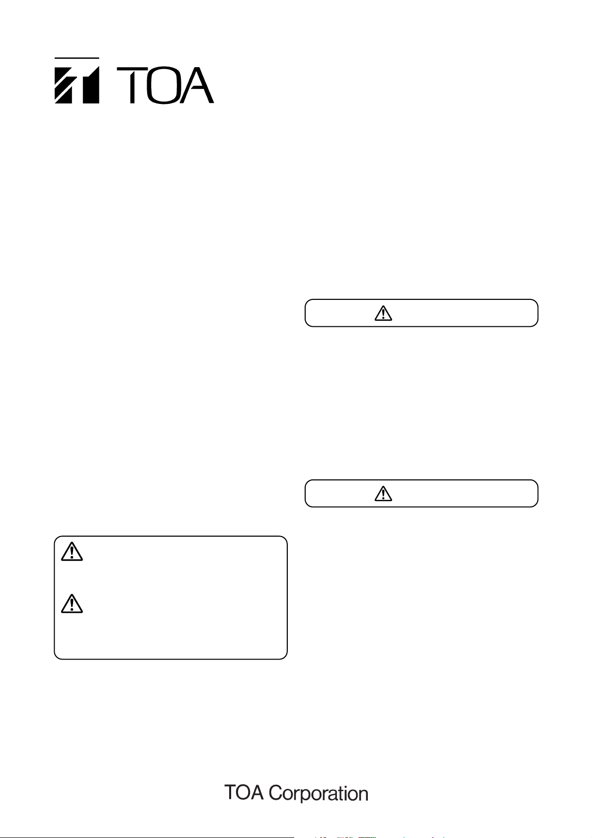
3. MOUNTING THE BRACKET
• Attach the supplied bracket to a heavy-duty wall, ceiling or room corner to withstand a load of the unit and
bracket.
• When only one of the two walls of the corner can be used, attach the bracket's larger plate (having four
mounting holes) to that wall.
Note: No mounting screws are supplied with the unit. Use screws suited to materials of the wall or ceiling.
[Bracket corner installation example for the
PS-16BM and PS-16WM]
[Bracket corner installation example for the
PS-32BM and PS-32WM]
(Unit: mm)
(Unit: mm)
Note: Be sure to secure the bracket firmly using four
screws or more.
4. CONNECTIONS
4.1. High Impedance (100 V Line) Connection
• One out of 1 kΩ (10 W), 2 kΩ (5 W), and 3.3 kΩ (3 W) input
terminals can be selected.
• Connect the selected terminal and COM terminal to an
amplifier.
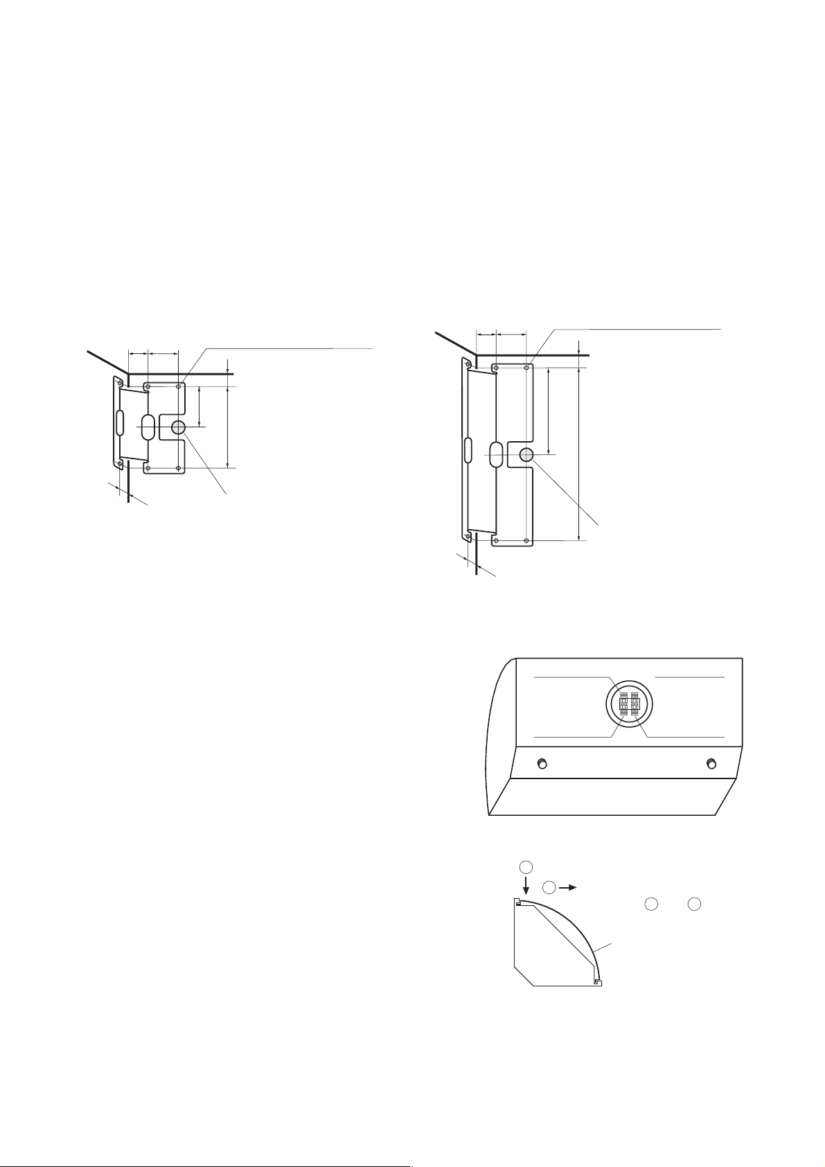
4.2. Low Impedance (8 Ω) Connection
Terminals are provided for high impedance operation when the
speaker system is supplied from the factory. When making low
impedance connections, change internal wiring by following
the procedures below:
1. Remove the punched grille (see the figure at right).
2. Remove the speaker element.
3. Disconnect cables (black and red) between the matching
transformer and speaker element at the speaker element.
Note
To prevent the terminals of the disconnected cables from contacting other terminals, wrap the insulation tape
round the terminals or cut them off from the disconnected cables.
Mounting holes with 5.5 mm dia.
303050
(6 places)
Over 20 mm
When this distance is 20 mm,
the speaker top panel
65
touches the ceiling surface.
130
Wiring hole
Mounting holes with 5.5 mm dia.
303050
(6 places)
Over 20 mm
When this distance is 20 mm,
the speaker top panel
145
touches the ceiling surface.
290
Wiring hole
3.3 kΩ (3 W)
2 kΩ (5 W)
COM
1 kΩ (10 W)
1
Push the punched grille in
2
the direction of the arrow
in order of and .
Punched grille
1 2
 Loading...