

Page 1
INSTRUCTION MANUAL
SOUND REPEATER PM-20EV
Please follow the instructions in this manual to obtain the optimum results from this unit.
We also recommend that you keep this manual handy for future reference.
1. SAFETY PRECAUTIONS ........................... 2
2. GENERAL DESCRIPTION ......................... 3
3. FEATURES ................................................. 3
4. HANDLING PRECAUTIONS ...................... 3
5. NOMENClATURE AND FUNCTIONS ........ 4
6. BROADCAST DELAY TIME
AND BUSY ON/OFF SETTINGS ................ 6
7. CHIME SETTINGS ...................................... 6
8. OPERATION ............................................... 7
9. CONNECTIONS ........................................ 10
10. USING THE SUPPLIED SOFTWARE ..... 12
11. SPECIFICATIONS .................................... 16
Accessories ............................................... 16
Optional products ...................................... 16
TABLE OF CONTENTS
Page 2
2
• Do not expose the unit to rain or an environment
where it may be splashed by water or other liquids,
as doing so may result in fire or electric shock.
• Use the unit only with the voltage specified on the
unit. Using a voltage higher than that which is
specified may result in fire or electric shock.
• Do not cut, kink, otherwise damage nor modify the
power supply cord. In addition, avoid using the
power cord in close proximity to heaters, and never
place heavy objects -- including the unit itself -- on
the power cord, as doing so may result in fire or
electric shock.
•
Avoid installing or mounting the unit in unstable
locations, such as on a rickety table or a slanted
surface. Doing so may result in the unit falling down
and causing personal injury and/or property damage.
• Should the following irregularity be found during
use, immediately switch off the power, disconnect
the power supply plug from the AC outlet and
contact your nearest TOA dealer. Make no further
attempt to operate the unit in this condition as this
may cause fire or electric shock.
· If you detect smoke or a strange smell coming
from the unit.
· If water or any metallic object gets into the unit
· If the unit falls, or the unit case breaks
· If the power supply cord is damaged (exposure of
the core, disconnection, etc.)
· If it is malfunctioning (no tone sounds.)
• Do not place cups, bowls, or other containers of
liquid or metallic objects on top of the unit. If they
accidentally spill into the unit, this may cause a fire
or electric shock.
• Do not touch the power supply plug during thunder
and lightning, as this may result in electric shock.
• Never plug in nor remove the power supply plug
with wet hands, as doing so may cause electric
shock.
• When unplugging the power supply cord, be sure
to grasp the power supply plug; never pull on the
cord itself. Operating the unit with a damaged
power supply cord may cause a fire or electric
shock.
• Avoid installing the unit in humid or dusty locations,
in locations exposed to the direct sunlight, near the
heaters, or in locations generating sooty smoke or
steam as doing otherwise may result in fire or
electric shock.
• Make sure that the volume control is set to
minimum position before power is switched on.
Loud noise produced at high volume when power is
switched on can impair hearing.
• Do not operate the unit for an extended period of
time with the sound distorting. This is an indication
of a malfunction, which in turn can cause heat to
generate and result in a fire.
• Use the AC adapter AD-246 (optional) or its
equivalent.
As for the usable adapter, consult your TOA dealer.
Note that the use of an adapter other than specified
may cause a fire.
• If dust accumulates on the power supply plug or in
the wall AC outlet, a fire may result. Clean it
periodically. In addition, insert the plug in the wall
outlet securely.
• Switch off the power, and unplug the power supply
plug from the AC outlet for safety purposes when
cleaning or leaving the unit unused for 10 days or
more. Doing otherwise may cause a fire or electric
shock.
CAUTION
1. SAFETY PRECAUTIONS
• Be sure to read the instructions in this section carefully before use.
• Make sure to observe the instructions in this manual as the conventions of safety symbols and messages
regarded as very important precautions are included.
• We also recommend you keep this instruction manual handy for future reference.
Safety Symbol and Message Conventions
Safety symbols and messages described below are used in this manual to prevent bodily injury and property
damage which could result from mishandling. Before operating your product, read this manual first and
understand the safety symbols and messages so you are thoroughly aware of the potential safety hazards.
Indicates a potentially hazardous situation which, if mishandled, could
result in death or serious personal injury.
Indicates a potentially hazardous situation which, if mishandled, could
result in moderate or minor personal injury, and/or property damage.
WARNING
CAUTION
WARNING
Page 3

3
2. GENERAL DESCRIPTION
The PM-20EV Sound Repeater is a paging microphone specially designed to record and play back the
broadcast contents.
It features a Rehearsal function that permits recorded message contents to be monitored before broadcast,
ensuring exacting announcement quality. Announcements can also be made directly from the PM-20EV's
built-in microphone, without requiring playback of prerecorded messages.
3. FEATURES
• Rehearsal function helps relieve tension and ensure accuracy during broadcasts.
• Built-in speaker permits recorded messages to be monitored before broadcast.
• Messages of up to 6 minutes in length can be recorded and played back with simple operation.
• Recorded data is not compressed, ensuring high quality sound output.
• A chime tone can be sounded before and after broadcasts.
• Internal chime data can be changed or messages recorded by connecting the unit to a personal computer
(PC) using the supplied USB cable.
• Built-in compression circuitry prevents sound output distortion caused by excessive signal input.
4. HANDLING PRECAUTIONS
• Warning: This is a class A products. In a domestic environment this product may cause radio interference
in which case the user may be required to take adequate measures.
• Note: This equipment has been tested and found to comply with the limits for a Class A digital device,
pursuant to Part 15 of the FCC Rules. These limits are designed to provide reasonable protection
against harmful interference when the equipment is operated in a commercial environment. This
equipment generates, uses, and can radiate radio frequency energy and, if not installed and used in
accordance with the instruction manual, may cause harmful interference to radio communications.
Operation of this equipment in a residential area is likely to cause harmful interference in which case
the user will be required to correct the interference at his own expense.
• To avoid radio interference, keep the unit and the optional AC adapter as far away as possible from radios or
wireless tuners.
• Do not open the case nor perform any modifications to the unit, as this may result in unit failure. Leave the
inspection, adjustment and repair of the unit's internal circuitry to your TOA dealer.
• The CD-ROM supplied with the unit is not for audio applications, and should not be used in an ordinary
audio CD player.
• Internal Copyright Acts prohibit the copy or use of commercially available music and sound data for
commercial purposes without the approval of the copyright holder. It is strongly advised that a copyright
lawyer be consulted when using such material.
• When cleaning the unit, be sure to switch off the unit's power first, then wipe with a dry cloth. Should the unit
become very dirty, use a cloth dampened in a neutral detergent. Never use benzene, thinner or chemicallytreated towels, as the unit's finish may be damaged.
Page 4
4
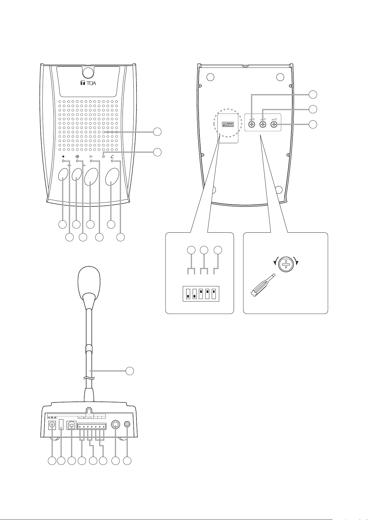
5. NOMENCLATURE AND FUNCTIONS
ENGINEERED IN JAPAN ASSEMBLED IN TAIWAN
TOA Corporation
SOUND REPEATER
N29
Tested to comply
with FCC standards
FOR HOME OR OFFICE USE
model PM-20EV
[Top]
1. Record Key [REC]
Records broadcast contents.
2. Recording Indicator
Flashes or continuously lights during recordings.
3. Monitor Key [MONITOR]
Permits monitoring of the recorded contents.
4. Monitor Indicator
Flashes or continuously lights during monitoring
of recorded contents.
5. Playback Key [PLAY]
Plays back recorded contents.
6. Playback Indicator
Flashes or continuously lights while recorded
contents are being broadcast.
[Top]
Sound Repeater
PM-20EV
REC
MONITOR
12345
PLAY
USB
TALK
7
9
10
[Bottom]
ON 54123
1: DELAY 2S
2: DELAY 4S
3: CHIME 1
4: CHIME 2
5: ALT/PTT
SOUND REPEATER
model PM-20EV
TOA Corporation
ENGINEERED IN JAPAN ASSEMBLED IN TAIWAN
FOR HOME OR OFFICE USE
with FCC standards
Tested to comply
11
12
CHIME MICSPEAKER
13
N29
[Rear]
DC IN 24V 200mA
USB
6
8
14 15 16
Adjusting controls
VOLUME LOW VOLUME HIGH
ON 54123
Use a screwdriver
to adjust.
25
LINE OUTBUSY
HCE
OUT
EXTLINE
MIC IN
17 18 19 20 21 22 23 24
Page 5

5
7. Talk Key [TALK]
Press this key to make announcements directly
from the microphone without broadcasting
recorded contents.
8. Talk Indicator
Flashes or continuously lights while the Talk key
(7) is held down for announcements.
9. Monitor Speaker
Used to monitor recorded contents.
10. USB Communication Indicator
Continuously lights or flashes during USB
communications.
[Bottom]
11. Speaker Volume Control [SPEAKER]
Adjusts the monitor speaker (9) volume.
12. Chime Volume Control [CHIME]
Adjusts the chime volume.
13. Microphone Volume Control [MIC]
Adjusts the microphone (25) volume.
14. Delay Time Setting DIP Switches [1, 2]
Set the delay time between broadcast activation
and actual start.
In addition, when time intervals between
repeated broadcasts are set with the supplied
software program, the busy output (21) during
the intervals can be selected for "Make" (ON) or
"Break" (OFF). Selecting "OFF" makes the delay
time 0 seconds. (Refer to p. 6.)
The delay time is factory-preset to 0 seconds,
and the busy output during intervals between
repeated broadcasts to "Make" (ON).
15. Chime Setting DIP Switches [3, 4]
Enables/disables pre- and post-announcement
chimes.
[3] (CHIME 1): Pre-announcement chime
[4] (CHIME 2): Post-announcement chime
Both switches are factory-preset to ON (to sound
chime tones before and after broadcasts).
Note
If the Chime setting switch is set to the OFF
position, chime tones are not recorded. However,
the chime tones do sound at the time of recording
to precisely indicate the timing of the recording.
16. Talk Key Mode Selector DIP Switch [5]
Determines the Talk key (7) operation mode.
The switch is factory-preset to ON (the microphone
turns on when the Talk key is pressed, and turns
off when pressed again).
[Rear]
17. AC Adapter Input Terminal [DC IN]
Connects to the optional AD-246 AC adapter or
its equivalent.
Tip: When this terminal and the DC Power Input
terminal (20) are simultaneously used, the
terminal receiving the higher voltage takes
precedence.
18. Cord Clamp
Wrap the AC adapter cord around this clamp to
prevent the plug from pulling out.
19. USB terminal
Connects to a PC or a USB hub using the supplied
USB cable.
20. DC Power Input Terminal [DC IN]
Connects to the 24 V DC power supply.
21. Busy Output Terminal [BUSY]
Closed during broadcast. When time intervals
between repeated broadcasts are set with the
supplied software program, the busy output
during the intervals can be selected for "Make"
(ON) or "Break" (OFF) by the Delay Time Setting
DIP switches (14).
Contact capacity: 30 V DC, 0.5 A
22. Line Output Terminal [LINE OUT]
Outputs the unit's playback contents.
(Refer to p. 11.)
0 dB, 600 Ω, balanced.
Note: Avoid simultaneously using this terminal
and the Line output jack (23).
23. Line Output Jack [LINE OUT]
Outputs the same contents as those of the Line
output terminal (22).
0 dB, 600 Ω, balanced, phone jack.
Note: Avoid simultaneously using this jack and
the Line output terminal (22).
24.
External Microphone Input Terminal [EXT MIC IN]
Connects to an optional WH-4000A headset
microphone. (Refer to p. 10.)
–37 dB, 2.2 kΩ, unbalanced, mini jack.
Note: To avoid unit failure, do not connect any
equipment other than the WH-4000A
microphone to this terminal.
25. Microphone
A preinstalled unidirectional gooseneck microphone
.
Cord clamp
AC adapter plug
Page 6

6
6. BROADCAST DELAY TIME AND BUSY ON/OFF SETTINGS
7. CHIME SETTINGS
The delay time between message activation and the actual start of playback can be set to 0, 2, or 4 seconds
with the unit's bottom-mounted Delay Time Setting DIP switches.
In addition, when time intervals between repeated broadcasts are set with the supplied software program, the
busy output during the intervals can be selected for "Make" (ON) or "Break" (OFF).
(Factory-preset to "0" seconds, and the busy output during intervals between repeated broadcasts to "ON.")
Should the beginning of playback contents be lost due to operational delays experienced by connected
external equipment, set the delay time to 2 or 4 seconds.
Note: If the delay time is set to 2 or 4 seconds, the Busy Output terminal is closed during the delay as well.
Tip: When shipped, the chimes are set to sound an ascending 4-note tone before broadcast and a
descending 4-note tone after broadcast. The chime tones can be changed using the data transfer
program found on the supplied CD-ROM. For more information, please refer to the "EV20 Software
Instruction Manual.pdf" file located on the CD-ROM.
The built-in chime can be set to sound (or not) before and after recorded message broadcasts and direct
microphone announcements using the unit's bottom-mounted Chime Setting DIP switches.
Note: The Chime switches are initially preset at the factory to sound chime tones before and after broadcasts
(both switches set to ON).
Delay Time Setting DIP Switches
Set Delay Time
0 seconds
(Factory-preset)
Delay Time Setting
DIP Switches
ON 1 2
Busy Output
during Time Intervals*
ON
(Make)
ON 54123
ON 1 2
1: DELAY 2S
2: DELAY 4S
3: CHIME 1
4: CHIME 2
5: ALT/PTT
2 seconds
ON 1 2
4 seconds
ON 1 2
0 seconds
Valid only when the time intervals between repeated broadcasts are set
*
with the supplied software program.
ON
ON
OFF
(Break)
Chime Setting DIP Switches
Preannouncement
Postannouncement
Pre-announcement:
Post-announcement:
CHIME
Sounded
Sounded
Chime Setting DIP Switches
ON 3 4
(Factory-preset)
ON 54123
1: DELAY 2S
2: DELAY 4S
3: CHIME 1
4: CHIME 2
5: ALT/PTT
Pre-announcement:
Post-announcement:
Pre-announcement:
Post-announcement:
Pre-announcement:
Post-announcement:
Sounded
Not sounded
Not sounded
Sounded
Not sounded
Not sounded
ON 3 4
ON 3 4
ON 3 4
Page 7

7
8. OPERATION
8.1. Recording (REC)
Messages are recorded on the internal flash memory.
The total recording time is approximately 6 minutes, including chime plays. Because the recording circuitry
features automatic gain control (AGC) function, the recording level does not need to be adjusted.
Note: Chime tones are not recorded if the Chime setting switch is set to the OFF position. However, the chime
tones will still sound during recordings in order to precisely indicate the timing of the recording.
Step 1. Press the Record key until the recording indicator begins to flash.
After indicator operation changes from flashing to steady ON, speak into the microphone to start
recording.
(The indicator begins to flash 1 second after the key is pressed. A chime tone sounds several
seconds after the indicator begins to flash, and the indicator switches from flashing to steady ON after
the chime sounds.)
Step 2. To stop the recording, press the corresponding Record key again.
Tips
• The Recording indicator begins flashing when only 5 seconds of recording time remain, and continues until
recording is complete.
• To delete the recorded contents, press the Record key, then press the Record key again while the recording
indicator is flashing.
• Sample chime tones contained in the supplied CD-ROM can be transferred to the PM-20EV for use. It is
also possible to back up the messages using the data transfer software program contained in the supplied
CD-ROM. For details, please read the "EV20 Software Instruction Manual.pdf" file located on the CD-ROM.
8.2. Monitoring Recorded Messages (MONITOR)
Step 1. Press the Monitor key.
The monitor indicator mode changes from flashing to steady ON, and the recorded message is played
back for monitoring.
Step 2. To stop monitor playback, press the corresponding Monitor key again.
Recorded contents can be easily monitored.
Recorded messages are heard through only the unit's monitor speaker during monitoring operation.
This playback is not delivered through the Busy output and Line output terminals.
[Top]
Sound Repeater
PM-20EV
Monitor Speaker
Monitor Indicator
Recording Indicator
Record Key
Monitor Key
REC
MONITOR
PLAY
USB
TALK
Playback Indicator
Talk Indicator
Talk Key
Playback Key
Page 8

8
8.3. Broadcasting Recorded Messages (PLAY)
Recorded messages for broadcast are output through the Line output terminal.
The Busy output terminal is closed during broadcast.
In addition, when time intervals between repeated broadcasts are set with the supplied software program, the
busy output during the intervals can be selected for "Make" (ON) or "Break" (OFF).
Step 1. Press the Playback key for 1 second or more.
The recorded message is broadcast when the indicator remains continuously lit.
When the message reaches its end, the broadcast is automatically terminated and the indicator is
extinguished.
Step 2. Press the Playback key again to stop broadcasts while in progress.
[Operating status of the PM-20EV after the Playback key is pressed]
[Operating status of the PM-20EV during repeat broadcasts]
Using the supplied software program, setting the "Interval" item to values other than "no repeat" permits
repeat broadcasts. The busy output during the repeat intervals can be selected for "Make" (ON) or "Break"
(OFF) by the Delay Time Setting DIP switches. When the "Interval" is set to "0 sec", the busy output remains
at "Make" during repeated broadcasts irrespective of the Delay Time Setting DIP switch settings.
1 second
or more
ON
Playback Key
1 second
Broadcast status
Playback indicator
status
1
Delay*
Flashing Steady-ON
Chime*
2
Broadcast
ON (Make)
Busy output
*1 Can be set to 0, 2 or 4 seconds using the Delay time setting switch.
*2 Time length changes depending on the set chime type.
Broadcast status
Broadcast Silence
Broadcast
• When the busy output
during repeat intervals is set to "Make" (ON)
Busy output
• When the busy output
during repeat intervals is set to "Break" (OFF)
Busy output
Repeat interval
Make (ON)
Make (ON)
Break (OFF)
Page 9

9
8.4. Making Announcements Directly from the Microphone (TALK)
Follow the procedure below to make announcements directly from the microphone using the Talk key, instead
of broadcasting recorded messages.
The Talk key's operations can be set using the Talk Key Mode Selector DIP switch located on the bottom of
the unit. (Factory-preset to ON.)
8.4.1. When the Talk key mode selector switch is set to ON (initial setting at the factory)
8.4.2. When the Talk key mode selector switch is set to OFF
Step 1. Hold down the Talk key until the indicator remains lit, then speak into the microphone.
Tip
Do not release the Talk key even if the indicator begins to flash.
When the chime is set to ON, the indicator flashes and a chime tone sounds 1 second after the Talk
key is pressed. After chime play completion, indicator operation changes from flashing to steady ON,
allowing the microphone announcement to be made.
Step 2. Release the Talk key and terminate the broadcast.
When the chime is set to ON, the indicator mode changes to flashing and a chime tone sounds.
Step 1. Hold down the Talk key until the indicator remains lit, then speak into the microphone.
Tip
When the chime is set to ON, the indicator flashes 1 second after the key is pressed and a chime tone
sounds. After chime play completion, indicator operation changes from flashing to steady ON,
allowing the microphone announcement to be made.
Step 2. Press the Talk key again to terminate the broadcast.
When the chime is set to ON, the indicator mode changes to flashing and a chime tone sounds.
Talk Key Mode
Selector DIP Switch
Talk Key Mode
Selector DIP Switch
ON 5
ON (Factory-preset)
Pressing the Talk key permits announcements to be
Setting Contents
made. (Because the microphone remains turned on,
ON 54123
the Talk key may be released.)
The announcement broadcast is terminated when
the Talk key is pressed again.
1: DELAY 2S
2: DELAY 4S
3: CHIME 1
4: CHIME 2
5: ALT/PTT
ON 5
OFF
Announcements can be made while the Talk key is
held down.
The announcement broadcast is terminated when
the Talk key is released.
Page 10

10
9. CONNECTIONS
9.1. Connection Example
9.2. External Microphone Connections
Note
When the AC adapter input terminal and the DC Power Input terminal are simultaneously used, the terminal
receiving the higher voltage takes precedence.
An optional WH-4000A headset microphone can be connected to the External microphone input terminal
located on the rear panel.
Notes
• Connecting the external microphone disables the unit's built-in
microphone.
• When using the WH-4000A headset microphone, position the
microphone set approximately 1 cm away from the mouth and
speak a bit louder. The WH-4000A microphone is fitted with a
plug lock, however a corresponding lock is not included with the
PM-20EV unit.
To AC mains, 50/60 Hz
(When operating unit on AC power supply)
[PM-20EV Rear]
Headset microphone
WH-4000A (optional)*
DC IN 24V 200mA
AD-246 AC adapter
(optional)
USB cable
PC
(supplied with unit)
24 V DC
power supply
(When operating unit on DC power supply)
USB
LINE OUTBUSY
HCE
EXTLINE
MIC IN
OUT
Unbalanced-phone plug cord
(supplied with unit)
*
To avoid unit failure,
do not connect any equipment
other than the WH-4000A
microphone to this terminal.
Power amplifier
Tip
The LINE OUT terminal on the terminal block outputs
the same signal as the LINE OUT phone jack.
It is recommended that the terminal block terminal be
used for permanent installation applications.
Remote control input of power amplifier, etc.
Plug lock
ø3.5 mm
Microphone
Page 11

11
9.3. Connections to the Rear-Mounted Connectors
Notes
• Use the appropriate type of screwdriver for the connector wiring screws.
• When using stranded or shielded cable, do not solder the stripped and exposed ends.
When the cable is clamped, the solder becomes crushed, increasing contact resistance and possibly
resulting in an extreme rise in cable joint temperature.
Conductor cross-sectional area 0.5 – 1.5 mm
2
AWG AWG24 – 16
9.3.1. Matching cable size
9.3.2. Stripped cable end
9.3.3. Cable connections
9.3.4. Line output terminal connections
Step 1. Loosen the terminal screw to insert the cable into
the connector, then retighten the screw.
Note
Tug lightly on the cable to be sure that it does not
pull free. If the cable pulls free, loosen the terminal
screw again and reconnect from the beginning.
Step 2. Insert the connector into the rear-mounted socket.
Notes
• Take care not to reverse Steps 1 and 2.
When tightening the terminal screw, force is applied to the connector pins on the internal circuit board,
possibly resulting in poor contact.
• Be sure all unused terminal screws are also tightened. Loose screws may produce rattling sounds in
response to monitor speaker vibration.
The Line output terminal is internally connected in parallel to the Line output jack. Do not use both terminals
simultaneously.
[Connection to a balanced amplifier] [Connection to an unbalanced amplifier]
Note
Short the E (ground) and C (cold) amplifier terminals
when using the Line output jack.
Solid and stranded cables
6 mm
Shielded cable
6 mm
15 mm
Terminal screw
Connector
(Accessory)
Tighten
1
Flat-blade screwdriver
Loosen
To unit's rear panelmounted socket
2
LINE OUT
CEH
LINE OUT
CE
H
To power amplifierTo power amplifier
Page 12

12
10. USING THE SUPPLIED SOFTWARE
The PM-20EV is equipped with a USB interface jack.
The following operations can be carried out by connecting a PC using the supplied USB cable:
• Uploading the chime tone contained in the supplied CD-ROM.
• Downloading recorded data to the PC. (Recorded data backup)
• Uploading data backed up in the PC.
For instructions regarding use of the supplied software, read the "EV20 Software Instruction Manual.pdf" file
located on the CD-ROM.
10.1. System Requirements
The following PC specifications are highly recommended for correct operation of the unit's software.
Notes
• Pentium is a trademark of Intel Corporation.
• Windows is a trademark of Microsoft Corporation.
Personal Computer IBM-AT compatible type (equipped with the USB terminal)
Main Specifications CPU: Pentium compatible CPU of 133 MHz or more
Memory: Over 64 MB (recommended: 128 MB or more)
Free disk space: Over 10 MB (space for message storage excluded)
OS Windows 2000/XP
10.2. CD-ROM File Configuration
The unit's supplied CD-ROM is configured as follows:
* Acrobat Reader is required to view this file. If Acrobat Reader is not installed in the PC to be
used, download it from the Adobe web site.
Note: Both Adobe and Acrobat are trademarks of Adobe Systems Incorporated.
CD-ROM
Driver
ReadmeENG.txt
English
Sample data
Sample data table.pdf*
EV20ENG.msi
EV20 Software
Instruction Manual.pdf*
Contains the USB driver necessary for USB connection of the
PM-20EV to a PC.
Contains the supplied software's system requirements and
update log data. Please read this before using the software.
Contains the following folders and files in English.
Contains sample chime tone data.
Shows the contents of sample data.
Use this when installing the data transfer software program.
Instructions for the data transfer software program.
Read this file after installing the software program.
ReadmeJPN.txt
Japanese
Japanese version of ReadmeENG.txt.
PCs require Japanese OS for correct operation.
Contains a software program, data, instruction manual, etc. of
Japanese version.
PCs require Japanese OS for correct operation.
Page 13

13
10.4.1. USB driver installation
Step 1. Start the PC.
Step 2. Insert the supplied CD-ROM into the PC's CD-ROM drive.
Step 3. Check to be sure that the unit's power is switched OFF.
Step 4. Using the supplied USB cable, connect the unit's front-mounted USB terminal to the USB terminal of
the PC or USB hub.
Step 5. Switch on the power to the unit.
The following screen is displayed on the PC screen.
A few seconds later, the following screen is displayed.
After another few seconds, the following screen is displayed.
When the PM-20EV is in the following operating states, do not switch off its power nor insert or remove the
USB cable. PC operation may stop.
• While the driver software program is being installed.
• While the OS is being activated or terminated.
• During the course of being suspended or resumed.
• While data is being transferred between the unit and the PC.
Because PC operations could also freeze, avoid performing the following:
• Frequent ON and OFF power switching
• Frequent USB cable insertion and detachment
To use the USB function, correctly install the software programs in the PC.
Two software programs need to be installed: The USB driver and data transfer software programs.
Note: Before operating, confirm the CD-ROM drive letter (such as E or F) of the PC to be used. The drive
letter is displayed near the CD-ROM icon in "My Computer."
10.4. Software Program Installation
10.3. Notes on Use of Software
Page 14

14
Cause
USB cable is not
correctly connected.
PC does not initiate
USB operation.
Unknown device
programmed.
[Troubleshooting when the driver cannot be installed]
Remedy
Unplug the USB cable, then reinsert it.
When connecting the PM-20EV to the PC, if the Step 5 screen for the USB
driver installation is not displayed, the PC may be set to disable USB. Check PC
settings with the following procedure:
Step 1. Select "My Computer" – "Control Panel" – "System."
Step 2. Click "Device Manager" in "Hardware."
Step 3. Check to be sure that there is no "!" or "X" symbol in "USB Controller"
and "USB Root Hub." When "!" or "X" symbols are displayed, perform
settings so that USB can be used. For the setting procedure, refer to PC
instruction manual.
When the driver cannot be correctly installed, the PM-20EV may be recognized
as an "Unknown Device," making installation impossible thereafter.
Delete "Unknown Device" with the following procedure:
Step 1. Select "My Computer" – "Control Panel" – "System."
Step 2. Click "Device Manager" in "Hardware."
Step 3. Click "Display" to select "Device (classified by type) (E)."
Step 4. Ensure there is no "Other Device."
Step 5. When there is "Other Device," click that tab. If there is "Unknown File"
under the tab, select and delete it.
Step 6. Remove the USB cable and after reinserting it, reinstall the driver.
Step 6. Select the source to copy.
Pull down "Copy files from:" to select "\Driver" in the CD drive.
Note: The drive letter may differ depending on the type of PC to be used.
Step 7. Click the OK button to start driver installation.
The screen disappears in several seconds and the driver installation is completed.
Page 15

15
10.4.2. Installing the data transfer software program
Step 1. Start the PC.
Step 2. Insert the supplied CD-ROM into the PC's CD-ROM drive.
Step 3. Double-click "CD-ROM Drive" from "My Computer" on the desktop screen.
Step 4. Select "English" folder and double-click "EV20ENG.msi."
The following screen is displayed on the PC screen.
Step 5. Click the Next button according to the instructions on the screen until the installation is completed.
The Data Transfer Program "EV20man.exe" file has been installed in the designated folder
(c:\ProgramFiles\EV-20PC\ by default).
Step 6. Click the Close button.
The screen disappears, completing the software program installation.
Ensure that the "EV20man.exe" file has been correctly installed.
Page 16

133-12-830-1B
• Accessories
• Optional products
AC adapter: AD-246
Headset microphone: WH-4000A
Note: When you need the AC adapter, be sure to consult your TOA dealer.
11. SPECIFICATIONS
Power Source Supplied from an external 24 V DC/200 mA power supply or
from an optional AD-246 AC adapter or its equivalent
Power Consumption 5 W (rated output)
Wave Format 44.1 kHz sampling frequency, 16-bit PCM (monaural)
Frequency Response 50 – 20,000 Hz ±3 dB (1 kHz)
Distortion Under 1% (1 kHz, rated output)
Recording System USB data transfer or analog recording
Control Output Busy: Contact capacity 30 V DC / 0.5 A, terminal block type connector
Input Unidirectional gooseneck microphone (preinstalled on the unit)
External microphone: –37 dB*, 2.2 kΩ, unbalanced, mini jack
Output Line output: 0 dB*, 600 Ω, balanced, phone jack
0 dB*, 600 Ω, balanced, terminal block type connector
Monitor speaker (built inside): 0.2 W
LED Indicator USB, REC, MONITOR, PLAY, TALK
Internal Chime Tone 2 tones: 4-tone chime (Up) and 4-tone chime (Down), ON/OFF operations
Maximum No. of Messages 1
Maximum Recording Time 6 minutes (including chime playback)
Message Delay Time 0, 2 s, or 4 s (selectable)
Playback Interval Time , 0, 5 s, 10 s, 30 s, 1 min, 5 min, 10 min, 30 min, or 1 h (selectable)
Finish Case: ABS resin, silver
Dimensions 122 (w) x 48.8 (h) x 180 (d) mm (microphone and projections not included)
Weight 710 g
* 0 dB = 1 V
Notes
• The design and specifications are subject to change without notice for improvement.
• Pentium is a trademark of Intel Corporation.
• Windows is a trademark of Microsoft Corporation.
• Regarding other company names and products, they are also trademarks of individual companies.
[USB Data Transfer Software Operation Environment]
Personal Computer IBM-AT compatible type (equipped with the USB terminal)
Main Specifications CPU: Pentium compatible CPU of 133 MHz or more
Memory: Over 64 MB (recommended: 128 MB or more)
Free disk space: Over 10 MB (space for message storage excluded)
OS Windows 2000/XP
CD-ROM (USB data transfer software
and sample chime tones recorded) ..... 1
USB cable (1 m) .................................................... 1
Unbalanced-phone plug cord (2 m) ....................... 1
Terminal block type connector (7 poles) ............... 1
 Loading...