

Page 1
1. SAFETY PRECAUTIONS
• Before installation or use, be sure to carefully read all
the instructions in this section for correct and safe
operation.
• Be sure to follow all the precautionary instructions in
this section, which contain important warnings and/or
cautions regarding safety.
• After reading, keep this manual handy for future
reference.
• Install the unit only in a location that can structurally
support the weight of the unit and the mounting bracket.
Doing otherwise may result in the unit falling down and
causing personal injury and/or property damage.
• Do not use other methods than specified to mount the
bracket. Extreme force is applied to the unit and the unit
could fall off, possibly resulting in personal injuries.
• Tighten all screws securely. If any is loosely fixed, this
may cause the unit to fall, resulting in personal injury.
• To avoid electric shocks, be sure to switch off the
amplifier's power when connecting speakers.
• Do not operate the unit for an extended period of time
with the sound distorting. This is an indication of a
malfunction, which in turn can cause heat to generate
and result in a fire.
• Do not hang down from the unit as this may cause it to
fall down or drop, resulting in personal injury and/or
property damage.
The PE-64 and PE-304 are pendant speakers designed
for ceiling suspension installations.
Considered in architectural design, they can blend in with
lighting equipment.
A directly-attached 5 m (16.4 ft) speaker cord allows the
speaker to be suspended from the high ceiling.
The PE-64 is driven on high-impedance (100 V and 70 V)
line, while the PE-304 is driven on both high-impedance
(100 V and 70 V) and low-impedance (8 Ω) lines.
The input power (impedance) can be easily changed at
the upper side of the speaker.
The speakers are easy to repaint so as to meet a wide
range of design needs.
2. GENERAL DESCRIPTION
Note: The design and specifications are subject to change without notice for improvement.
3. SPECIFICATIONS
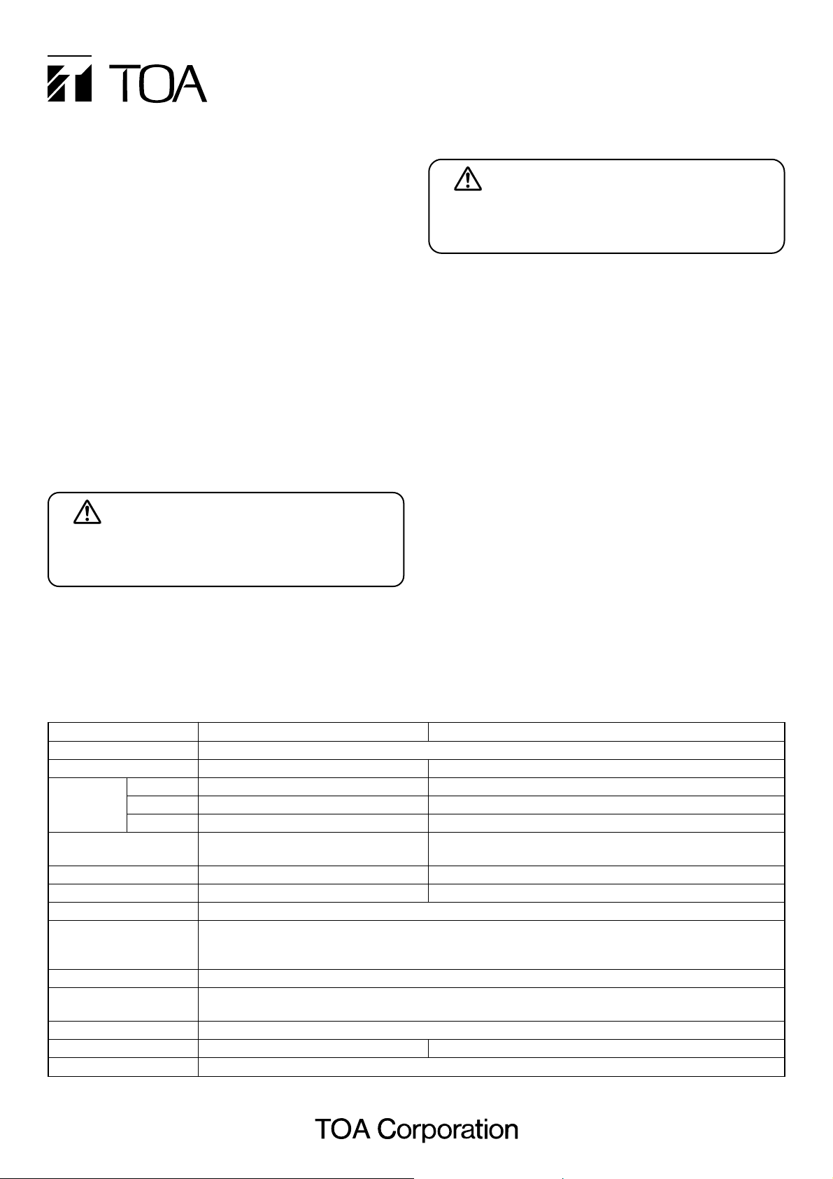
PE-64 PE-304
Bass-reflex type
6 W (100 V line), 3 W (70 V line) 30 W (100 V, 70 V line, 8 Ω)
–
8 Ω
1.7 kΩ (6 W), 3.3 kΩ (3 W), 10 kΩ (1 W) 330 Ω (30 W), 500 Ω (20 W), 670 Ω (15 W), 1 kΩ (10 W), 2 kΩ (5 W)
1.7 kΩ (3 W), 3.3 kΩ (1.5 W), 10 kΩ (0.5 W) 170 Ω (30 W), 250 Ω (20 W), 330 Ω (15 W), 500 Ω (10 W), 1 kΩ (5 W)
90 dB (1 W, 1 m) 91 dB (1 W, 1 m)
100 – 18,000 Hz (at 20 dB below peak) 70 – 20,000 Hz (at 20 dB below peak)
12 cm (5") cone type 12 cm (5") cone type + balanced dome-tweeter
2-core cabtyre cord 5 m (16.4 ft)
600 V vinyl-insulated cable (IV wire or HIV wire)
Solid wire: ø0.8 – ø1.6 mm (equivalent to AWG 20 – 14)
7-core twisted wire: 0.75 – 1.25 mm2(equivalent to AWG 18 – 16)
Push-in connector (bridging terminal of 2 branch type)
Enclosure: HIPS resin, off white (RAL 9010 or equivalent color)
Grille: Surface-treated steel plate net, off white (RAL 9010 or equivalent color), paint
ø186 x 251 (h) mm (ø7.32" x 9.88")
1.5 kg (3.31 lb) 2.1 kg (4.63 lb)
Ceiling bracket ...... 1, Mounting hanger ...... 1, Ceiling cover ...... 1, Tapping screw 4 x 16 ...... 4
Model No.
Enclosure
Rated Input
Rated
Low
Impedance
100 V line
70 V line
Sensitivity
(500 – 5,000 Hz, pink noise)
Frequency Response
Speaker Component
Speaker Cord
Application Cable
Connection
Finish
Dimensions (unit only)
Weight (unit only)
Accessories
INSTALLATION MANUAL
PENDANT SPEAKERS
PE-64
PE-304
Thank you for purchasing TOA's Pendant Speakers.
Please carefully follow the instructions in this manual to
ensure long, trouble-free use of your equipment.
WARNING
Indicates a potentially hazardous situation which, if
mishandled, could result in death or serious
personal injury.
CAUTION
Indicates a potentially hazardous situation which, if
mishandled, could result in moderate or minor
personal injury, and/or property damage.
Page 2
6. INSTALLATION
Step 1. Secure the ceiling bracket to the ceiling
with 4 screws.
Pull both the lead-in and lead-out cables
through the cable hole in the bracket.
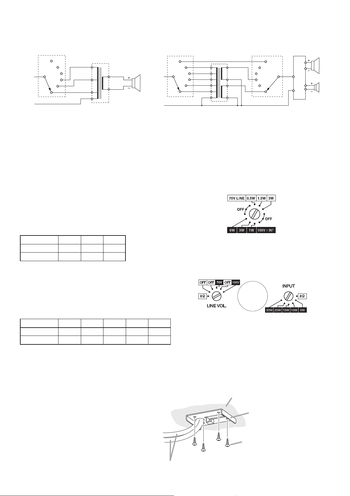
The input power (impedance) is factory-preset to 6 W
(1.7 kΩ) for 100 V line and 3 W (1.7 kΩ) for 70 V line.
When changing this setting, use a standard screwdriver
to rotate the rotary switch on the upper side of the
speaker to the desired position
The input power (impedance) is factory-preset to 30 W
(330 Ω) for 100 V line.
When changing this setting, use a standard screwdriver
to rotate the rotary switches on the upper side of the
speaker to the desired position.
(1) When operating at high impedance (100 V and 70 V lines);
Set the rotary switch of "LINE VOL." to "100 V" or "70 V" and that of "INPUT" to the input power to be used.
(2) When operating at low impedance;
Set both rotary switches of "LINE VOL" and "INPUT" to 8 Ω.
Important
Be sure to follow the instructions below. Failure to do so may cause damage to the speaker.
• Switch off the amplifier's power when changing the input power.
• Never make 8 Ω connection in a 100 V or 70 V line system, as excessive input power is applied to the speaker,
possibly resulting in damage. (PE-304 only)
5. INPUT POWER (IMPEDANCE) CHANGE
5.2. PE-304
5.1. PE-64
Impedance 1.7 kΩ 3.3 kΩ 10 kΩ
100 V line 6 W 3 W 1 W
70 V line 3 W 1.5 W 0.5 W
Input power 30 W 20 W 15 W 10 W 5 W
100 V line 330 Ω 500 Ω 670 Ω 1 kΩ 2 kΩ
70 V line 170 Ω 250 Ω 330 Ω 500 Ω 1 kΩ
4. WIRING DIAGRAMS
4.1. PE-64
4.2. PE-304
Rotary switch
OFF
HOT
COM
OFF
OFF
Matching
transformer
10 kΩ
3.3 kΩ
1.7 kΩ
COM
(Factory-preset wiring)
8 Ω
0
Rotary switch 1
8 Ω
HOT
COM
2 kΩ
1 kΩ
670 Ω
500 Ω
330 Ω
COM
Matching
transformer
16 Ω
0
8 Ω
0
Rotary switch 2
8 Ω
OFF
OFF
70 V
OFF
100 V
SP1
8 Ω
0
Network
(Factory-preset wiring)
SP2
Note
Shown above is an example when the input power is
set to 3 W on 100 V line and 1.5 W on 70 V line.
Note
Shown above is an example when the input power is
set to 20 W on 100 V line.
Ceiling
Lead-in and lead-out cables
Ceiling bracket (accessory)
Tapping screw 4 x 16 (accessory)
Note
If these screws are not appropriate
for the ceiling material, separately
prepare the proper screws.
Page 3
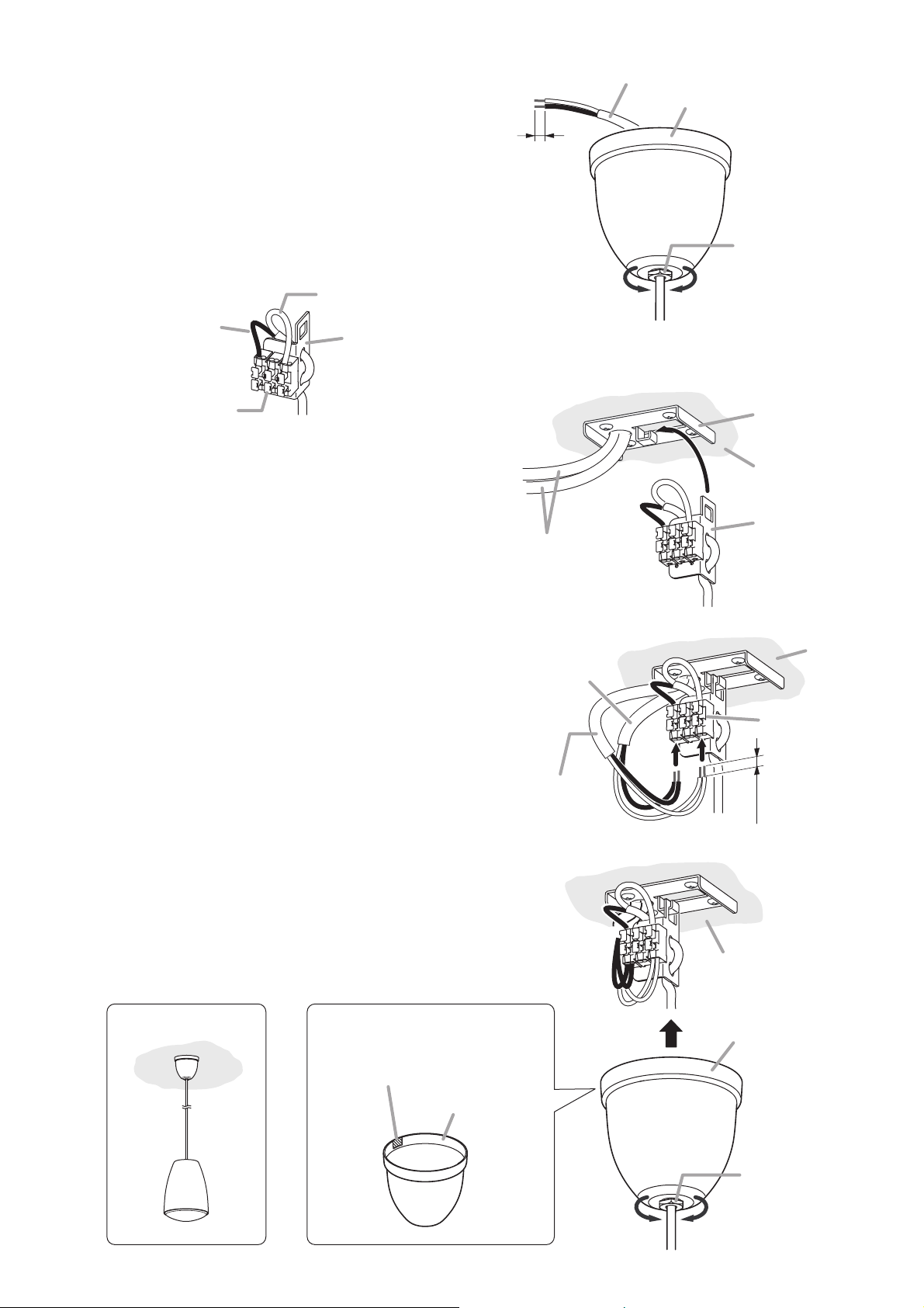
Step 2. Pass the speaker cord through the supplied ceiling
cover, and cut the cord to the desired length.
Note: Strip the end of speaker cord as illustrated.
Step 3. Run the speaker's cable through the cable holes in the
mounting hanger, then connect it to the input
connector.
Step 4. Put the mounting hanger onto the ceiling bracket's
hook.
Step 5. Connect both the lead-in and lead-out cables to the
input connector.
[Applicable cable]
• Solid wire: ø0.8 – ø1.6 mm
(equivalent to AWG 20 – 14)
• Stranded wire (7-core): 0.75 – 1.25 mm
2
(equivalent to AWG 18 – 16)
Step 6. Push the ceiling cover, slipped over the cord in Step 2,
onto the ceiling surface, then tighten the cover-retaining
nut using a 17 mm (0.67") hex wrench.
In the case of exposed wiring, notch the cable entry tab
on the rim of the cover, then make connections.
Speaker cord 5 m (16.4 ft)
Ceiling cover (accessory)
9 mm
(0.35")
COM (white)
HOT (black)
Input connector
Mounting hanger
(accessory)
Lead-in and
lead-out cables
From the
amplifier
Cover-retaining nut
TightensLoosens
Ceiling bracket
(accessory)
Ceiling
Mounting hanger
(accessory)
Ceiling
In the case of exposed wiringInstallation view
Notch this thin tab.
(another tab is on the opposite side.)
Ceiling cover
To the next
speaker
Input connector
9 mm
(0.35”)
Ceiling
Ceiling cover
Cover-retaining nut
TightensLoosens
Page 4
533-06-154-3A
URL: http://www.toa.jp/
7. REPAINTING THE SPEAKER
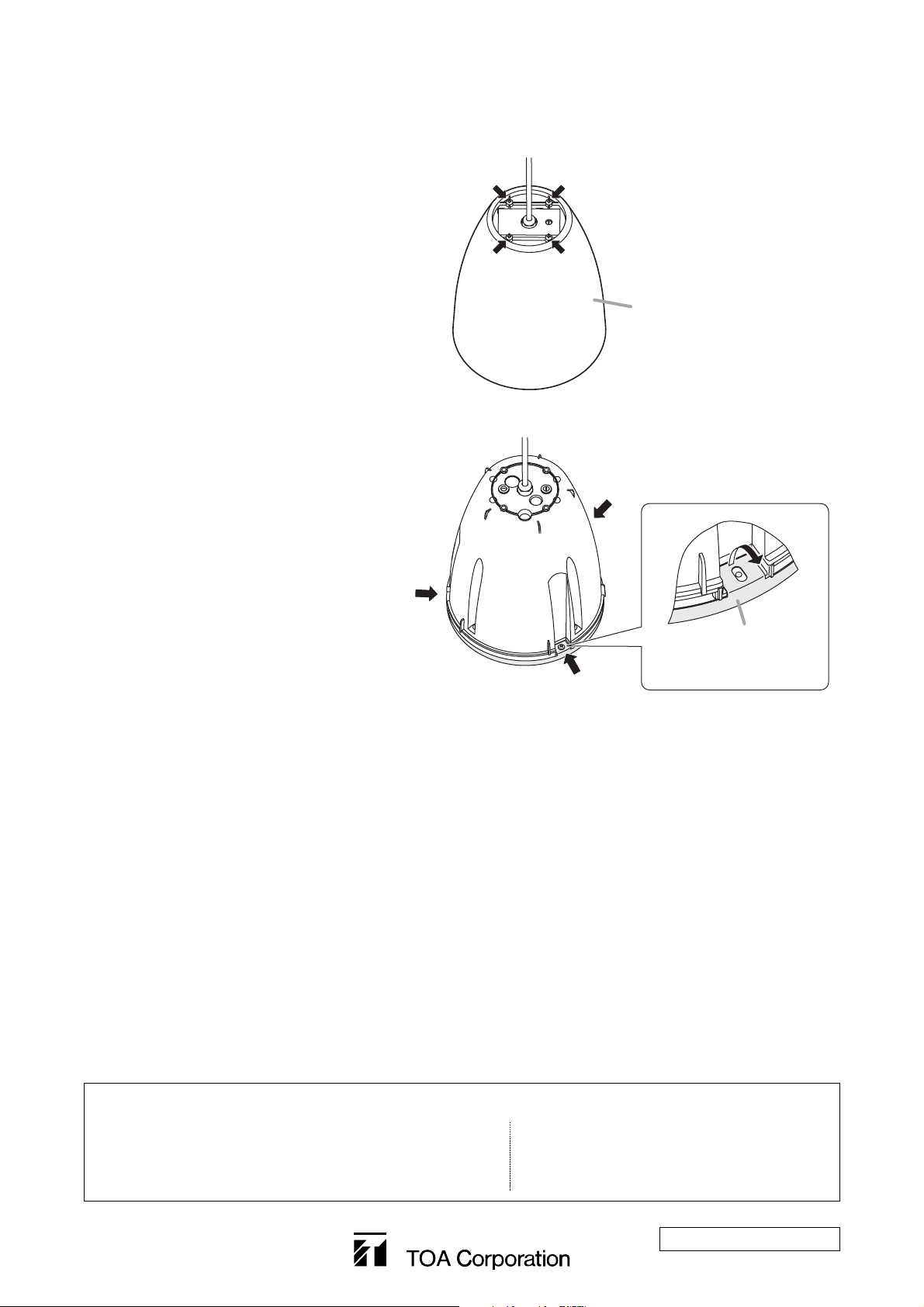
Step 1. Remove 4 screws on the upper side of the
speaker cover to detach the cover.
Step 2. Remove 3 screws that fix the mesh net,
then raise the turndown tabs of the mesh
net to detach.
Step 3. Clean the speaker cover and mesh net.
Wipe with a soft cloth damped in a detergent.
Note
Do not use thinner or other volatile liquids to clean them as doing so may cause deformation.
Step 4. Use spray paint to apply uniform and thin coat of paint.
Notes
• Avoid painting with a roller or brush, as the mesh net could become clogged with paint.
• Use appropriate paints for the speaker cover and mesh net materials.
· Speaker cover: Fire-resistant HIPS resin
· Mesh net: Rolled steel plate (acrylic paint)
Step 5. After the paint has dried, apply another light coat.
Repeating Step 4, apply 2 or more light coats of paint. Application of one thick coat of paint all at once
may cause drips or unevenness to show up in the painted finish, or clog the mesh holes.
Step 6. After the paint has dried, replace the speaker cover and mesh net.
Follow the procedure below when repainting the speaker cover and mesh net.
Note: Never touch the inner speaker diaphragm during work.
Traceability Information for Europe (EMC directive 2004/108/EC)
Manufacturer:
TOA Corporation
7-2-1, Minatojima Nakamachi, Chuo-ku, Kobe, Hyogo,
Japan
Authorized representative:
TOA Electronics Europe GmbH
Suederstrasse 282, 20537 Hamburg,
Germany
Remove 4 screws indicated by arrows.
Remove 3 screws indicated by arrows.
Speaker cover
Mesh net
Raise the turndown tab.
 Loading...