

Page 1
OPERATING INSTRUCTIONS
Note: The design and specifications are subject to change without notice for improvement.
Thank you for purchasing TOA's Wall Flush-Mount Speaker.
Please carefully follow the instructions in this manual to ensure long, trouble-free use of your equipment.
PC-391, PC-391T
WALL FLUSH-MOUNT SPEAKERS
1. SAFETY PRECAUTIONS
• Before installation or use, be sure to carefully read all the instructions in this section for correct and safe
operation.
• Be sure to follow all the precautionary instructions in this section, which contain important warnings and/or
cautions regarding safety.
• After reading, keep this manual handy for future reference.
WARNING
Indicates a potentially hazardous situation which,
if mishandled, could result in death or serious
personal injury.
CAUTION
Indicates a potentially hazardous situation which,
if mishandled, could result in moderate or minor
personal injury, and/or property damage.
• Install the unit only in a location that can
structurally support the weight of the unit and the
mounting bracket. Doing otherwise may result in
the unit falling down and causing personal injury
and/or property damage.
• Tighten each screw securely. Ensure that the
bracket has no loose joints after installation to
prevent accidents that could result in personal
injury.
• Use the specified electrical box in combination.
Doing otherwise may cause the unit or component
to fall off, resulting in personal injury.
• Avoid touching the unit's sharp metal edge to
prevent injury.
• Do not operate the unit for an extended period of
time with the sound distorting. This is an indication
of a malfunction, which in turn can cause heat to
generate and result in a fire.
2. GENERAL DESCRIPTION
The PC-391 and PC-391T are flush-mount speakers. Their ideal applications include hotel and hospital
rooms, and reception counters in the banks and clinics.
3. SPECIFICATIONS
Model Number PC-391 PC-391T
Rated Input 3 W
Rated Impedance 3.3 kΩ (3 W), 10 kΩ (1 W) 3.3 kΩ
Sound Pressure Level 86 dB (1 W, 1 m)
Frequency Response 150 Hz – 18 kHz
Speaker Component 7.7 cm cone-type speaker
Attenuation 0 (OFF), 1 (–12 dB), 2 (–6 dB), 3 (0 dB)
Applicable box YC-150/150E (option) or equivalent
Finish Aluminum, hair line
Dimensions 162 (w) x 115 (h) x 43 (d) mm 162 (w) x 115 (h) x 47 (d) mm
(excluding the projected screw heads) (
excluding the projected switch knob and screw heads)
Weight 560 g 600 g
Accessory Machine screw M4 x 35 ..... 4, Oval head countersunk screw M3 x 10 ..... 4, Tapping screw 4 x 16 ..... 4
Traceability Information for Europe
Manufacturer:
TOA Corporation
7-2-1, Minatojima-Nakamachi, Chuo-ku, Kobe, Hyogo, Japan
Authorized representative:
TOA Electronics Europe GmbH
Suederstrasse 282, 20537 Hamburg, Germany
Page 2
4. INSTALLATION
WARNING
When using an electrical box, be sure to use the
optional YC-150, YC-150E or equivalent.
Doing otherwise may cause the unit or
component to fall off, resulting in personal injury.
Note
Ensure that the electrical box mounting surface is
recessed 3 – 30 mm from the wall surface.
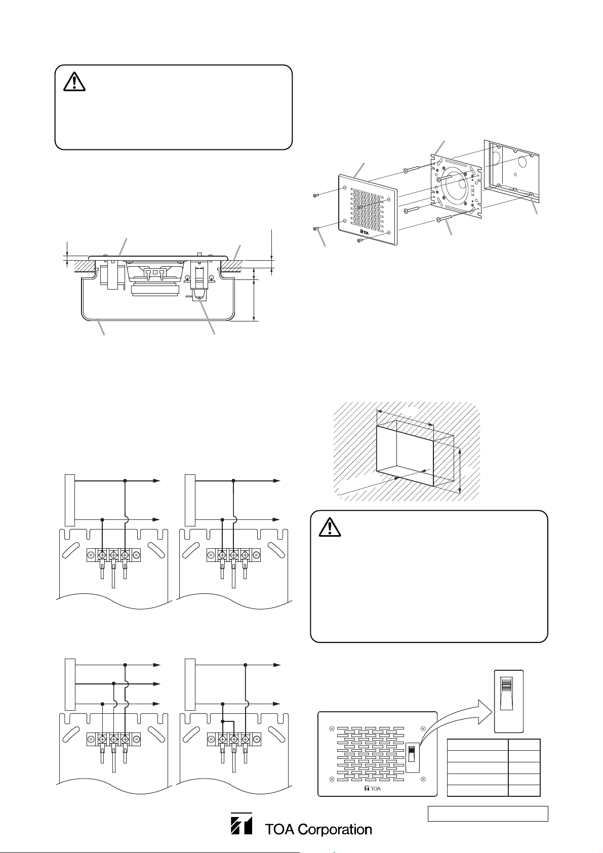
[View with the speaker installed in a wall]
Unit: mm
Note: Figure shows the PC-391T.
Step 1. Route the cables from the electrical box and
connect them to the screw terminal block on
the speaker unit.
Step 2. Mount the speaker unit to the electrical box
using the 4 supplied screws M4 x 35.
Step 3. Attach the speaker panel to the speaker unit
using the 4 supplied screws M3 x 10.
Note: Figure shows
the PC-391.
140
82
50 or
more
Unit: mm
WARNING
To tightly hold the tapping screws in place, the
wall material should be of strength equivalent to
that of 5 mm or more thick plywood. Ensure in
advance that the installation location can
structurally support the weight of the speaker.
Doing otherwise may result in the unit falling
down and causing personal injury and/or property
damage.
5. VOLUME CONTROL (PC-391T only)
Adjust the sound volume using the
slide switch on the speaker panel.
[Wiring diagram for the
PC-391 (1 W)]
[Wiring diagram for the
PC-391 (3 W)]
[Wiring diagram for the
PC-391T (3-wire system)]
[Wiring diagram for the
PC-391T (2-wire system)]
* When using an electrical box other than
our YC-150 or YC-150E, use screws that
are appropriate for that electrical box.
Note
The PC-391 or PC-391T can be flush mounted to the
wall without using an electrical box. In this case,
make a mounting hole in the wall as shown below.
When installing the speaker to a wooden wall, use
the supplied tapping screws.
133-01-444-0C
URL: http://www.toa.jp/
Speaker panel
Speaker unit
Speaker panel
5
Electrical box
(YC-150/150E or equivalent)
Wall surface
3 – 30
44 13
(Distance from wall surface)
Screw terminal block
Hot
Hot
Electrical box
Machine screw M4 x 35*
Oval head countersunk
screw M3 x 10 (accessory)
(accessory)
2
3
Common
Power amplifier
White
Black
Normal
Emergency
Common
Power amplifier
White
Red
Brown
Speaker unit
Black
Speaker unit
Common
To other speaker
Power amplifier
White
Black
Brown
Speaker unit
Hot
Common
Power amplifier
To other speaker
White
Red
Black
Speaker unit
To other speaker
To other speaker
PC-391T
Position of Switch
VOLUME
CONTROL
3
2
1
0
3
2
1
0
VOLUME
CONTROL
Volume
3 0 dB
2
1
0 OFF
-
-
12 dB
6 dB
 Loading...