

Page 1
CEILING MOUNT SPEAKERS PC-1869EN
PC-2369EN
Thank you for purchasing TOA's Ceiling Mount Speaker.
Please carefully follow the instructions in this manual to ensure long, trouble-free use of your equipment.
Traceability Information for Europe (EMC directive 2004/108/EC)
Manufacturer:
TOA Corporation
7-2-1, Minatojima Nakamachi, Chuo-ku, Kobe, Hyogo,
Japan
Authorized representative:
TOA Electronics Europe GmbH
Suederstrasse 282, 20537 Hamburg,
Germany
INSTRUCTION MANUAL
1. SAFETY PRECAUTIONS ........................... 1
2. GENERAL DESCRIPTION
AND FEATURES ......................................... 2
3. INSTALLATION .......................................... 3
4. WIRING DIAGRAM ..................................... 4
5. FREQUENCY RESPONSE ......................... 4
6. SPECIFICATIONS ...................................... 5
TABLE OF CONTENTS
1. SAFETY PRECAUTIONS
• Before installation or use, be sure to carefully read all the instructions in this section for correct and safe
operation.
• Be sure to follow all the precautionary instructions in this section, which contain important warnings and/or
cautions regarding safety.
• After reading, keep this manual handy for future reference.
When Installing the Unit
• Refer all installation work to the dealer from whom
the speaker was purchased. Installation work
requires extensive technical knowledge and
experience. The speaker may fall off if incorrectly
installed, resulting in possible personal injury.
• Install the speaker only in a location that can
structurally support the full weight of the unit and
mounting bracket. Doing otherwise may result in
the speaker falling down and causing personal
injury and/or property damage.
• Since the unit is designed for in-door use, do not
install it outdoors. If installed outdoors, the aging of
parts causes the unit to fall off, resulting in personal
injury. Also, when it gets wet with rain, there is a
danger of electric shock.
• Do not use other methods than specified to install
the speaker. Extreme force is applied to the
speaker and the speaker could fall off, possibly
resulting in personal injuries.
• Use screws that are appropriate for the ceiling's
material and structure. Failure to do so may cause
the speaker to fall, resulting in material damage
and possible personal injury.
• Ensure that all screws are securely tightened. If
they are loose after installation, the speaker could
fall down, possibly resulting in personal injury.
• Do not mount the speaker in locations exposed to
constant vibration. The speaker or its mounts can
Indicates a potentially hazardous situation which,
if mishandled, could result in death or serious
personal injury.
WARNING
Page 2

2
2. GENERAL DESCRIPTION AND FEATURES
The PC-1869EN and PC-2369EN are certified according to the European Standard EN 54-24: 2008 and the
International Standard ISO 7240-24: 2010.
Integrated with a speaker unit and panel, the PC-1869EN and PC-2369EN Ceiling Mount Speakers are of
metallic construction and ideal for use in a voice alarm system. They feature spring catch mechanism for easy
speaker mounting to the ceiling. The input impedance can be easily changed by changing the tap position of
the transformer. The screw terminal (steatite) makes input cable connections easy and allows bridge wiring.
Indicates a potentially hazardous situation which,
if mishandled, could result in moderate or minor
personal injury, and/or property damage.
CAUTION
be damaged by excessive vibration, potentially
causing the speaker to fall, which could result in
personal injury.
• Do not use anti-rust lubricant. If it contacts resin or
rubber parts, they could deteriorate and cause the
speaker to fall, possibly resulting in personal injury.
• Do not install the speaker in indoor swimming pools
or such locations where liquid chemicals are used.
The parts deteriorate if corroded, causing the
speaker to fall, which could result in personal
injury.
When the Unit is in Use
• If any of the following irregularities occurs,
immediately switch off the amplifier's power, and
inform the shop from where the speaker was
purchased. Further using the speaker may result in
fire or electric shock.
· If you detect smoke or a strange smell coming
from the speaker
· If water or any metallic object gets into the
speaker
· If the speaker falls, or the speaker case breaks
• To prevent a fire or electric shock, never open nor
remove the speaker case. Refer all servicing to
your nearest TOA dealer.
When Installing the Unit
• Avoid touching the speaker's sharp metal edge to
prevent injury.
• To avoid electric shocks, be sure to switch off the
amplifier's power when connecting speakers.
When the Unit is in Use
• Do not operate the speaker for an extended period
of time with the sound distorting. Doing so may
cause the speaker to heat, resulting in a fire.
• Do not stand or sit on, nor hang down from the
speaker as this may cause it to fall down or drop,
resulting in personal injury and/or property
damage.
• Have the speaker checked periodically by the shop
from where it was purchased. Failure to do so may
result in corrosion or damage to the speaker or the
mounts that could cause it to fall, possibly causing
personal injury.
Page 3
3
3. INSTALLATION
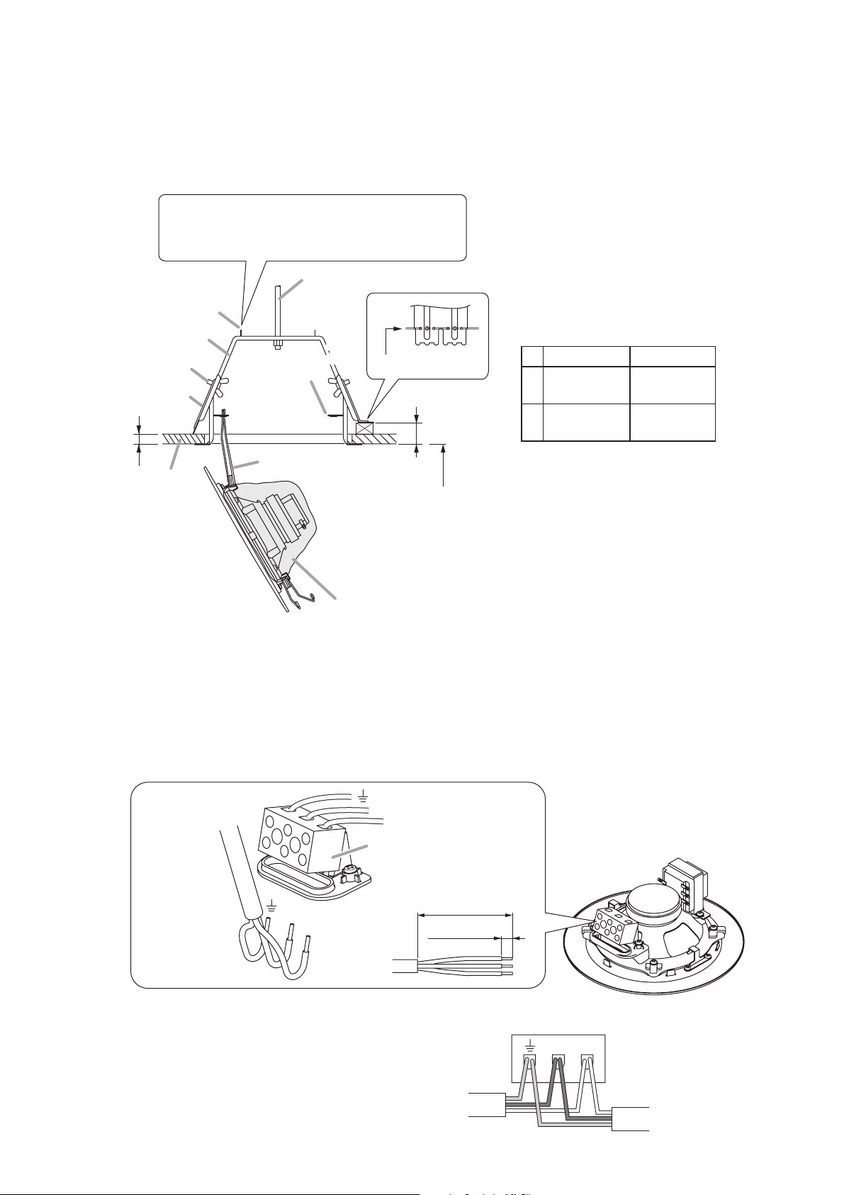
Step 1. Make a hole in the ceiling.
In the case of the PC-2369EN, marking-off pins provided on the mounting bracket will help draw the
circle of its diameter on the ceiling.
• PC-1869EN: 150 ±3 mm (5.91 ±0.12") diameter
• PC-2369EN: 200 ±3 mm (7.87 ±0.12") diameter
Step 2. Place the mounting bracket in the hole and secure it with the thumb screws in the 2 ceiling clamps.
Note: A suspension bolt may be used instead for fixing the mounting bracket (PC-2369EN only.)
Step 3. Hook one speaker spring (V-shaped spring) in the spring catcher of the bracket.
Step 4. Make wiring.
4-1. Connect the lead-in cable (the one from the amplifier) to the screw terminal. In this case, bend the
cables as shown below to facilitate the cable insertion into the input terminals.
When connecting the lead-out
cable (the one to the next speaker),
connect both the lead-in and leadout cables of the same polarity to
each corresponding input terminal.
Note*
Raise both pins, and draw a circle with the sharp
pin as its center and another pin as a scriber.
* PC-2369EN only
1
Suspension bolt*
Marking-off pin*
Mounting bracket
Thumb screw
Ceiling clamp
t2
Ceiling
Spring catcher
3
Speaker spring
2
Bent position
Splash proof cover
t1
2.5 m (8.2 ft
from the floor
Allowable board thickness for t1 and t2
PC-1869EN PC-2369EN
Max. 50 mm
(1.97")
Max. 34 mm
(1.34")
) or higher
Max. 30 mm
t1
(1.18")
Max. 15 mm
t2
(0.59")
From the speaker
unit (pre-wired)
COM
[Cable end treatment]
70 mm (2.76")
8 mm (0.31")
Viewed from the screw terminal's bottom side
COMHOT
From the amplifier
HOT
COM
HOT
Screw terminal
From the amplifier
To the next speaker
Page 4

4. WIRING DIAGRAM
4
4-2. Change the input impedance as needed. The
speaker's input is factory-preset to 1.7 kΩ. When
changing the input impedance, detach the black
wire connected to the matching transformer, and
reinsert it into the desired input tap referring to
the table at right.
Step 5. Mount the splash proof cover.
Important
Hook the splash proof cover at every points
marked with arrows in the figure at right. The
splash proof cover is compliant with the
dust/water protection rating IP21C.
Check that the cover is securely fixed to all
hooking positions to protect the speaker unit,
transformer, and connection terminal from water
splash.
(1) Hook the splash proof cover to the cover hook.
(2) Hook the splash proof cover under the Matching
transformer.
(3) Hook the splash proof cover under the terminal
mount.
(X) Do not remove the splash proof cover from these
positions.
Step 6. Hook another speaker spring in another catcher.
Then, press the speaker assembly into the
mounting bracket. Force of the springs will keep
the speaker in place.
5. FREQUENCY RESPONSE (1 W, 4 m)
5.1. PC-1869EN
Impedance 1.7 kΩ 3.3 kΩ 6.7 kΩ 13 kΩ
100 V line 6 W 3 W 1.5 W 0.8 W
70 V line 3 W 1.5 W 0.8 W 0.4 W
Bold figures represent factory-preset values.
5.2. PC-2369EN
Matching transformer
13kΩ
6.7kΩ
1.7kΩ
3.3kΩ
COM
HOT (black)
(1)
(X)
(1)
COM (white)
(2)
(1)
(X)
Thermal fuse
Screw terminal
Earth
HOT (+)
COM (–)
HOT (black)
COM (white)
(84 ºC or 183.2 ºF)
[dB]
90
(3)
Terminal mount
13 kΩ
6.7 kΩ
3.3 kΩ
*
1.7 kΩ
COM
* Factory-preset
(1)
Cover hook
Matching
transformer
8 Ω
0
80
70
60
[dB]
90
80
70
60
20 100 50050 1 k 5 k
Frequency-SPL
20 100 50050 1 k 5 k
Frequency-SPL
10 k 20 k [Hz]
10 k 20 k [Hz]
Page 5

5
6. SPECIFICATIONS
Notes
• The design and specifications are subject to change without notice for improvement.
• The Specifications data was measured in an anechoic chamber, according to EN 54-24.
• Reference axis: Axis is on the center of grill surface and perpendicular to the grill surface.
• Reference plane: Plane is on the grill surface and perpendicular to the reference axis.
• Horizontal plane: Plane is containing the reference axis and perpendicular to the reference plane.
Model PC-1869EN PC-2369EN
Standards Certified to the European Standard Certified to the European Standard
EN 54-24: 2008 EN 54-24: 2008
Loudspeaker for voice alarm systems Loudspeaker for voice alarm systems
for fire detection and fire alarm systems for fire detection and fire alarm systems
Certified to the International Standard ISO 7240-24: 2010
Sound-system loudspeaker for fire detection and fire alarm systems
Environment Type Type A
Rated Noise Power 6 W (100 V line), 3 W (70 V line)
Rated Impedance 100 V line: 1.7 kΩ (6 W), 3.3 kΩ (3 W), 6.7 kΩ (1.5 W), 13 kΩ (0.8 W)
70 V line: 1.7 kΩ (3 W), 3.3 kΩ (1.5 W), 6.7 kΩ (0.8 W), 13 kΩ (0.4 W)
Sensitivity 94 dB (1 W, 1 m, 500 Hz to 5 kHz pink noise)
90 dB (1 W, 1 m, 100 Hz to 10 kHz 92 dB (1 W, 1 m, 100 Hz to 10 kHz
pink noise) pink noise)
78 dB (1 W, 4 m, 100 Hz to 10 kHz 80 dB (1 W, 4 m, 100 Hz to 10 kHz
pink noise) pink noise)
Max. SPL 98 dB (6 W, 1 m, 100 Hz to 10 kHz pink noise)
86 dB (6 W, 4 m, 100 Hz to 10 kHz pink noise)
Frequency Response 100 Hz – 18 kHz 70 Hz – 18 kHz
Coverage Angle (–6 dB) Horizontal: 165° (500 Hz), 175° (1 kHz), Horizontal: 160° (500 Hz), 170° (1 kHz),
165° (2 kHz), 70° (4 kHz) 160° (2 kHz), 60° (4 kHz)
Vertical: 165° (500 Hz), 175° (1 kHz), Vertical: 160° (500 Hz), 170° (1 kHz),
165° (2 kHz), 70° (4 kHz) 160° (2 kHz), 60° (4 kHz)
Speaker Component 12 cm (5") cone 16 cm (6.5") cone
Cable Connection Screw terminal (steatite)
Applicable Cable Size Outer diameter: ø8.0 – ø12.5 mm
Conductor: Solid wire or 7-core wire
No bridge connection: 0.8 – 10 mm2(AWG18 – 7) for solid wire,
0.8 – 8 mm2(AWG18 – 8) for 7-core wire
Bridge connection : 0.8 – 2.5 mm2(AWG18 – 13) for solid wire,
0.8 – 1.5 mm2(AWG18 – 15) for 7-core wire
Finish Baffle: Steel plate, off white (RAL 9010 or equivalent color), paint
Grille: Surface-treated steel plate net, off white (RAL 9010 or equivalent color),
paint
Dimensions for Fixing ø150 ± 3 mm (ø5.91 ± 0.12") ø200 ± 3 mm (ø7.87 ± 0.12")
Hole
Dimensions ø180 x 80 (d) mm (ø7.09 x 3.15") ø230 x 110 (d) mm (ø9.06 x 4.33")
Weight 820 g (1.81 lb) 1.1 kg (2.43 lb)
EN 54-24
11
0359
0359-CPD-0100
0359
EN 54-24
11
0359-CPD-0101
Page 6

Page 7

Page 8

533-06-241-8A
URL: http://www.toa.jp/
 Loading...