

Page 1
1. SAFETY PRECAUTIONS
• Be sure to read the instructions in this section
carefully before use.
• Make sure to observe the instructions in this
manual as the conventions of safety symbols and
messages regarded as very important precautions
are included.
• We also recommend you keep this instruction
manual handy for future reference.
• Use only the specified amplifier output voltage and
impedance, as exceeding the specified limits could
result in fire or other failures (high-impedance
applications).
• To avoid accidental air explosions, do not use the
unit around gasoline, thinner or other combustibles.
• Install the unit only in a location that can
structurally support the weight of the unit and the
mounting bracket. Doing otherwise may result in
the unit falling down and causing personal injury
and/or property damage.
• Do not use other methods than specified to mount
the unit. Extreme force is applied to the unit and
the unit could fall off, possibly resulting in personal
injuries.
• Tighten each nut and bolt securely. Ensure that the
bracket has no loose joints after installation to
prevent accidents that could result in personal
injury.
• Avoid mounting the unit in locations exposed to
constant vibration. The mounting bracket can be
damaged by excessive vibration, potentially
causing the speaker to fall, which could result in
personal injury.
• To avoid electric shocks, be sure to switch off the
amplifier power when connecting the speaker.
• Avoid installing the unit in humid or dusty locations,
or in locations exposed to heaters, solvents, acid,
alkali, smoke, or steam, as excessive exposure to
these factors could result in the speaker falling off,
electric shock or fire.
• Do not operate the unit for an extended period of
time with the sound distorting. This is an indication
of a malfunction, which in turn can cause heat to
generate and result in a fire.
• Have the unit periodically checked by the shop
from where it was purchased. Failure to do so
could result in the speaker falling off due to
damage or corrosion to the speaker or its mounts,
and possible personal injury.
Thank you for purchasing TOA's Ceiling Mount Fire Dome Speaker.
Please carefully follow the instructions in this manual to ensure long, trouble-free use of your equipment.
PC-1867F, PC-1867FC
CEILING MOUNT FIRE DOME SPEAKERS
INSTALLATION MANUAL
2. GENERAL DESCRIPTION (Patent pending)
TOA's PC-1867F and PC-1867FC Ceiling Mount Fire Dome Speakers feature an iron-made dome that
prevents the fire from spreading in the ceiling in case of fire.
The speaker can be easily installed using the speaker mounting spring, and the dome can also be easily
mounted in the speaker mounting hole in the ceiling panel.
The PC-1867F comes with a push-in connector that permits one-touch cable connection as well as bridging
and branch wiring, while the PC-1867FC is provided with a steatite terminal block of screw type.
The PC-1867FC is certified according to the European Standard EN 54-24: 2008 and compliant with the
British Standard BS 5839-8: 2008.
WARNING
Indicates a potentially hazardous situation which,
if mishandled, could result in death or serious
personal injury.
CAUTION
Indicates a potentially hazardous situation which,
if mishandled, could result in moderate or minor
personal injury, and/or property damage.
Page 2
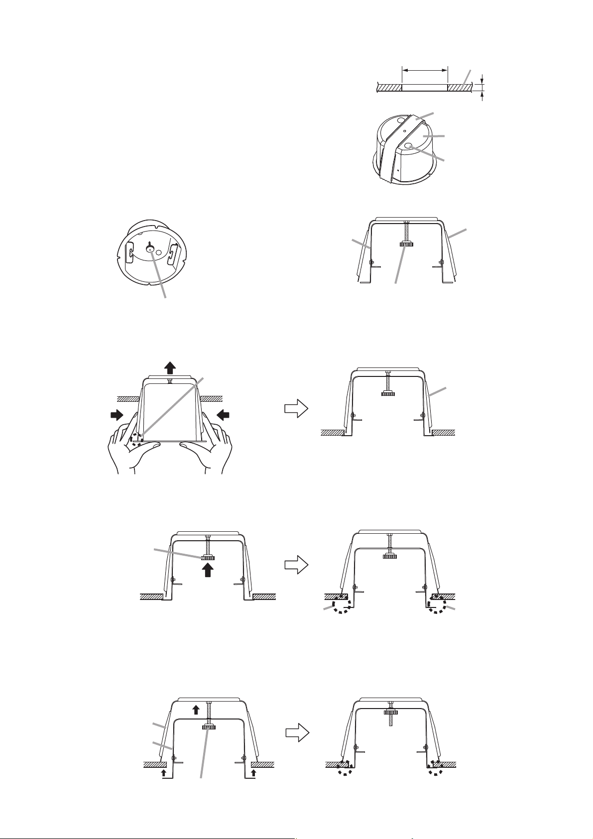
3. INSTALLATION
Step 1. Using the supplied paper pattern as a guide, open a 156 mm
±3 mm mounting hole in the ceiling panel.
Step 2. Punch out the knockout hole in the fire dome, then install the
supplied cable entry rubber grommet in the knockout hole.
Note: The grommet's cable entry hole is covered with a thin
membrane. Cut a hole in the membrane to match the
size of the speaker cable used.
Step 3. Loosen the dome mounting thumbnut.
[Interior View] [Cross-Section View]
Step 6. Push in the dome mounting thumbnut.
Firmly push the thumbnut and screw shaft
in the direction indicated by the arrow.
A
The legs of the dome mounting bracket will pop open
and settle on the back surface of the ceiling panel,
providing the dome with partial support. If released, a
gap behind the collar of the dome will result (A).
Step 7.
Turn the dome mounting thumbnut clockwise to tighten and firmly secure the dome to the ceiling panel.
Step 4. Feed the speaker cable through the rubber grommet into the dome interior.
Step 5. Press the fire dome assembly into the previously prepared hole in the ceiling.
ø156 ±3 mm
Ceiling
Max. 30 mm
Fire dome
Important
Dome mounting thumbnut
Unscrew the dome mounting thumbnut
until it reaches the end of the screw shaft.
Each leg should settle
on the collar.
Dome mounting bracket
Fire dome
ø20 mm knockout hole
(2 places)
Dome mounting
bracket
Dome mounting
bracket
Push up the dome assembly pressing
the bracket sides with your fingers.
Dome mounting
thumbnut
Dome mounting bracket
Fire dome
Caution
Since the dome mounting bracket is not placed on the
ceiling panel at this stage, as shown in the above figure,
the dome could fall if released, so continue to provide
manual support.
A
Dome mounting thumbnut Tighten fully for a secure installation.
Page 3

Step 8. Connect the speaker cable.
Wire the speaker according to the terminal indication.
Note: Hook the two ends of one of the speaker
mounting springs into the hooks in the fire
dome during connection.
Step 9. Hook the remaining speaker mounting spring into its
corresponding hook in the dome, then push the
speaker up into the fire dome.
Caution
Do not press directly on the front grille, as the grille
could become dented or damaged.
Note
See to it that the speaker cable is not pinched between
the fire dome and the front grille.
4. INSTALLING THE SAFETY WIRE (prepared separately by the installer)
Step 1. Tie one end of the safety wire around the terminal fitting
metal.
Note: When using a bare safety wire, wrap insulation
tape around it to prevent electrical contact with
the connection terminals, transformer taps, or
other electric parts.
Step 2. Make a cut in the rubber grommet with a knife or a
screwdriver, then run the safety wire through it.
Step 3. Tie snap ring around a secure channel bar or
suspension bracket.
Step 4. Feed the speaker cable through the rubber grommet
into the dome interior.
Step 5. Secure the fire dome assembly in the ceiling, then
connect the speaker cable to the terminal block.
Step 6. Attach the speaker to the fire dome.
Note: If the speaker cable and safety wire are too long,
to prevent them from being tangled inside the fire
dome, gently push them back out of the fire dome
so the rubber grommet does not get removed.
Fire dome mounted
to the ceiling
PC-1867FC shown.
Wiring diagram
• PC-1867F
3 W (3.3 kΩ)
6 W (1.7 kΩ)
COM
Bridging terminal
Terminal
BRN
BLK
WHT
13 kΩ
6.7 kΩ
3.3 kΩ
1.7 kΩ
COM
(Factory-preset transformer connection)
8 Ω
0
Speaker cable
Speaker mounting
spring
Terminal block
• PC-1867F:
• PC-1867FC:
[PC-1867F terminal block (1.7 kΩ use)]
• When no bridge connection
is made
COM
9 mm
Push-in terminal
Screw terminal
6 W (1.7 kΩ)
• When making a bridge
connection
From Amplifier
COM
6 W (1.7 kΩ)
9 mm
9 mm
Push-in terminalPush-in terminal
To the next speaker
Speaker mounting
spring
[PC-1867FC terminal block (1.7 kΩ use)]
• When no bridge connection
is made
Screw terminal
Earth
6 W (1.7 kΩ)
• PC-1867FC
Steatite
Terminal
Earth
6 W (1.7 kΩ)
COM
Thermal fuse (72°C)
5 mm
COM
Speaker mounting
spring
Incombustible cable
13 kΩ
6.7 kΩ
3.3 kΩ
1.7 kΩ
COM
(Factory-preset transformer connection)
8 Ω
• When making a bridge
connection
Screw terminal
Earth
From
Amplifier
6 W (1.7 kΩ)
To the next speaker
0
5 mm
COM
Dome mounting
bracket
Secure channel bar or
suspension bracket
Snap ring
Ceiling
Fire dome
Safety wire
(prepared separately)
Rubber grommet
Front grille
Terminal fitting
metal
Page 4

5. SPECIFICATIONS
Notes
• The design and specifications are subject to change without notice for improvement.
• The Specifications data was measured in an anechoic chamber.
• Reference axis: Axis is on the center of grill surface and perpendicular to the grill surface.
• Reference plane: Plane is on the grill surface and perpendicular to the reference axis.
• Horizontal plane: Plane is containing the reference axis and perpendicular to the reference plane.
• Other technical data: See the specification sheet PC-1867F/FC.
• Accessories
Rubber grommet ........................................ 2 Paper pattern ............................................. 1
533-06-088-7D
URL: http://www.toa.jp/
PC-1867F PC-1867FC
6 W (100 V line), 3 W (70 V line)
100 V line:1.7 kΩ (6 W), 3.3 kΩ (3 W), 6.7 kΩ (1.5 W), 13 kΩ (0.8 W)
70 V line: 1.7 kΩ (3 W), 3.3 kΩ (1.5 W), 6.7 kΩ (0.8 W), 13 kΩ (0.4 W)
6.7 kΩ, 13 kΩ: Internal 3.3 kΩ, 6.7 kΩ, 13 kΩ: Internal wiring must be changed.
wiring must be changed.
90 dB at 1 W, 1 m (500 Hz – 5 kHz, pink noise)
79 dB at 1 W, 4 m (100 Hz – 10 kHz, pink noise) according to EN 54-24
91 dB at 1 W, 1 m (100 Hz – 10 kHz, pink noise) converted based on EN 54-24
85 dB at 6 W, 4 m (100 Hz – 10 kHz, pink noise) according to EN 54-24
97 dB at 6 W, 1 m (100 Hz – 10 kHz, pink noise) converted based on EN 54-24
100 Hz – 16 kHz 160 Hz – 13 kHz
(without fire dome)
500 Hz: 186°; 1 kHz: 178°; 2 kHz: 148°; 4 kHz: 76°; according to EN 54-24
12 cm cone type
The European Standard EN 54-24: 2008 1438/CPD/0183 Certified year: 10
Loudspeaker for voice alarm systems for fire detection
and fire alarm systems
Environmental type: A (Indoor applications)
In compliance with the British Standard
BS 5839-8: 2008
ø156
± 3 (mounting hole) x 30 (maximum ceiling thickness) mm
Spring catch
Solid wire: ø0.8 – ø1.6 mm Solid wire: ø1.0 – ø3.0 mm (AWG 18 – 9)
(AWG 20 – 14)
7-core twisted wire:
0.75– 1.25 mm
2
(AWG 18 – 16)
Push-in connector Screw connector
(Bridging terminal) (Steatite terminal) bridging
Baffle: Aluminum, off-white (RAL 9010 or equivalent color), paint
Grille: Aluminum net, off-white (RAL 9010 or equivalent color), paint
Dome mounting bracket: Steel plate, trivalent chromate treatment plating
Fire dome: Steel plate, black, paint
ø180 x 11 (exposed section) + 110 (d) mm (excluding dome mounting bracket)
1.4 kg (including bracket and fire dome)
Model No.
Rated Input
Rated Impedance
Sensitivity
Maximum
Sound Pressure Level
Frequency Response
Coverage Angle (–6 dB)
Speaker Component
Standard
Dimensions for Fixing
Hole
Speaker Mounting
Method
Applicable Cable
Connection
Finish
Dimensions
Weight
Traceability Information for Europe
Manufacturer:
TOA Corporation
7-2-1, Minatojima Nakamachi, Chuo-ku, Kobe, Hyogo, Japan
Authorized representative:
TOA Electronics Europe GmbH
Suederstrasse 282, 20537 Hamburg, Germany
1438
 Loading...