

Toa PC-1860S Installation Manual
INSTALLATION
MANUAL
CEILING MOUNT SPEAKER
PC-1860S
Thank you for purchasing TOA’s Ceiling Mount Speaker.
Please carefully follow the instructions in this manual to
ensure long, trouble-free use of your equipment.
1. SAFETY PRECAUTIONS
• Before installation or use, be sure to carefully read
all the instructions in this section for correct and
safe operation.
• Be sure to follow all the precautionary instructions
in this section, which contain important warnings
and/or cautions regarding safety.
• After reading, keep this manual handy for future
reference.
WARNING
Indicates a potentially hazardous situation which,
if mishandled, could result in death or serious
personal injury.
• Install the unit only in a location that can structurally
support the weight of the unit and the mounting
bracket. Doing otherwise may result in the unit
falling down and causing personal injury and/or
property damage.
• Do not use other methods than specied to mount
the unit. Extreme force is applied to the unit and
the unit could fall off, possibly resulting in personal
injuries.
CAUTION
Indicates a potentially hazardous situation which,
if mishandled, could result in moderate or minor
personal injury, and/or property damage.
• Avoid touching the unit's sharp metal edge to
prevent injury.
• To avoid electric shocks, be sure to switch off the
amplier's power when connecting speakers.
• Do not operate the unit for an extended period of
time with the sound distorting. This is an indication
of a malfunction, which in turn can cause heat to
generate and result in a re.
2. GENERAL DESCRIPTION
Integrated with a speaker unit and panel, the PC-1860S
Ceiling Mount Speaker is of metallic construction and ideal
for use in a voice alarm system. It features spring catch
mechanism for easy speaker mounting to the ceiling.
The input impedance can be easily changed by changing
the tap position of the transformer.
The push-in type input terminal block makes cable
connections easy and allows bridge wiring.
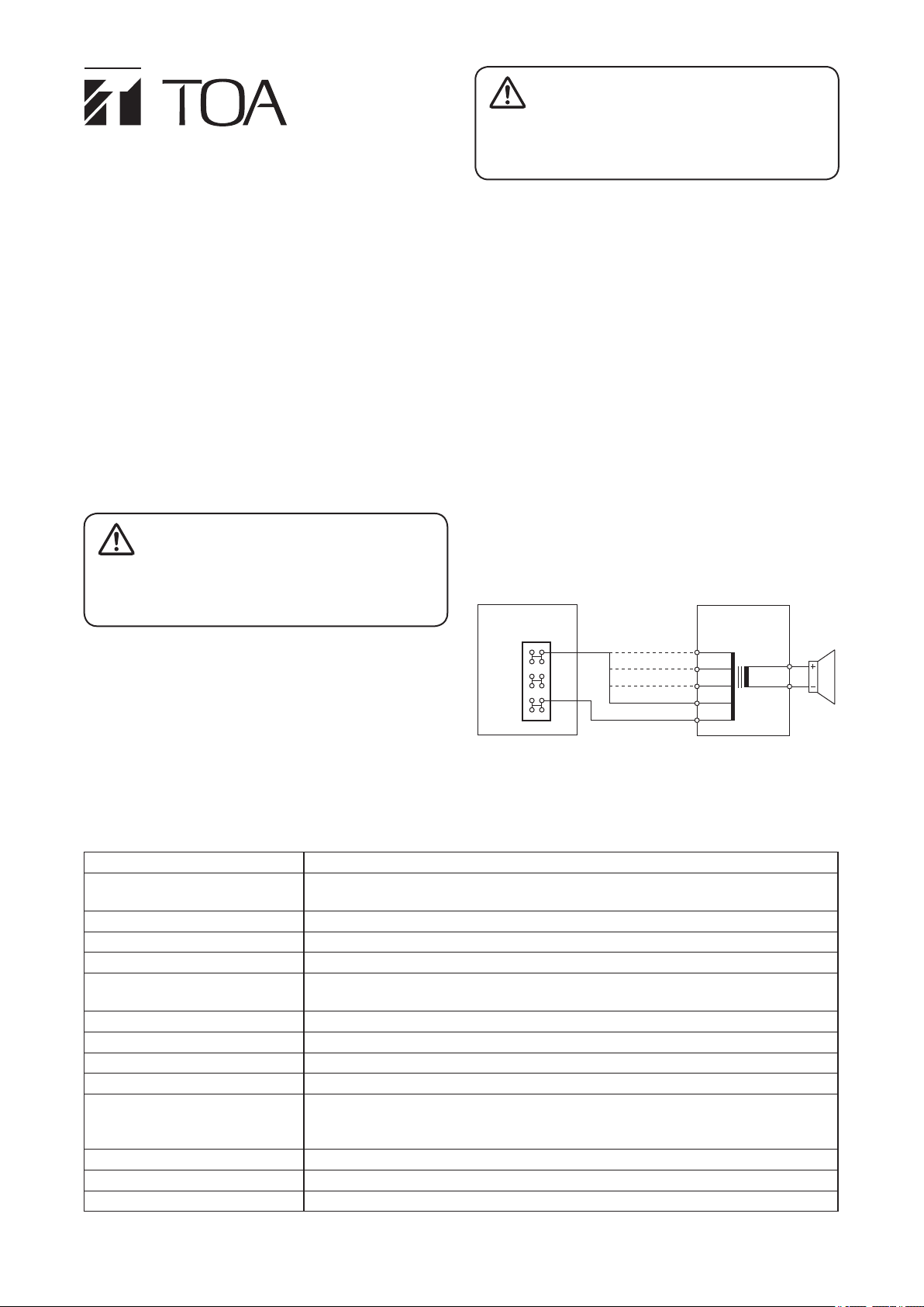
3. WIRING DIAGRAM
Input connector
HOT
(+)
COM
(–)
HOT (black)
COM (white)
13 kΩ
6.7 kΩ
3.3 kΩ
1.7 kΩ*
COM
Matching
transformer
8 Ω
0
* Factory-preset
4. SPECIFICATIONS
Rated Input 6 W (100 V line), 3 W (70 V line)
Rated Impedance 100 V line: 1.7 kΩ (6 W), 3.3 kΩ (3 W), 6.7 kΩ (1.5 W), 13 kΩ (0.8 W)
70 V line: 1.7 kΩ (3 W), 3.3 kΩ (1.5 W), 6.7 kΩ (0.8 W), 13 kΩ (0.4 W)
Sensitivity 94 dB (1 W, 1 m) (500 Hz – 5 kHz, pink noise)
Frequency Response 80 Hz – 20 kHz (peak –20 dB)
Speaker Component 12 cm (5") cone-type
Dimensions for Fixing Hole Mounting hole: ø150 ±3 mm (ø5.91" ±0.12")
Ceiling thickness: 5 – 25 mm (0.2" – 0.98")
Speaker Mounting Method Spring catch
Operating Temperature –10 to +50 °C (14 to 122 °F)
Applicable Cable Solid wire: 0.5 – 3 mm² (AWG 20 – 12)
Connection Push wire connection (Bridging terminal-2 branch type)
Finish Frame: Steel plate, white (RAL 9016 equivalent), paint
Grille: Steel net, white (RAL 9016 equivalent), paint
Mounting bracket: Steel plate, plating
Dimensions ø180 x 5 (exposed section) + 101 (d) mm (ø7.09" x 0.2" + 3.98")
Weight 750 g (1.65 lb)
Accessory Paper pattern ................................... 1
Note: The design and specications are subject to change without notice for improvement.
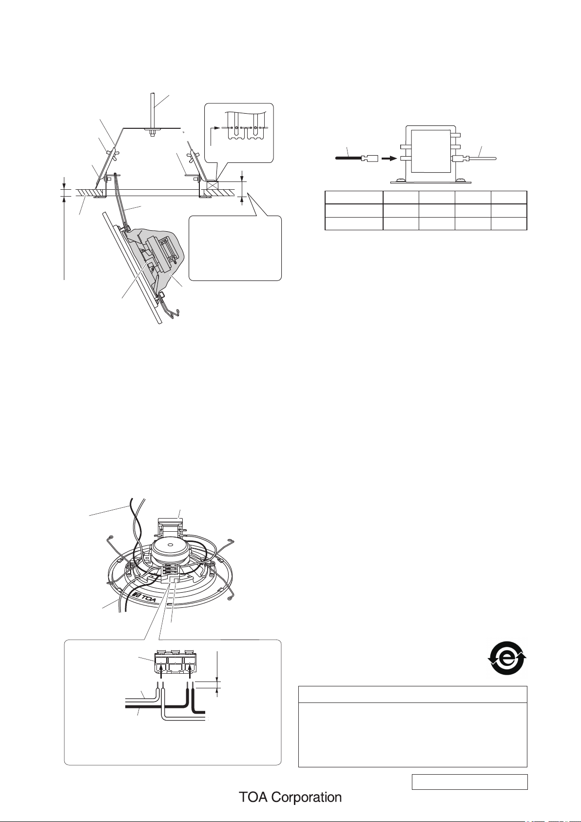
5. INSTALLATION
Step 1. Make a 150 ±3 mm (5.91" ±0.12") diameter hole in
the ceiling.
Suspension bolt
Mounting bracket
4-2. Change the input impedance as needed.
The speaker's input is factory-preset to 1.7 kΩ.
When changing the input impedance, detach the
black wire connected to the matching transformer,
and reinsert it into the desired input tap referring
to the table below.
Matching transformer
Thumb screw
Spring catcher
Ceiling clamp
2
Bent position
3
Speaker spring
Ceiling
25 mm (0.98") max.
Input connector
Step 2. Place the mounting bracket in the hole and secure
it with the thumb screws in the two ceiling clamps.
Note
A suspension bolt may be used instead for xing
the mounting bracket.
Step 3. Hook one speaker spring (V-shaped spring) in the
spring catcher of the bracket.
Note
Max. 30 mm (1.18")
allowable with the
ceiling clamp bent
as designated above.
Cloth dust cover
(with the input connector exposed)
HOT (Black) COM (White)
1.7kΩ
3.3kΩ
13kΩ
6.7kΩ
COM
Impedance 1.7 kΩ 3.3 kΩ 6.7 kΩ 13 kΩ
100 V line 6 W 3 W 1.5 W 0.8 W
70 V line 3 W 1.5 W 0.8 W 0.4 W
Step 5. Hook another speaker spring in another catcher.
Then, press the speaker assembly into the
mounting bracket. Force of the springs will keep
the speaker in place.
Step 4. Make wiring.
4-1. Insert the lead-in cables (cables from the amplier)
and lead-out cables (cables to other speakers)
into the input connector.
[When making a bridge connection]
Matching transformer
Speaker cable
(From the amplifier)
Speaker cable
(To the next speaker)
Input connector
COM (–)
From
the amplifier
HOT (+)
Applicable cable
Solid wire: ø0.8 – ø1.6 mm
(equivalent to AWG 20 – 14)
View with dust cover removed
Input connector
9 mm
(0.35")
To
the next speaker
Traceability Information for Europe
Manufacturer:
TOA Corporation
7-2-1, Minatojima-Nakamachi, Chuo-ku, Kobe, Hyogo, Japan
Authorized representative:
TOA Electronics Europe GmbH
Suederstrasse 282, 20537 Hamburg, Germany
URL: https://www.toa.jp/
133-01-00247-00
 Loading...