

Toa PC-1860F, PC-1860BS-C, PC-1860BS Installation Manual
INSTALLATION MANUAL
CEILING MOUNT FIRE DOME SPEAKER
PC-1860F, PC-1860BS, PC-1860BS-C
Thank you for purchasing TOA’s Ceiling Mount Fire Dome Speaker.
Please carefully follow the instructions in this manual to ensure long, trouble-free use of your equipment.
1. SAFETY PRECAUTIONS
CAUTION
• Before installation or use, be sure to carefully read
all the instructions in this section for correct and
safe operation.
• Be sure to follow all the precautionary instructions
in this section, which contain important warnings
and/or cautions regarding safety.
• After reading, keep this manual handy for future
reference.
WARNING
Indicates a potentially hazardous situation which,
if mishandled, could result in death or serious
personal injury.
• Use only the specied amplier output voltage
and impedance, as exceeding the specied limits
could result in re or other failures (high-impedance
applications).
• To avoid accidental air explosions, do not use the
unit around gasoline, thinner or other combustibles.
• Install the unit only in a location that can structurally
support the weight of the unit and the mounting
bracket. Doing otherwise may result in the unit
falling down and causing personal injury and/or
property damage.
• Do not use other methods than specied to mount
the unit. Extreme force is applied to the unit and
the unit could fall off, possibly resulting in personal
injuries.
• Tighten each nut and bolt securely. Ensure that
the bracket has no loose joints after installation
to prevent accidents that could result in personal
injury.
• Avoid mounting the unit in locations exposed to
constant vibration. The mounting bracket can be
damaged by excessive vibration, potentially causing
the speaker to fall, which could result in personal
injury.
Indicates a potentially hazardous situation which,
if mishandled, could result in moderate or minor
personal injury, and/or property damage.
• To avoid electric shocks, be sure to switch off the
amplier power when connecting the speaker.
• Avoid installing the unit in humid or dusty locations,
or in locations exposed to heaters, solvents, acid,
alkali, smoke, or steam, as excessive exposure to
these factors could result in the speaker falling off,
electric shock or re.
• Do not operate the unit for an extended period of
time with the sound distorting. This is an indication
of a malfunction, which in turn can cause heat to
generate and result in a re.
• Have the unit periodically checked by the shop
from where it was purchased. Failure to do so could
result in the speaker falling off due to damage or
corrosion to the speaker or its mounts, and possible
personal injury.
2. GENERAL DESCRIPTION
TOA's PC-1860F, PC-1860BS, and PC-1860BS-C
Ceiling Mount Fire Dome Speakers feature an ironmade dome that prevents the re from spreading in
the ceiling in case of re.
The speaker can be easily installed using the speaker
mounting spring, and the dome can also be easily
mounted in the speaker mounting hole in the ceiling
panel.
The PC-1860F comes with a push-in type input terminal
block that permits one-touch cable connection as well
as bridging and branch wiring, while the PC-1860BS/
PC-1860BS-C are provided with a steatite terminal
block of screw type.
The PC-1860BS/PC-1860BS-C are certied according
to the European Standard EN 54-24: 2008 and
compliant with the British Standard BS 5839-8: 2008.
Traceability Information for Europe
Manufacturer:
TOA Corporation
7-2-1, Minatojima-Nakamachi, Chuo-ku, Kobe, Hyogo, Japan
Authorized representative:
TOA Electronics Europe GmbH
Suederstrasse 282, 20537 Hamburg, Germany
3. INSTALLATION
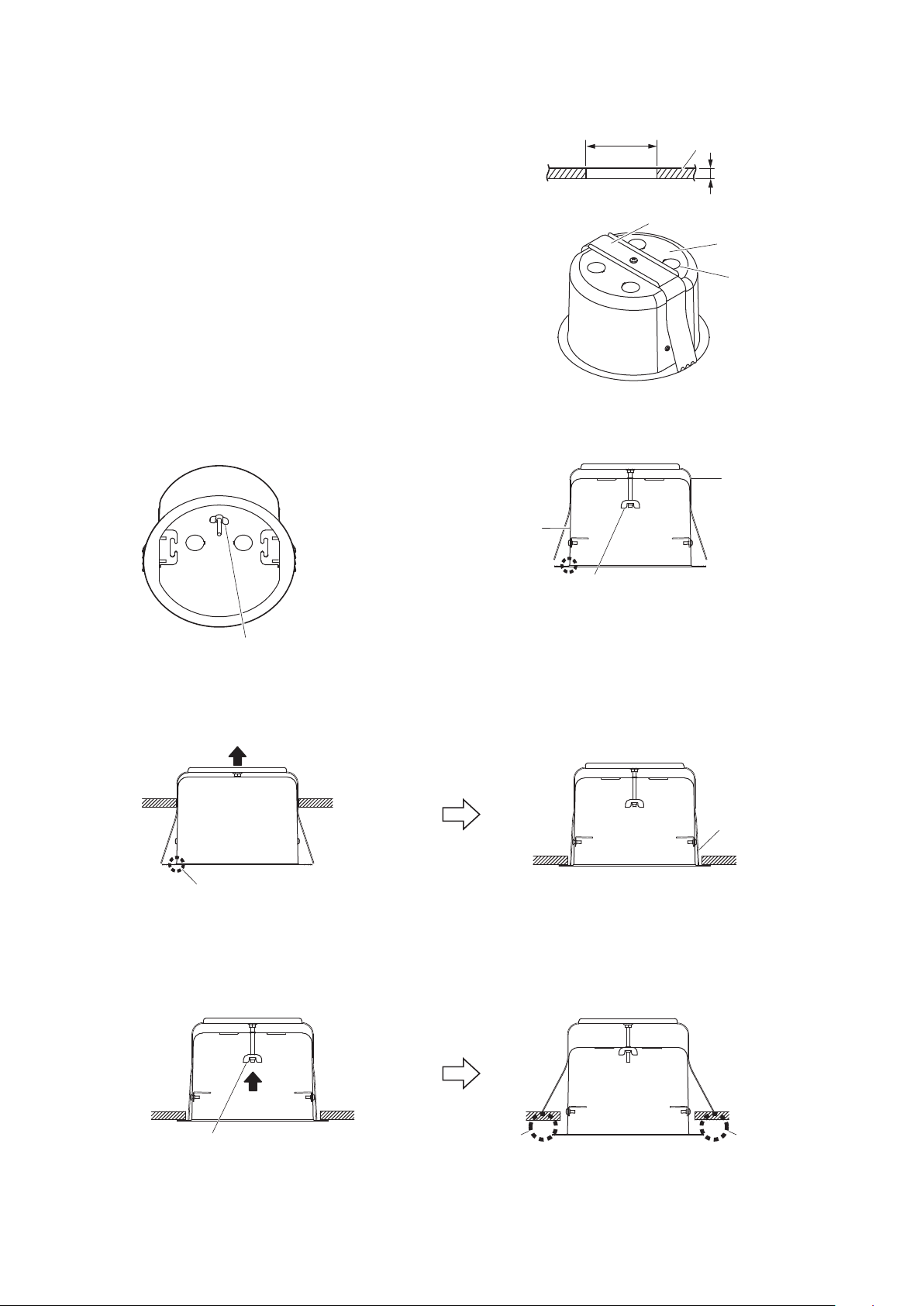
Step 1. Using the supplied paper pattern as a guide, open a
156 mm (6.14") ±3 mm (0.12") mounting hole in the
ceiling panel.
Step 2. Punch out the knockout hole in the re dome, then
install the supplied cable entry rubber grommet in
the knockout hole.
Note: The grommet's cable entry hole is covered
with a thin membrane. Cut a hole in the
membrane to match the size of the speaker
cable used.
Step 3. Loosen the wing nut.
[Cross-Section View] [Interior View]
Fire dome
ø156 ±3 mm
(ø6.14" ± 0.12")
Dome mounting bracket
Ceiling
Max. 30 mm (1.18")
Fire dome
ø20.5 mm (0.81")
knockout hole
(4 places)
Dome mounting
bracket
Important
Unscrew the wing nut until it reaches
the end of the screw shaft.
Wing nut
Step 4. Feed the speaker cable through the rubber grommet into the dome interior.
Step 5. Press the re dome assembly into the previously prepared hole in the ceiling.
Each leg should settle on the collar.
Push up the dome assembly.
Caution
Since the dome mounting bracket is not placed on the
ceiling panel at this stage, as shown in the above gure,
the dome could fall if released, so continue to provide
manual support.
Step 6. Push in the dome mounting wing nut.
Dome mounting
bracket
2
Wing nut
Firmly push the wing nut and screw shaft
in the direction indicated by the arrow.
A
The legs of the dome mounting bracket will pop open and
settle on the back surface of the ceiling panel, providing
the dome with partial support. If released, a gap behind
the collar of the dome will result (A).
A
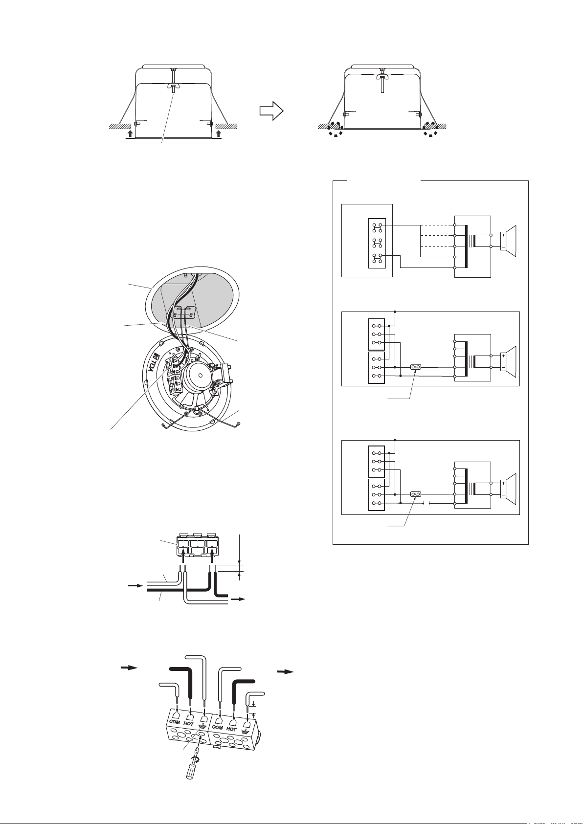
Step 7. Turn the dome mounting wing nut clockwise to tighten and rmly secure the dome to the ceiling panel.
6 W (1.7 kΩ)
Wing nut
Tighten fully for a secure installation.
Step 8. Make wiring.
8-1. Insert the lead-in cables (cables from the amplifier)
and lead-out cables (cables to other speakers) into the
input connector according to the terminal indication.
Note: Hook the two ends of one of the speaker
mounting springs into the hooks in the re
dome during connection.
Fire dome mounted
to the ceiling
Speaker cable
Terminal block
• PC-1860F:
• PC-1860BS:
• PC-1860BS-C:
Push-in type input terminal
Steatite terminal
Steatite terminal
[PC-1860F terminal block]
When making a bridge connection:
Push-in type
input terminal
COM
From
the amplifier
The gure shows
PC -18 6 0 BS .
Speaker mounting
spring
Speaker mounting
spring
9 mm
(0.35")
To
the next speaker
Wiring diagram
• PC-1860F
Input connector
HOT
(+)
COM
(–)
• PC-1860BS
Input connector
Earth
HOT
COM
Earth
HOT
COM
Thermal fuse
(72 ºC or 161.6 ºF)
• PC-1860BS-C
Input connector
Earth
HOT
COM
Earth
HOT
COM
Thermal fuse
(72 ºC or 161.6 ºF)
HOT
(black)
COM
(white)
13 kΩ
6.7 kΩ
3.3 kΩ
1.7 kΩ*
COM
13 kΩ
6.7 kΩ
3.3 kΩ
1.7 kΩ*
COM
13 kΩ
6.7 kΩ
3.3 kΩ
1.7 kΩ*
COM
1 µF 250 V
Matching
transformer
8 Ω
0
* Factory-preset
Matching
transformer
8 Ω
0
* Factory-preset
Matching
transformer
8 Ω
0
* Factory-preset
[PC-1860BS/1860BS-C terminal block]
When making a bridge connection:
From
Amplifier
Earth
HOT
COM
Steatite terminal
COM
HOT
Earth
5 mm
To
the next speaker
3
 Loading...