

Toa PC-139 Instruction Manual
1. SAFETY PRECAUTIONS
• Be sure to read the instructions in this section carefully before use.
• Make sure to observe the instructions in this manual as the conventions of safety symbols and messages
regarded as very important precautions are included.
• We also recommend you keep this instruction manual handy for future reference.
• Do not operate the unit for an extended period of time with the sound distorting. This is an indication of a
malfunction, which in turn can cause heat to generate and result in a fire.
• Install the unit only in a location that can structurally support the weight of the unit and the mounting bracket.
Doing otherwise may result in the unit falling down and causing personal injury and/or property damage.
• Tighten each nut and screw securely. Ensure that the mounting hardware has no loose joints after
installation to prevent accidents that could result in personal injury.
Please follow the instructions in this manual to obtain the optimum results from this unit.
We also recommend that you keep this manual handy for future reference.
PC-139HEAT-RESISTANT HORN SPEAKER
Ceiling Suspension Type
INSTRUCTION MANUAL
2. GENERAL DESCRIPTION
TOA's PC-139 is a high-efficiency, heat-resistant ceiling suspension-type speaker designed exclusively to be
used in conjunction with emergency broadcast systems.
3. SPECIFICATIONS
Indicates a potentially hazardous situation which, if mishandled, could
result in death or serious personal injury.
WARNING
Indicates a potentially hazardous situation which, if mishandled, could
result in moderate or minor personal injury, and/or property damage.
CAUTION
Note: The design and specifications are subject to change without notice for improvement.
• Included components
Speaker unit (with mounting bracket B) ...... 1
Mounting bracket A ...................................... 1
Suspension pipe .......................................... 1
Decorative cover .......................................... 1
M4 x 30 screw .............................................. 2
4.1 x 32 wood screw .................................... 2
Rated Input 1 W
Rated Impedance 10 kΩ
Sound Pressure Level 100 dB (1W, 1m)
Frequency Response 500 – 10,000Hz
Heat Resistance Operates normally for 15 minutes in air current of 380°C
Withstand Voltage 1 kV AC, 1 minute (between input terminal and body)
Insulation Resistance 500 V DC, over 10 MΩ (between input terminal and body)
Speaker Angle Adjustment Range Horizontal: 360° rotation, Vertical: 90° rotation
Mounting Pitch 65 – 85 mm
Finish Speaker: Incombustible material (aluminum), off-white, paint
Weight 1.7 kg (including mounting brackets and hardware)
133-01-096-7B
k
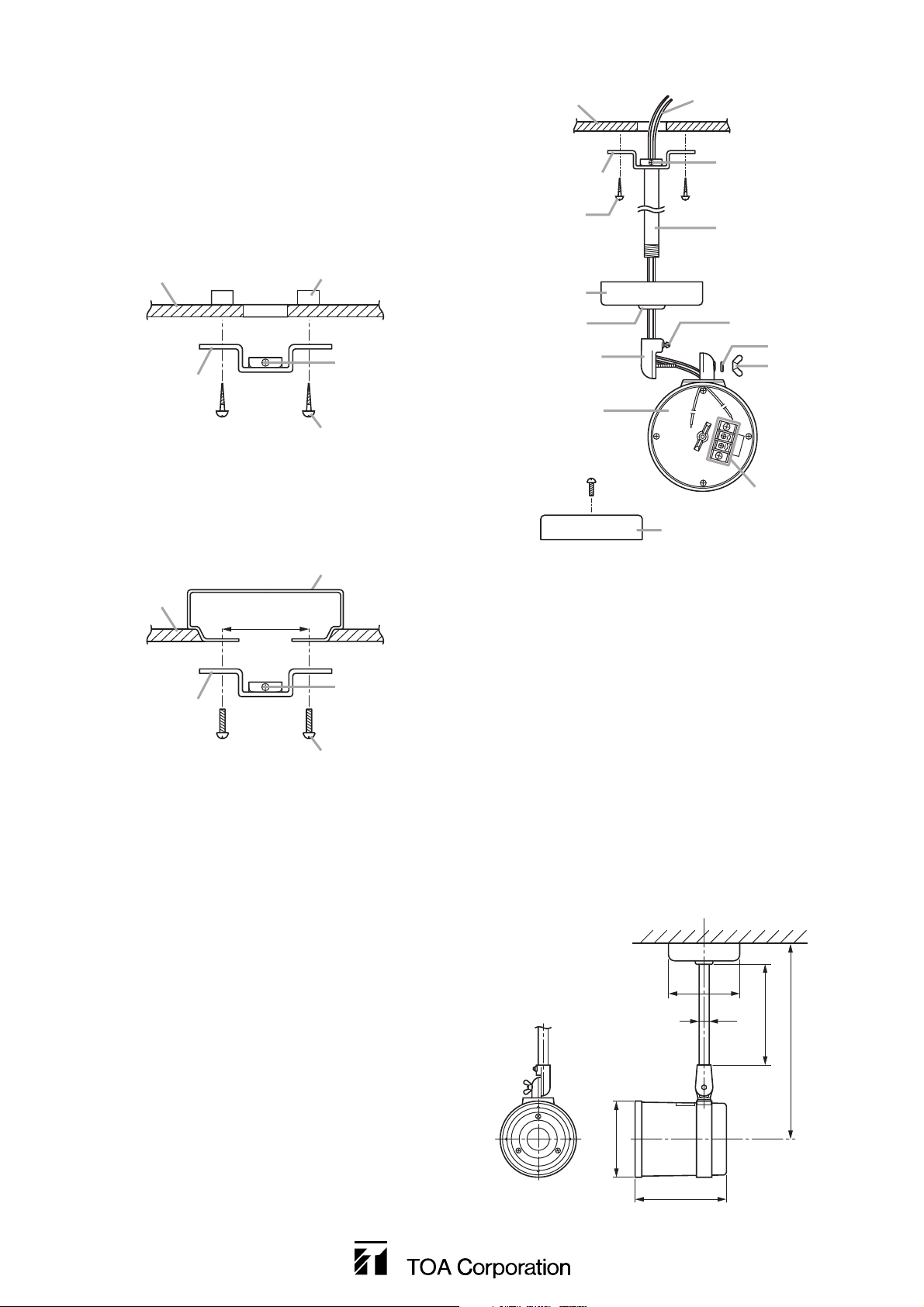
4. INSTALLATION
Be sure to mount and connect all parts correctly
AFTER feeding the speaker cable through the
suspension pipe.
Step 1. Attach Mounting Bracket A to the ceiling or
an outlet box using the supplied screws.
1-1. Ceiling Mounting
1-2. Mounting to an Outlet Box
Note
Prepare an outlet box (not supplied with the
unit) for mounting behind the ceiling panel.
6. DIMENSIONAL DIAGRAM
5. SPEAKER ANGLE ADJUSTMENT
Step 1. Loosen both Mounting Screw B and the wing
nut securing the speaker.
Step 2. Adjust the speaker angle.
• Rotate Mounting Bracket B to adjust
horizontal angle.
• Move the speaker itself to adjust vertical
angle.
Step 3. After completing the positioning adjustment,
retighten both Mounting Bracket B and the
wing nut.
Step 2. Insert the suspension pipe through the
center hole of Mounting Bracket A, installed
in Step 1, then tighten Mounting Screw A to
secure the pipe.
Step 3. Mount the decorative cover.
Note
Slowly slide the decorative cover over the
end of the mounting pipe while rotating it so
as not to dislodge its rubber grommet.
Step 4. Insert Mounting Bracket B into the
suspension pipe, then tighten Mounting
Screw B to secure the bracket.
Step 5. After first detaching its rear cover, mount the
speaker unit to Mounting Bracket B using
the supplied wing nut and washer.
Step 6. Connect the speaker cable leads to the
speaker unit's corresponding terminals.
Step 7. Reattach the speaker's rear cover.
Ceiling
Mounting bracket A
Supplied screws
Speaker cable
Mounting screw A
Suspension pipe
Ceiling
Mounting bracket A
Ceiling
Mounting bracket A
Mounting screw pitch
65 – 85 mm
Reinforcements
Mounting screw A
4.1 x 32 wood screw
Outlet box
Mounting screw A
M4 x 30 screw
Decorative cover
Rubber grommet
Mounting bracket B
Speaker unit
(with the rear cover off)
Rear cover
Mounting screw B
Washer
Wing nut
Terminal bloc
ø114
ø16
ø122
146
180
310
Unit: mm
 Loading...