

Toa PC-129 Instruction Manual
1. SAFETY PRECAUTIONS
• Be sure to read the instructions in this section
carefully before use.
• Make sure to observe the instructions in this
manual as the conventions of safety symbols and
messages regarded as very important precautions
are included.
• We also recommend you keep this instruction
manual handy for future reference.
Safety Symbol and Message Conventions
Safety symbols and messages described below are
used in this manual to prevent bodily injury and
property damage which could result from
mishandling. Before operating your product, read this
manual first and understand the safety symbols and
messages so you are thoroughly aware of the
potential safety hazards.
When Installing the Unit
• Install the unit only in a location that can
structurally support the weight of the unit and the
mounting bracket. Doing otherwise may result in
the unit falling down and causing personal injury
and/or property damage.
• Tighten each nut and screw securely. Ensure that
the mounting hardware has no loose joints after
installation to prevent accidents that could result in
personal injury.
When the Unit is in Use
• Do not operate the unit for an extended period of
time with the sound distorting. This is an indication
of a malfunction, which in turn can cause heat to
generate and result in a fire.
Please follow the instructions in this manual to obtain the optimum results from this unit.
We also recommend that you keep this manual handy for future reference.
PC-129HEAT-RESISTANT HORN SPEAKER
Flush-Mount Type
INSTRUCTION MANUAL
Indicates a potentially hazardous situation which,
if mishandled, could result in death or serious
personal injury.
Indicates a potentially hazardous situation which,
if mishandled, could result in moderate or minor
personal injury, and/or property damage.
WARNING
CAUTION
WARNING
CAUTION
Rated Input 1 W
Rated Impedance 10 kΩ
Output Sound Pressure Level 100 dB (1W, 1 m)
Frequency Response 500 – 8,000 Hz
Heat Resistance Operates normally for 15 minutes in air current of 380°C
Withstand Voltage 1 kV AC, 1 minute (between input terminal and body)
Insulation Resistance 500 V DC, over 10 MΩ (between input terminal and body)
Mounting Hole ø133 X 30 (maximum board thickness) mm
Speaker Cord Length 30 cm
Finish Speaker: Incombustible material (aluminum) , off white, paint
Dimensions ø166 x 140 (d) mm
Weight 1.6 kg (including mounting hardware)
2. SPECIFICATIONS
Note: The design and specifications are subject to change without notice for improvement.
133-01-094-7B
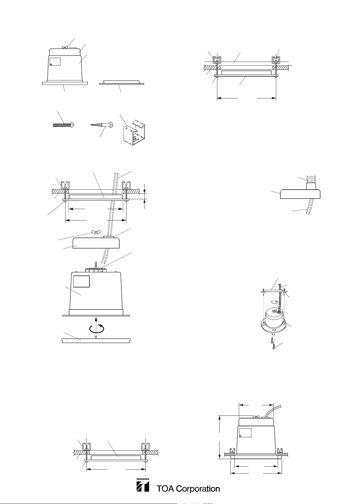
4. INSTALLATION
Step 1. Drill a hole with diameter of 130 mm in the
ceiling.
Step 2. Mount the speaker mounting frame to the
ceiling.
Note
Leave the space of 4 –5 mm between the
frame and the ceiling panel surface as
shown in the above figure without completely
fitting the frame in the hole.
2-1. Refer to the figure below when directly
mounting the frame to the ceiling panel.
2-2. Refer to the figure below when using the S
or W bar to mount the frame.
Note: Procure the S bar separately.
Step 3. Run the speaker cable through the cable
entry bushing in the terminal cover and
connect the cable to the terminal.
Notes
• When installing a piping, remove the rubber
bushing in the terminal cover, then insert a
flexible conduit into the 22 mm-diameter
round hole.
• Auxiliary terminal
When connecting wires at the speaker
terminal, use the auxiliary terminal for
connection of R line (simultaneous all-zone
call).
Step 4. Tighten the terminal cover using a wing nut.
Step 5. Mount the speaker unit.
Align the supplied
mounting screw
head with the bottleshaped hole in the
speaker unit, and
rotate the screw
clockwise to fix the
speaker. Also, use
the supplied wood
screws to secure
the speaker from
the oval holes in the
speaker unit.
Step 6. Mount the front grille.
Turn the grille clockwise to tighten it.
5. FIGURE OF THE INSTALLED SPEAKER
Unit: mm
Speaker mounting frame
Speaker cable
M4X40
mounting screw
Bottle-shaped
hole
4.1X32
wood screw
3. COMPONENTS USED
Frame mounting hardware
(2 pieces)
M4X40 mounting screw
(2 pieces)
4.1X32 wood screw
(2 pieces)
Wing nut
Terminal cover
Speaker unit
Front grille
Speaker mounting frame
Frame mounting hardware
Speaker mounting frame
Speaker cable
Frame mounting
hardware
Ceiling panel
Mounting screw
S bar or W bar
Speaker mounting frame
150 mm
S bar
(Procure separately.)
Flexibleconduit
Terminalcover
Ceiling panel
M4X40
mounting screw
Wing nut
Terminal cover
Speaker unit
Front grille
ø130 mm
150 mm
Leave space
of 4 – 5 mm.
Rubber bushing
Terminal
Frame mounting
hardware
Speakermountingframe
Speakercable
ø112
140
Ceilingpanel
Mountingscrew
150mm
ø130
ø166
 Loading...