

Toa P-924A Operating Instructions Manual
Operation Instruction Manual
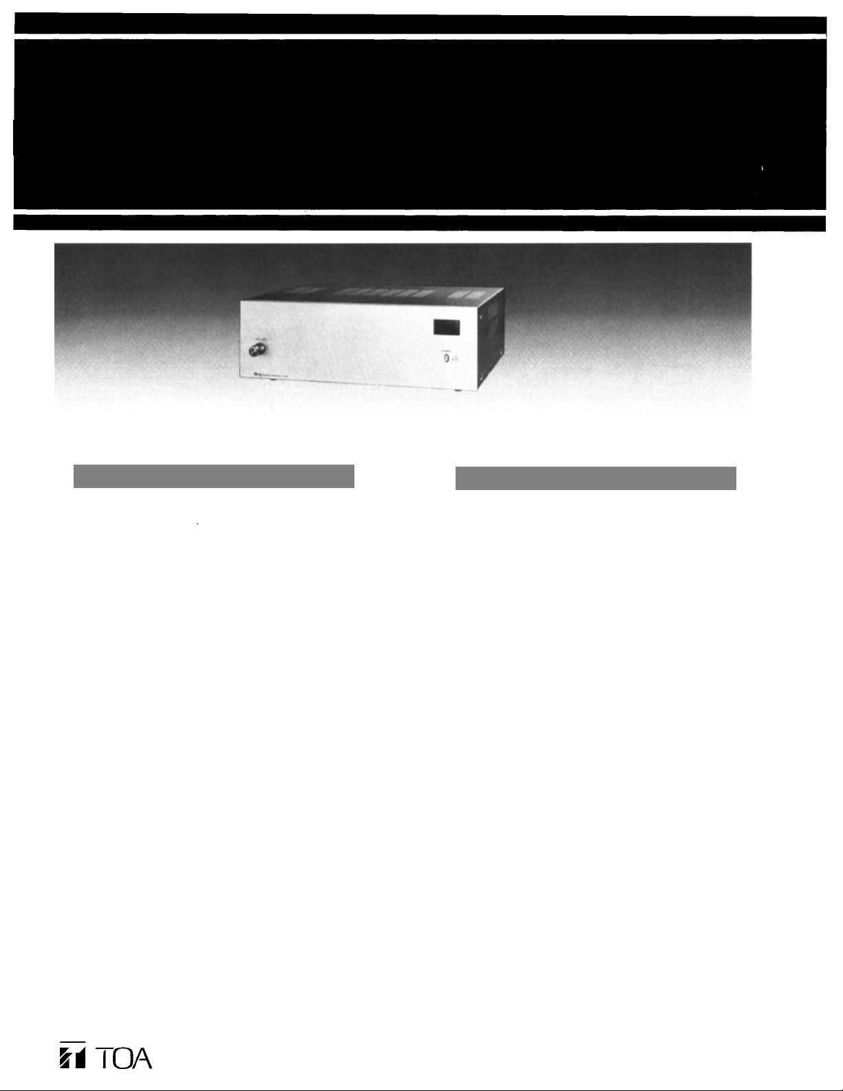
TOA 900 SERIES
POWER AMPLIFIER
Features
1 Wide frequency response; 20 — 20,000 Hz , ± 1 dB
2 Low distortion and noise level
3 Excellent output regulation
4
A ful l range of plug-in modules
5 Self-protecting circuitry design
6 Varied output impedances; 4 and 8 ohms, 25 and 7 0 volts
7 Input level switch (selectable 1,000mV/100mV)
8 Portable or rack-mounting type
P-924A
General Descriptions
The TOA P-924A Power Amplifier delivers up to 240 watts of power
at
less
than 0.5%
20,000 Hz (transformerless 4-ohm output). The P-924A has a highimpedance direct input and an input port (edge connector) to
accept one module accessory. Module selection is determined by
application among the TOA plug-in modules:
The M-01 series, M-03 series, M-51 series and M-61 series Microphone Prea mplifiers, R-01 Mag. Phono Preamplifier, the U-01 series,
U-21 series and U-61 series Auxiliary Preamplifiers for high-level
sources, the B-01 series Bridging Transformers for bridging highimpedance lines, the L-01 series Line Matching Transformers for
matching 600-ohm lines, and the S-01, S-02 and S-03 Tone signal
generators for generating attention-getting signals and 1 KHz sine
wave for testing within the total s ystem.
The P-924A has a low -cut swi tch f or cuto ff frequency of 60 Hz, and
an input-level switch for input sensitivity of 1V (0dBv) or 100mV
(—20dBv). Output terminals provide connections for 4-ohm and
8-ohm speakers, plus 25-volt and 70-volt speaker distribution
outlets.
With plug-in modules, the TOA P-924A Power Amplifier may be
used as a pre/power amplifier.
The P-924A can be rack mounted by using the MB-931A Rackmounting Bracket accessory. The PF-911 Perforated Panel (1.73
inches, 1 rack unit) accessory provides suitable ventilation, finished
in color to match the P-924A.
total
harmonic
distortion
(THD)
from
20 to
Toa Electric Co., Ltd.
KOBE, JA P A N
133-02-907-70
Printed in Japan
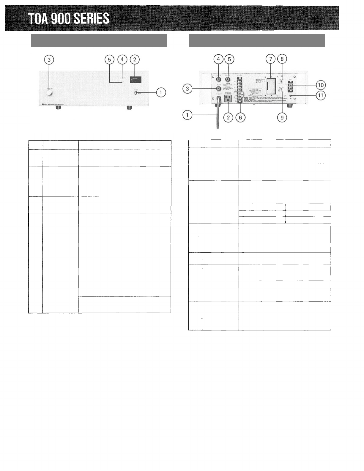
Front Panel Controls and Features
Rear Panel Controls and Features
Item
1
2
3
4
5
Name
POWER
ON-OFF
SWITCH
METER
INPUT
VOLUME
CONTROL
PROTECTION
INDICATOR
(RED)
NORMAL
INDICATOR
(GREEN)
Function/Description
Applies line power. Two-position
pushbutton switch for on-off modes.
Indicates the output level of the
amplifier. At rated output, it shows
0 VU (at continuous sine-wave
signal input).
When power is turned on , meter
illuminates.
Adjust gain of INPUT.
This LED indicator comes on and goes
out in about 5 seconds after the power
switch is turned on.
If the LED indicator remains lit
indicating that a muting relay is not
activated, turn the power switch off
after disconnecting the speaker line
and turn it on again. As a result,
1. if the LED indicator goes out in
about 5 seconds, the speaker line
may be short-circuited or
overloaded.
Check the speaker line.
2. unless the LED indicator still goes
out, abnormality has occurred in the
power amplifier stage.
Check the power amplifier stage.
Lights up when the amplifier is
normally working.
Item
1
2
3
4
5
6
7
8
9
10
11
Name
AC POWER
SUPPLY
CORD
AC OUTLET
(Unswitched)
AC FUSE
DC FUSE (-)
DC FUSE (+)
OUTPUT
TERMINALS
MODULE
INPUT
PORT
LOW-CUT
SWITCH
INPUT
LEVEL
SWITCH
DIRECT
INPUT
TERMINAL
EARTH
TERMINAL
Function /Description
Connects to pow er source.
Provides AC po w e r for auxiliary equipment with power consumption of up to
500W.
Protects amplifier from excessive current
drain. Replace only with same type fuse.
Refer to qualified servi ce personnel if
fuse blows repeatedly.
AC FUSE 250V 7A
DC FUSE (-) 250V 8A
DC FUSE (+) 250V 8A
Connect to speakers.
Accepts PLUG-IN MODULES which are
optionally available. Modul e selection is
determined by application.
Cuts off unnecessary low frequency.
Selects input sensitivity. Place in "1V
(0dBv)" position when normally used
as a power amplifier.
Note: The position of INPUT-LEVEL
SWITCH should b e cha nged according to
modules used or equipment connected to
DIRECT INPUT TERMINAL.
Connects directly to external equipment
without using modules. Unbalanced
10k ohms.
Normally connects to a record player's
ground.
— 1 —
Input Connections
• Two types of input terminals are provided on the rear for input
connections.
(1) 2P terminal (marked HOT, E)
It is provided fo r direct input (unbalanced, 10k ohms) without
using plug-in modules. This terminal is directly connected with
a potentiometer inside.
(2) Plug-in module input
Select the desired modules according to application.
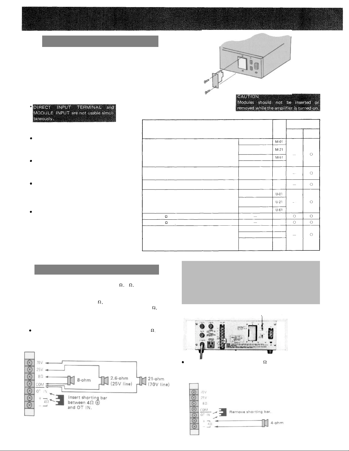
Plug-in Modules and Input Level SW Setting
Plug the module into INPUT PORT, sliding it between the guide rails, and secure
with two screws.
When INPUT PORT is not occupied, cover
the PORT with the blank panel, and
secure it with screws.
Be sure that INPUT-LEVEL SWITCH is in
the proper position for the modules used
or the equipment connected to DIRECT
INPUT TERMINAL.
When the P-924A is used in combination
with a mixer preamplifier or serves as an
incremental power amplifier, normally
place INPUT LEVEL SWITCH in "1V
(0dBv)" position.
Balanced low impedance microphone preamp. module
(with presettable low-cut filter, high-cut filter and gain
controls)
Unbalanced high impedance microphone preamp module
(with presettable low-cut filter, high-cut filter and gain
controls)
Equalized mag phono preamp module
(with presettable gain control)
Unbalanced high impedance auxiliary preamp. module
(with presettable gain control)
Balanced 10k
Balanced 600
Signal tone generator module
(with presettable output level control)
Plug-in Modules
bridging transformer module
bridging transformer module
Input level SW
Model
No.
—
Remote Volume
control
Voice Gate
Compressor
-
-
—
Remote Volume
control
Compressor
1kHz Sine Wave
Yelp and buzzer
One-tone chime and
continuous one-tone
chime
*See PLUG-IN MODULES for detail.
M-61
M-03
R-01
B-01
L-01
S-01
S-02
S-03
1V
(0dBV)
Setting
100mV
(—20dBV)
Output Connections P-924A
The speaker outputs of the amplifier are 4
8
25V and
Connect speakers to one of these outputs.
Class 2 wiring may be used.
Since these outputs consist of 8
25V and 70V via the output
transformer (matching transformer) and direct output of 4
connecting method differs in each case. See the following diagrams.
Note: Impedances indicated below imply total speaker system
(load) impedance.
When connecting speakers to any one of the outputs of 8
or 70V (BALANCED TRANSFORMER OUTPUT);
<P-924A>
70V.
the
25V
Note:
In this case, the LOW-CUT SWITCH should be "CUT" posi-
tion.
This
amplifier
is
characteristically
flat
even
in the low
quency range. Therefore, in TRANS OUTPUT, the acoustic
effect and frequency-response characteristics may be altered.
In TRANS OUTPUT, cut of f unnecessary low frequency t o ob-
tain the best acoustic condition.
Place the LOW-CUT
SWITCH in "CUT" position
When connecting speakers to the 4
output. (UNBLANCED
DIRECT OUTPUT);
<P-924A>
fre-
— 2 —
 Loading...