

Page 1
OPERATING INSTRUCTIONS
DIGITAL STEREO MIXER M-633D
Thank you for purchasing TOA's Digital Stereo Mixer.
Please carefully follow the instructions in this manual to ensure long, trouble-free use of your equipment.
Page 2

2
TABLE OF CONTENTS
1. IMPORTANT SAFETY INSTRUCTIONS ........................................................... 3
2. SAFETY PRECAUTIONS ....................................................................................... 4
3. GENERAL DESCRIPTION .................................................................................... 6
4. FEATURES ................................................................................................................. 6
5. HANDLING PRECAUTIONS ................................................................................. 6
6. NOMENCLATURE AND FUNCTIONS
Front ................................................................................................................................ 7
Rear ................................................................................................................................ 8
7. ASSIGNMENT SETTINGS ..................................................................................... 9
8. USING THE SUMMING OUTPUT KEYS.......................................................... 10
9. SETTING THE ARC FUNCTION
9.1. What is the Automatic Resonance Control (ARC) Function? ................................. 11
9.2. Outline of the ARC Function Settings .................................................................... 11
9.3. Enabling the ARC Function .................................................................................... 13
9.4. Making Fine Acoustic Adjustment .......................................................................... 19
9.5. Disabling the ARC Function ................................................................................... 20
10. SETTING THE FBS FUNCTION
10.1. What is the Feedback Suppressor Function (FBS)? ............................................ 21
10.2. Setting the FBS Function ..................................................................................... 21
11. SETTING THE AUTOMATIC MUTE FUNCTION
11.1. What is the Automatic Mute Function (AUTO MUTE)? ........................................ 22
11.2. Setting the Automatic Mute Function ................................................................... 22
12. AUTOMATIC CLIPGUARD (ACG) FUNCTION ............................................. 23
13. RESETTING TO FACTORY DEFAULT SETTINGS ..................................... 24
14. INSTALLATION
14.1. Mounting in a Rack .............................................................................................. 24
14.2. Mounting on a Desk ............................................................................................. 25
15. CONNECTION
15.1. Connection Example ............................................................................................ 26
15.2. Phantom Power Supply ........................................................................................ 26
15.3. Removable Terminal Plug Connection ................................................................. 27
16. BLOCK DIAGRAM ................................................................................................. 28
17. DIMENSIONAL DIAGRAM .................................................................................. 30
18. SPECIFICATIONS .................................................................................................. 31
Accessories ................................................................................................................... 32
Page 3

3
1. IMPORTANT SAFETY INSTRUCTIONS
• Read these instructions.
• Keep these instructions.
• Heed all warnings.
• Follow all instructions.
• Do not use this apparatus near water.
• Clean only with dry cloth.
• Do not block any ventilation openings. Install in accordance with the manufacturer's instructions.
• Do not install near any heat sources such as radiators, heat registers, stoves, or other apparatus (including
amplifiers) that produce heat.
• Do not defeat the safety purpose of the polarized or grounding-type plug. A polarized plug has two blades
with one wider than the other. A grounding type plug has two blades and a third grounding prong. The wide
blade or the third prong are provided for your safety. If the provided plug does not fit into your outlet, consult
an electrician for replacement of the obsolete outlet.
• Protect the power cord from being walked on or pinched particularly at plugs, convenience receptacles, and
the point where they exit from the apparatus.
• Only use attachments/accessories specified by the manufacturer.
• Use only with the cart, stand, tripod, bracket, or table specified by the manufacturer,
or sold with the apparatus. When a cart is used, use caution when moving the
cart/apparatus combination to avoid injury from tip-over.
• Unplug this apparatus during lightning storms or when unused for long periods of time.
• Refer all servicing to qualified service personnel. Servicing is required when the apparatus has been
damaged in any way, such as power-supply cord or plug is damaged, liquid has been spilled or objects have
fallen into the apparatus, the apparatus has been exposed to rain or moisture, does not operate normally, or
has been dropped.
Page 4
4
When Installing the Unit
• Do not expose the unit to rain or an environment
where it may be splashed by water or other liquids,
as doing so may result in fire or electric shock.
• Use the unit only with the voltage specified on the
unit. Using a voltage higher than that which is
specified may result in fire or electric shock.
• Do not cut, kink, otherwise damage nor modify the
power supply cord. In addition, avoid using the
power cord in close proximity to heaters, and never
place heavy objects -- including the unit itself -- on
the power cord, as doing so may result in fire or
electric shock.
• Avoid installing or mounting the unit in unstable
locations, such as on a rickety table or a slanted
surface. Doing so may result in the unit falling
down and causing personal injury and/or property
damage.
• Since the unit is designed for in-door use, do not
install it outdoors. If installed outdoors, the aging of
parts causes the unit to fall off, resulting in personal
injury. Also, when it gets wet with rain, there is a
danger of electric shock.
When the Unit is in Use
• Should the following irregularity be found during
use, immediately switch off the power, disconnect
the power supply plug from the AC outlet and
contact your nearest TOA dealer. Make no further
attempt to operate the unit in this condition as this
may cause fire or electric shock.
· If you detect smoke or a strange smell coming
from the unit.
· If water or any metallic object gets into the unit
· If the unit falls, or the unit case breaks
· If the power supply cord is damaged (exposure of
the core, disconnection, etc.)
· If it is malfunctioning (no tone sounds.)
• To prevent a fire or electric shock, never open nor
remove the unit case as there are high voltage
components inside the unit. Refer all servicing to
qualified service personnel.
• Do not place cups, bowls, or other containers of
liquid or metallic objects on top of the unit. If they
accidentally spill into the unit, this may cause a fire
or electric shock.
• Do not insert nor drop metallic objects or
flammable materials in the ventilation slots of the
unit's cover as this may result in fire or electric
shock.
• The socket-outlet shall be installed near the
equipment and the plug shall be easily accessible.
• The apparatus shall be connected to a main socket
outlet with a protective earthing connection.
In Finland:
“Laite on liitettävä suojamaadoituskoskettimilla
varustettuun pistorasiaan
„
In Norway:
“Apparatet må tilkoples jordet stikkontakt
„
In Sweden:
"Apparaten skall anslutas till jordat uttag"
„
2. SAFETY PRECAUTIONS
• Before installation or use, be sure to carefully read all the instructions in this section for correct and safe
operation.
• Be sure to follow all the precautionary instructions in this section, which contain important warnings and/or
cautions regarding safety.
• After reading, keep this manual handy for future reference.
Safety Symbol and Message Conventions
Safety symbols and messages described below are used in this manual to prevent bodily injury and property
damage which could result from mishandling. Before operating your product, read this manual first and
understand the safety symbols and messages so you are thoroughly aware of the potential safety hazards.
WARNING
Indicates a potentially hazardous situation which, if mishandled, could
result in death or serious personal injury.
Indicates a potentially hazardous situation which, if mishandled, could
result in moderate or minor personal injury, and/or property damage.
WARNING
CAUTION
Page 5
5
When Installing the Unit
• Never plug in nor remove the power supply plug
with wet hands, as doing so may cause electric
shock.
• When unplugging the power supply cord, be sure
to grasp the power supply plug; never pull on the
cord itself. Operating the unit with a damaged
power supply cord may cause a fire or electric
shock.
• When moving the unit, be sure to remove its power
supply cord from the wall outlet. Moving the unit
with the power cord connected to the outlet may
cause damage to the power cord, resulting in fire or
electric shock. When removing the power cord, be
sure to hold its plug to pull.
• Do not block the ventilation slots in the unit's cover.
Doing so may cause heat to build up inside the unit
and result in fire. Also, periodically clean the
ventilation slots of dust.
• Avoid installing the unit in humid or dusty locations,
in locations exposed to the direct sunlight, near the
heaters, or in locations generating sooty smoke or
steam as doing otherwise may result in fire or
electric shock.
• Be sure to follow the instructions below when rackmounting the unit. Failure to do so may cause a fire
or personal injury.
· Install the equipment rack on a stable, hard floor.
Fix it with anchor bolts or take other arrangements
to prevent it from falling down.
· When connecting the unit's power cord to an AC
outlet, use the AC outlet with current capacity
allowable to the unit.
(Every version except the M-633D CU for US)
· The supplied rack-mounting screws can be used
for the TOA equipment rack only. Do not use
them for other racks.
(M-633D CU for US)
· Rack-mounting screws are not supplied with the
unit. Prepare them that are appropriate for the
equipment rack.
· Be sure to complete installation and cable
connections before connecting the unit’s power
plug to the power source. When uninstalling the
unit or disconnecting the unit’s cables, be sure to
disconnect the power plug from the power source
first. Doing otherwise may result in electrical
shock.
When the Unit is in Use
• If dust accumulates on the power supply plug or in
the wall AC outlet, a fire may result. Clean it
periodically. In addition, insert the plug in the wall
outlet securely.
• Switch off the power, and unplug the power supply
plug from the AC outlet for safety purposes when
cleaning or leaving the unit unused for 10 days or
more. Doing otherwise may cause a fire or electric
shock.
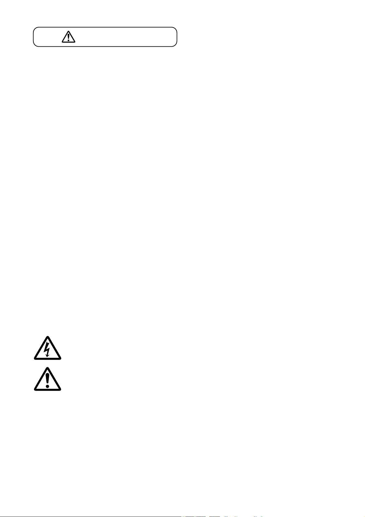
The lighting flash with arrowhead symbol, within an equilateral triangle, is intended to alert the user
to the presence of uninsulated "dangerous voltage" within the product's enclosure that may be of
sufficient magnitude to constitute a risk of electric shock to persons.
The exclamation point within an equilateral triangle is intended to alert the user to the presence of
important operation and maintenance (servicing) instruction in the literature accompanying the
appliance.
CAUTION
Page 6

6
3. GENERAL DESCRIPTION
The M-633D is a stereo mixer with digital signal processing functions such as Automatic Resonance Control
function (ARC), Feedback Suppressor function (FBS), Automatic Clipguard function (ACG), and Automatic
Mute function (AUTO MUTE).
It can be mounted in an EIA component rack (1U size*).
* 1U size = 44.5 mm (standard size)
4. FEATURES
• A stereo mixer equipped with 12 input channels (6 monaural inputs and 3 stereo inputs), and 6 output
channels (2 monaural outputs, 1 stereo output, and 1 stereo recording output).
• Assignable each input signal to 3 output channels individually (MONO OUT 1, MONO OUT 2, and STEREO
OUT).
• Sound reproduction owing to automatic clarity control (ARC function).
• Automatic feedback suppressor (FBS function).
• Automatic input sensitivity control when an excessive input signal is applied to the monaural input (ACG
function).
• Stereo input muted automatically by detecting the monaural input signal (Automatic Mute function).
• Input sensitivity switchable to either –10 dB or –46 dB for the monaural inputs.
• The monaural inputs capable of supplying phantom power (+24 V, 10 mA).
• Assignment switch cover for protecting the assigned setting positions of each input usable as a signal name
writing plate.
• Easy function settings using the front and rear panel controls.
5. HANDLING PRECAUTIONS
• The supplied power supply cord is designed for exclusive use with this unit. Never use it with other
equipment.
• Install the unit in locations where the temperature is between 0 and 40 °C (32 and 104 °F) and the moisture
is less than 90% (no dew condensation must be formed).
• The M-633D is a precision audio component. To prevent failure, avoid locations where the unit may be
exposed to strong shocks or vibrations.
• To clean, be sure to first switch off the unit's power, then wipe with a dry cloth. When the unit gets very dirty,
use a cloth damped in a neutral cleanser. Never use benzene, thinner, alcohol, or chemically-treated
cleaning cloth because such volatile liquids could deform or discolor the unit.
Page 7
7
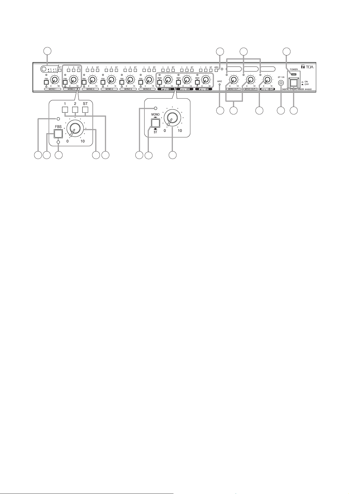
6. NOMENCLATURE AND FUNCTIONS
[Front]
1. Power switch
Press this switch to turn on the power. To turn off
the power, press this switch again.
2. Power indicator
Lights green when the power is switched on.
3. Assignment switch cover
A cover for protecting the setting positions of the
Assignment switches (16) and ARC switch (4). It
can be used as a writing plate.
4. ARC switch
Press this switch to enable the Automatic
Resonance Control function (ARC).
Hold down this switch for 3 seconds to start the
ARC measurement. Release the switch when the
ARC operation indicator (8) begins to flash. (See
p. 13.) Use a fine-tipped screwdriver to press in
the switch.
5. Output level indicators
Light green when the output sound level is
appropriate.
Light red when the output signal reaches 6 dB
below clipping level.
Light orange when the ARC switch is pressed if
the ARC filter has been previously set.
6. Summing output keys
Output the stereo input signals of each channel to
the stereo "L" and "R" outputs (17) in stereo mode
when not pressed and in monaural mode
(summing output) when pressed. (See p. 10.)
7. Stereo input level control knobs
Adjust the stereo input levels.
8. ARC operation indicator
Lights green when the ARC function is operating.
9. Monaural output level control knobs
Adjust the monaural output levels.
10. Stereo output level control knob
Adjusts the stereo output level.
11. Front-mounted stereo input jack
–10 dB*, 10 kΩ, unbalanced type.
Connect a stereo mini plug to this jack.
It is internally connected in parallel to the
STEREO IN 1 (24) on the rear panel. Adjust the
input level with the STEREO 1 input level control
knob (7).
* 0 dB = 1 V
12. Input level indicators
Light green when the output sound level is
appropriate.
Light red when the internal signal reaches 6 dB
below clipping level.
13. FBS keys
Press this switch to enable the Feedback
Suppression function (FBS).
Holding down the key for 1 second switches
between on and off states of the FBS function.
14. FBS operation indicators
Light green when the FBS function is operating.
15. Monaural input level control knobs
Adjust the monaural input levels.
16. Assignment switches
Used to select the output destination to which the
post-fader input signals of each input channel
are routed. (See p. 9.)
Press in an individual switch to set the
corresponding output destination as follows. To
release, press it in again.
1: MONO 1 output, 2: MONO 2 output,
ST: STEREO output.
Use a fine-tipped screwdriver to press in the
switch.
3
16151412 1213
6
4
5
98
10
7
11
2
1
Page 8
8
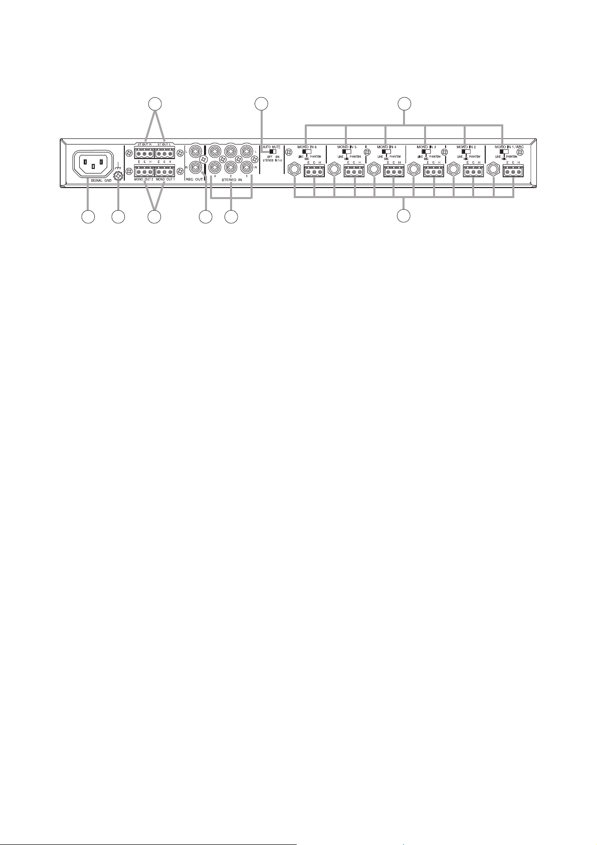
[Rear]
17. Stereo output terminals
0 dB*, 1 kΩ, electronically balanced type.
Use the supplied removable terminal plug for
connection.
18. Auto mute switch
Used to turn on and off the Automatic Mute
function (AUTO MUTE).
19. Input sensitivity selector switches
Used to select the input sensitivity and phantom
power ON/OFF.
Note
Set to "PHANTOM" only when connecting a
microphone which requires phantom power (+24
V, 10 mA) to the corresponding input terminal.
Connecting an equipment other than this type of
microphone to the input terminal set to
PHANTOM may cause the unit to malfunction or
may generate hum noise.
20. AC inlet
Connect this inlet to the AC wall outlet using the
supplied power cord.
21. Functional ground terminal
Hum noise may be generated when external
equipment is connected to the unit. Connecting
this terminal to the functional ground terminal of
the external equipment may reduce the hum
noise.
Note: This ground is not for protective ground.
22. Monaural output terminals
0 dB*, 1 kΩ, electronically balanced type.
Use the supplied removable terminal plug for
connection.
23. Recording output terminal
–10 dB*, 1 kΩ, unbalanced type.
Use an RCA plug for connection.
24. Stereo input terminals
–10 dB*, 10 kΩ, unbalanced type.
Use an RCA plug for connection.
STEREO IN1 is internally connected in parallel to
the front-mounted stereo input jack (11).
25. Monaural input terminals
Input level can be selected by the input level
selector switch (19) position as follows.
LINE: –10 dB*/2.4 kΩ
MIC: –46 dB*/2.4 kΩ
PHANTOM: –46 dB*/2.4 kΩ
Removable terminal blocks and phone jacks are
provided. Both terminals are electronically
balanced type and internally connected in
parallel.
* 0 dB = 1 V
17
20 21 22 23 24
18
19
25
Page 9
9
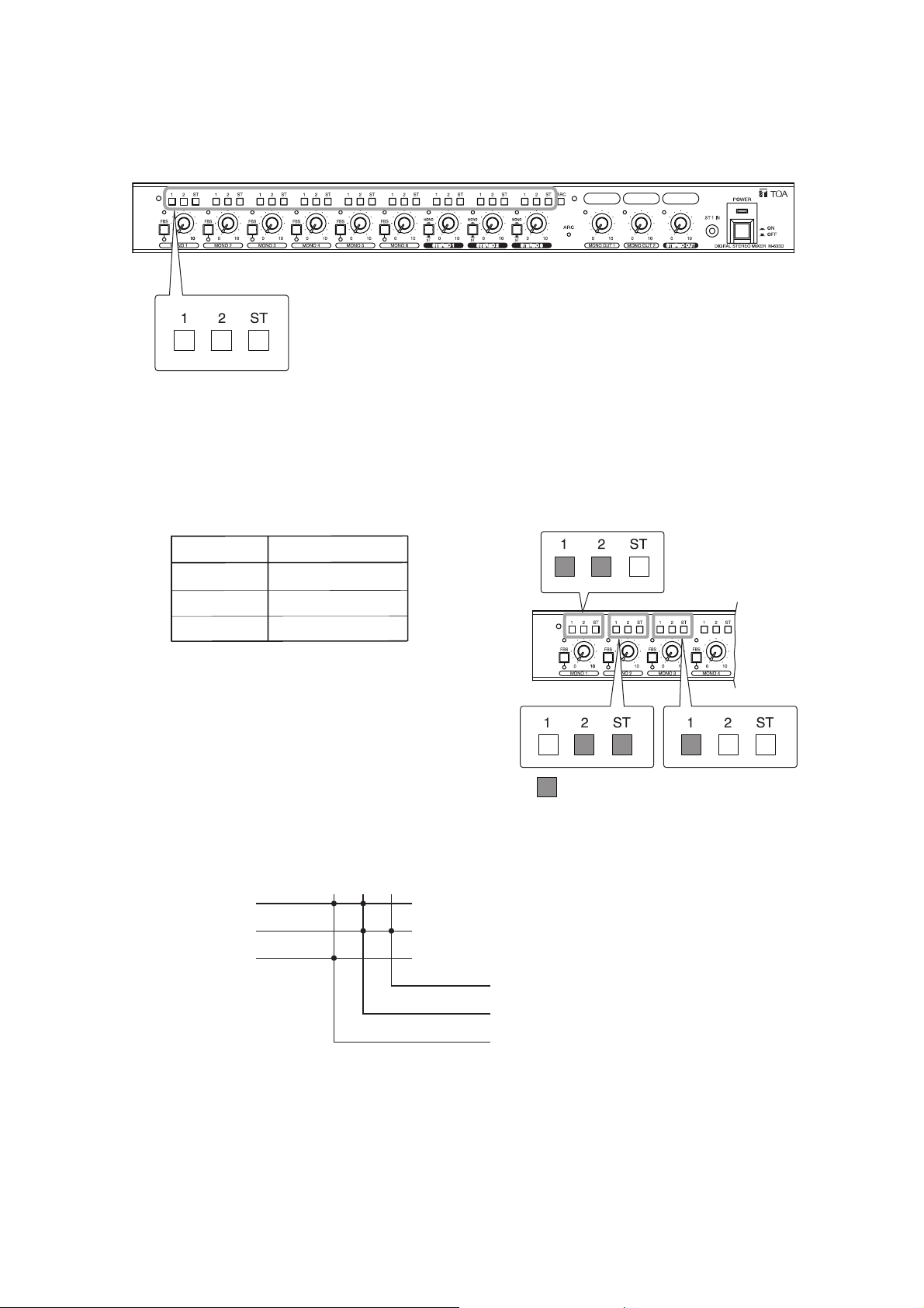
7. ASSIGNMENT SETTINGS
It is possible to assign each input to 3 output channels individually (MONO 1, MONO 2, and STEREO).
Pressing the Assignment switch "1" routes the input signal to the MONO OUT 1 output, switch "2" to the
MONO OUT 2 output, and switch "ST" to the STEREO OUT output.
Input signals assigned to the same output destination are mixed.
[Assignment setting example]
The figures below show an example of assignment settings of the inputs.
The figure below shows a signal flow.
Mixed signals of the MONO IN 1 and MONO IN 3 are output from the MONO OUT 1, those of the MONO IN 1
and MONO IN 2 from the MONO OUT 2, and the MONO IN 2 signal from the ST OUT L/R.
MONO 1
Input
MONO 1
MONO 2 2, ST
MONO 3 1
Input
MONO IN 1
MONO IN 2
MONO IN 3
Assignment switch
1, 2
Assignment switch
12ST
MONO 2
: Pressed-in state (ON)
Output
ST OUT L/R
MONO 3
MONO OUT 2
MONO OUT 1
Page 10
10
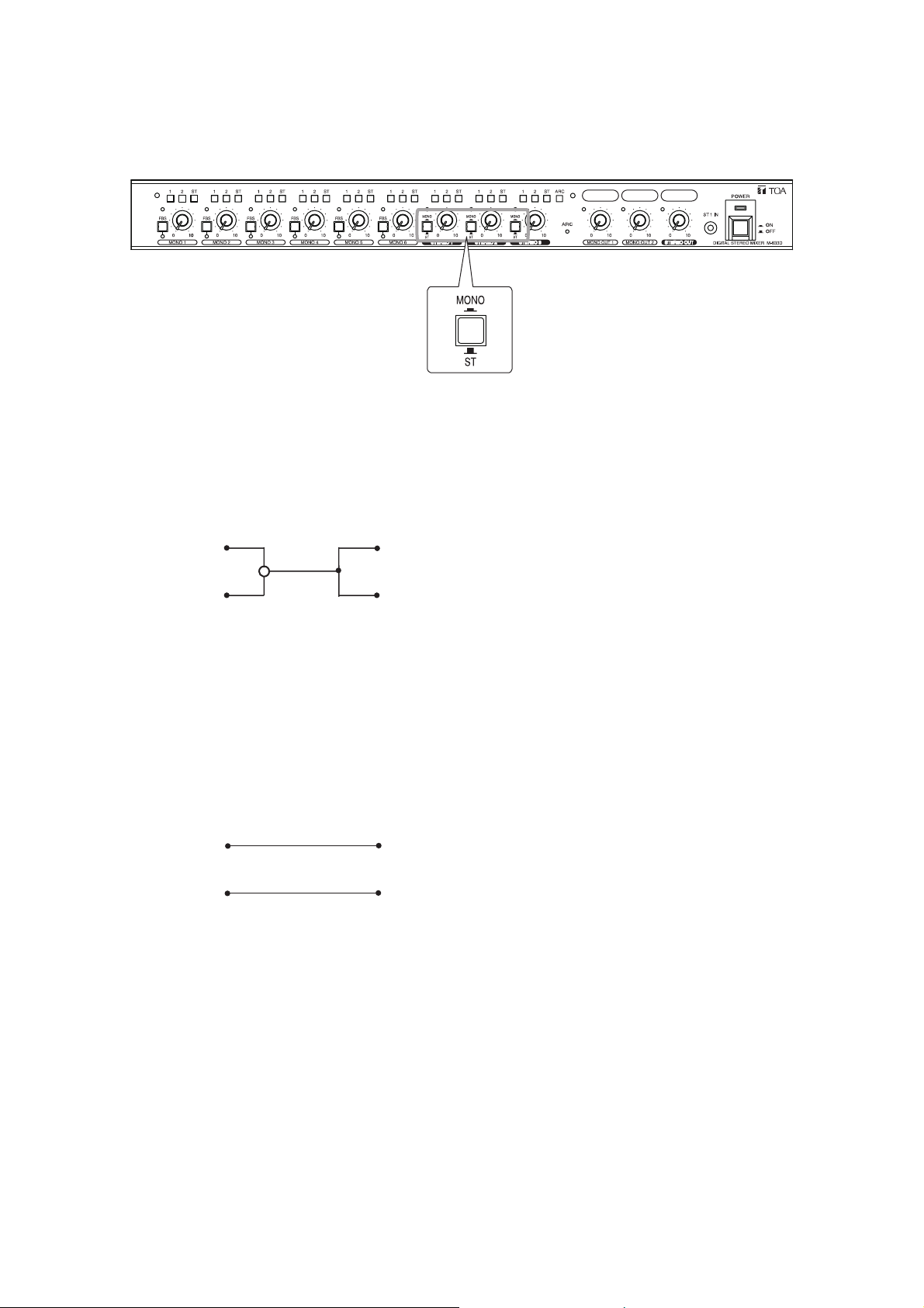
8. USING THE SUMMING OUTPUT KEYS
It is possible to output the stereo input signals applied to the STEREO 1 – 3 to the stereo "L" and "R" outputs
either in stereo mode or monaural mode.
[When the summing output key is not pressed in (ST position)]
The "L" channel’s input signal is output to the stereo "L" channel output, and the "R" channel’s input signal to
the stereo "R" channel output.
[When the summing output key is pressed in (MONO position)]
Signals applied to each of the input "L" and "R" channels are mixed and output to the stereo "L" and "R"
outputs.
Summing output key
L
Input Output
R
L
Input
R
L
R
L
Output
R
Page 11

11
9. SETTING THE ARC FUNCTION
9.1. What is the Automatic Resonance Control (ARC) Function?
It is a function that automatically creates a sound field compensation filter (ARC filter) to improve sound
clarity by measuring the inherent acoustic characteristics in architectural space.
9.2. Outline of the ARC Function Settings
The ARC function automatically creates an ARC filter, thereby reproducing highly clear output sound.
9.2.1. Enabling the ARC function (See p. 13 for details.)
Note
Before operating the ARC function, check that sound is actually output from the speakers after installation
and connection completion.
Select with the Assignment switches the output channel to which the ARC filter is to be set, hold down the
ARC switch for 3 seconds, then release it when the ARC operation indicator begins to flash.
The ARC measurement starts.
The ARC filter is set when the measurement has finished, enabling the ARC function. (The ARC operation
indicator lights.)
Note: To stop measurement partway, press the ARC switch again.
9.2.2. Disabling the ARC function (See p. 20 for details.)
Holding down the ARC switch for 8 seconds or more with all the 3 assignment switches of the MONO 1 in
OFF mode (unpressed state) causes the ARC operation indicator to flash. Then it goes off, disabling the
ARC function.
ARC
Hold down for
3 seconds.
ARC
Unlit
ARC
Release when the indicator
begins to flash.
ARC ARC
Flashing during
measurement
Measurement in progress
Lit
ARC
Measurement stops.
Press
ARC
Hold down for
8 second or more.
0 – 3 seconds After 8 seconds
ARC
Lit
3 – 8 seconds
ARC ARC
Flashing
ARC
Release when
the indicator goes off.
Unlit
Page 12

12
9.2.3. How to confirm the ARC enabled channel
The output level indicator of the ARC enabled (ARC filter preset) output channel lights orange when the ARC
switch is pressed.
9.2.5. ARC measurement procedure
9.2.4. ARC operation indicator status
Light orange.
ARC
Press briefly,
then release.
An example that the ARC filter is set to
the MONO OUT 1 and MONO OUT 2 channels.
ARC measurement
in progress
ARC ARC ARC
Make an initial setting of input and output levels.
Connect a measuring microphone*, then check if it works.
* The microphone for normal use can be used.
Set the output channel and output level.
ARC filter ON ARC filter OFF
LitFlashing
(See Step 1 on p. 13.)
(See Steps 2 and 3 on p. 14.)
(See Steps 4 and 5 on p. 15.)
Unlit
Install the microphone.
Conduct ARC measurement.
ARC function is enabled.
(See Step 6 on p. 16.)
(See Step 7 on p. 17.)
Page 13

13
9.3. Enabling the ARC Function
Notes
• The ARC filter is created on the output channel selected with the Assignment switches at the ARC
measurement.
• The ARC filter previously set on the output channel will be updated by the newly created ARC filter after the
ARC measurement.
• To initialize the ARC filter, disable the ARC function. (See p. 20.)
The ARC filters for all the output channels are initialized. They cannot be initialized individually.
• Use a fine-tipped screwdriver to press in the Assignment and ARC switches.
Step 1. Make an initial setting of the input and output levels.
1-1. Turn all the output level control knobs to the "0" position.
1-2. Turn the MONO 1 input level control knob to the 12 o'clock position.
1-3. Fully turn down the output volume of the connected amplifier.
1
-2
1
-1
Page 14

14
Step 2. Connect a measuring microphone.
The microphone for normal use can be used.
2-1. Connect the microphone to the phone jack or removable
terminal block of MONO IN 1/ARC on the rear panel.
2-2. Set the input sensitivity selector switch to the appropriate
position depending on the microphone to be connected.
Dynamic microphone: MIC
Phantom powered condenser microphone: PHANTOM
Wireless tuner output (Line level): LINE
Step 3. Check to see if the microphone works correctly.
3-1. Speak into the microphone.
Confirm that the MONO 1’s input level indicator lights green.
Notes
• Hold the microphone about 7 cm (3") from the mouth. Speak at a normal voice level.
• Sound is not output from the speakers at this stage as the unit's output level control knobs are
turned fully counterclockwise.
3-2. Check to see the following settings if the input level indicator does not light green.
Input signal is too small.
• Check that the microphone switch is turned ON.
• Check that the rear-mounted input sensitivity selector switch is placed in the correct position for the
microphone.
2
-2
2
-1
Input level indicator (lit green)
When the indicator does not light
When a dynamic
microphone is used
When a condenser
microphone is used
Page 15

15
Input signal is too big.
• Check the position of the input sensitivity selector switch on the unit's rear panel.
Try to set the switch to "LINE."
When the indicator lights red
Step 4. Select the output channel.
Press in the MONO 1’s assignment switch corresponding to the output channel to which the
ARC filter is set.
Step 5. Set the output volume level.
5-1. Turn the output level control knob corresponding to the assignment switch selected in Step 4
to the 12 o'clock position. (Setting example of MONO OUT 1)
5-2. Adjust the power amplifier's volume level.
Speaking into the connected measuring microphone, adjust the volume to the level normally
used with the volume control knob of the amplifier connected to the unit.
4
5
-1
Page 16

16
Step 6. Install the measuring microphone.
It is recommended to install the microphone as shown below as a guide.
[Microphone setting example]
Height of the microphone: At the listening position
Angle of the microphone: 45 º up
Location of the microphone: About the center of the room
(See the figure below.)
Direction of the microphone: Point to the speaker. (See the figure below.)
[Microphone setting example]
School room: Point to a platform.
Gymnasium and multipurpose auditorium: Point to the center of the stage.
Conference room: Point to the chairperson.
45°
Location of the microphone: About the center of the room
Page 17

17
Step 7. Conduct ARC measurement.
Notes
• To stop measurement partway, press the ARC switch.
• Never operate the switches and knobs of the unit and the external equipment during the ARC measurement.
[ARC measurement operation]
A 3-stage operation shown on the next page is performed during the ARC measurement.
Different tones sound in each operation stage.
The ARC operation indicator flashes slowly during normal measurement, but it begins to flash rapidly when a
failure occurs.
Hold down the ARC switch for 3 seconds.
The ARC operation indicator begins to flash and the measurement starts.
ARC Switch
ARC operation indicator
ARC
Hold down for
3 seconds.
ARC
Unlit
ARC
Release when the indicator
begins to flash.
ARC
Flashes during
the measurement.
Measurement in progress
ARC
Measurement stops.
Press
ARC operation indicator status
Measurement progresses normally
ARC
Flashing slowly
A failure occurs
ARC
Flashing rapidly
Page 18

18
Measurement starts.
Measurement is complete, and the ARC filter is set.
The output level indicator of the ARC enabled output channel flashes orange for 1 second.
In this case, the ARC operation indicator changes from flashing to steady on (green). The ARC filter data is
automatically saved, and remains effective even after power is cycled.
Note
After measurement completion, move the microphone to your desired location.
The signals input to the MONO 2 – 6, and STEREO 1 – 3 are muted during
measurement. (Only MONO 1's signal is output.)
The FBS function and Automatic mute function are temporarily turned OFF.
When the ARC operation indicator flashes rapidly
soon after measurement starts.*
MONO 1 is not assigned to any output.
Check the assignment setting. (See Step 4 on p. 15.)
Volume adjustment: Specific tone sounds twice.
When the ARC operation indicator flashes rapidly*
Input level is too small.
• Speak into the microphone, and check that voice is output from the
speaker.
• Increase the input level by turning the MONO 1's input level control
knob clockwise.
Distance measurement: Specific tone sounds twice.
When the ARC operation indicator flashes rapidly*
Large noise is detected.
Adjust the microphone direction. Also, check the presence of large
ambient noise.
Sound field measurement: Specific tone sounds 3 times.
* Perform the following reset operation if these errors occurred.
1. Stop the measurement by pressing the ARC switch.
Measurement is complete.
The ARC indicator stops flashing, then goes off or lights steady.
2. Remedy the cause of the failure, then restart the ARC
measurement in Step 7.
Output level indicator
*1 The indicator may light green depending on the input level
of the microphone.
2
*
1
Unlit *
ARC operation indicator
Flashing orange
for 1 second. *
2
The output level indicator of the channel where the ARC
filter has already been set flashes orange even when this
channel was not assigned at the time of ARC measurement.
ARC ARC
Flashing
Lit green
Page 19

19
9.4. Making Fine Acoustic Adjustment
When finer acoustic adjustment is required, different ARC filters can be set for individual output channels.
[Setting example in a gymnasium where the unit's output channels are assigned as follows]
Set different ARC filters to the MONO OUT 1 channel and STEREO OUT channel.
1-1. Turn the MONO 1's input level control knob to the 12
o'clock position.
1-2. Press in only the MONO 1’s Assignment switch "1" to
turn it ON.
1: ON
2: OFF
ST: OFF
1-3. Turn the MONO 1's output level control knob to the 12
o'clock position.
1-4. Adjust the volume level of the output amplifier
connected to the MONO OUT 1.
1-5. Conduct ARC measurement. (See Step 7 on p. 17.)
The ARC filter is assigned to the MONO OUT 1 channel.
Cable wiring example
• MONO OUT 1 channel: Ceiling speakers
• MONO OUT 2 channel: No connection
• STEREO OUT channel: Stereo speakers installed at
both sides of the stage
Step 1. Set the ARC filter only to the MONO OUT 1 channel (ceiling speakers).
STEREO OUT channel
MONO OUT 1 channel
1
-2
Press in (ON).
1
-3
Page 20

20
Step 2. Set ARC filter only to the STEREO OUT channel (Stereo speakers installed at both sides of the
stage).
2-1. Press in only the MONO 1’s assignment switch "ST" to turn it ON.
1: OFF
2: OFF
ST: ON
2-2. Turn the output level control knobs as follows.
MONO OUT 1: To the "0" position
STEREO OUT 2: To the 12 o'clock position.
2-3. Adjust the volume level of the output amplifier connected to the
STEREO OUT.
2-4. Conduct ARC measurement. (See Step 7 on p. 17.)
The ARC filter is assigned to the STEREO OUT channel.
Different ARC filter settings are complete to each output of the MONO OUT 1 channel and STEREO OUT
channel.
The ARC filter data is automatically saved, and remains effective even after power is cycled.
9.5. Disabling the ARC Function
Step 1. Place the MONO 1’s all 3 assignment
switches in unpressed state.
Step 2. Hold down the ARC switch for 8
seconds.
The ARC operation indicator flashes
rapidly after 3 seconds.
Continue to hold it down for 5 seconds.
The ARC operation indicator goes off,
disabling the ARC function.
2
2
-1
Press in (ON).
-2
1
ARC
Hold down for
8 seconds.
0 – 3 seconds After 8 seconds
ARC
Lit
2
ARC
3 – 8 seconds
ARC ARC
Flashing
Release when
it goes off.
Unlit
Page 21

21
10. SETTING THE FBS FUNCTION
10.1. What is the Feedback Suppressor Function (FBS)?
It is a function that the built-in feedback suppressor filter automatically works to suppress acoustic feedback
when the feedback occurs.
10.2. Setting the FBS Function
If acoustic feedback occurs when the FBS function is enabled, the feedback suppressor filter automatically
operates to suppress the feedback.
The FBS function assigned to each of the MONO 1 – 6 channels can operate independently.
10.2.1. Enabling the FBS function
Hold down the FBS key for 1 second or more when the FBS operation indicator remains unlit.
The FBS operation indicator will light, and the FBS function is enabled.
Notes
• Feedback may not be suppressed as the case may be. In this case, decrease the corresponding channel’s
monaural input level by turning the control knob counterclockwise.
• Feedback suppressor filter settings are not stored. The setting data is initialized when the power is turned
off. However, the FBS function enabled or disabled status is stored.
10.2.2. Disabling the FBS function
Disabling the FBS function causes the feedback suppressor filter to be initialized.
Hold down the FBS key for 1 second or more while the FBS operation indicator is lighting.
The indicator goes off, and the FBS function is disabled.
Level
Feedback suppressor
filter
Feedback
frequency
Frequency
Hold down for over 1 second,
then release when the indicator
lights.
Lit
Lit
Hold down for over
1 second, then
release when the
indicator goes off.
Unlit
Page 22

22
11. SETTING THE AUTOMATIC MUTE FUNCTION
11.1. What is the Automatic Mute Function (AUTO MUTE)?
It is a function that attenuates the signal input to the STEREO 1 through 3 by detecting signals input to the
MONO 1 – 6.
AUTO MUTE is also called as Ducker.
This function helps to have paging announcements heard distinctly by attenuating the BGM volume when
initiating the announcement during BGM broadcast.
Tip
A release time is the period of time from the announcement end to the stereo signal mute release start.
11.2. Setting the Automatic Mute Function
Use the rear-mounted AUTO MUTE switch to set the Automatic Mute function.
Shifting the AUTO MUTE switch to the ON position turns on the AUTO MUTE function. Shifting it to the OFF
position turns off the AUTO MUTE function.
Tip
The input level indicators of the STEREO 1 – 3 light orange while these signals are being attenuated.
The attenuation level is 30 dB.
Level
–∞ dB
Stereo input signal
Mute
30 dB
level
Monaural input signal
Announcement
starts.
About 2 seconds
Relesse time
Announcement
ends.
Time
Page 23

23
12. AUTOMATIC CLIPGUARD (ACG) FUNCTION
It is a function that automatically control input sensitivity to an appropriate value when the broadcast is
distorted in the presence of an excessive input signal.
For example, the ACG function prevents the broadcast from being made with its sound distorted even if a line
level signal is erroneously applied to the MONO IN input set to "MIC."
The ACG function operates on each channel with the input sensitivity selector switch placed in "MIC" or
"PHANTOM" position.
Notes
• If the ACG function works, something is wrong with connection. Make cable connection correctly after an
announcement is complete.
• Distorted sound is output from the unit for several seconds in order to detect distortion, however, this is not a
failure.
Page 24

24
14. INSTALLATION
14.1. Mounting in a Rack
Mount the unit in an equipment rack using the supplied rack mounting screws.
Step1. Attach the rack mounting brackets to the unit's sides.
Step2. Mount the unit in a rack.
13. RESETTING TO FACTORY DEFAULT SETTINGS
Step 1. Disable the ARC function. (See p. 20.)
Step 2. Disable the FBS function. (See p. 21.)
Step 3. Turns off the Automatic mute function.
Shift the rear-mounted AUTO MUTE switch to the OFF position.
Step 4. Disable the ACG function
Shift all the Input sensitivity selector switches of the rear-mounted MONO IN 1 – 6 to the "LINE"
position.
The settings are returned to the factory default settings.
34
M-633D
Rack mouting bracket
(supplied)
Machine screw M3 x 8
(supplied)
1
2
Rack mouting screw 5 x 12 with washer
(supplied*)
* Not supplied with the unit of US version (M-633D CU).
Page 25

25
When installing the unit in an equipment rack, do not to block the ventilation slots on the unit's sides
and rear. Doing so may cause heat to build up inside the unit and result in fire.
CAUTION
14.2. Mounting on a Desk
When installing the unit on a desk, attach the supplied rubber feet to the unit's bottom surface.
Rack
Power amplifier
Blank panel
M-633D
Rubber foot (supplied)
M-633D bottom surface
Page 26

26
15. CONNECTION
15.1. Connection Example
DIGITAL POWER AMPLIFIER DA-250F
DOWN
15.2. Phantom Power Supply
• Set the rear-mounted Input level selector switch to "PHANTOM" position only when connecting a
microphone which requires phantom power (+24 V, 10 mA) to the corresponding input terminal. Connecting
an equipment other than this type of microphone to the input terminal set to PHANTOM may cause the unit
to malfunction or may generate hum noise.
• Phantom power is not supplied to the phone jacks (MONO IN 1 – 6).
M-633D
Power amplifier
Playback devices (such as cassette deck,
CD player, or MD player)
Wireless equipment
Microphones
DOWN
Speakers
Speakers
Page 27

27
[Connector connections]
Step 1. Loosen the terminal screw, then insert the cable.
Step 2. Retighten the terminal screw. (Pull on the cable to
ensure it is securely connected.)
Step 3. Insert the removable terminal plug into the
input/output terminal block on the unit's
rear panel.
Tip
Recommended slotted screwdriver type: Screwdriver with blade that is 3 mm (0.12") in width
15.3. Removable Terminal Plug Connection
Notes
• Be sure to use shielded cables for audio signal lines.
• Avoid soldering cable conductor, as contact resistance may increase when the cable is tightened and the
solder is crushed, possibly resulting in an excessive rise in joint temperatures.
[Cable end treatment]
Shielded cable
7 mm (0.28”)
20 mm
(0.79”)
2
Earth
Tightens
1
Hot
Cold
Shielded cable
Slotted screwdriver
Loosens
Terminal screw
Removable terminal plug
1
Bit width 3 mm (0.12”)
Page 28

28
16. BLOCK DIAGRAM
LINE (−10 dB)
MIC (−46 dB)
PHANTOM (−46 dB)
HA
HA
HA
HA
HA
HA
EBA
EBA
EBA
EBA
EBA
EBA
LINE
MIC
PHANTOM
LINE
MIC
PHANTOM
LINE
MIC
PHANTOM
LINE
MIC
PHANTOM
LINE
MIC
PHANTOM
HA
HA
HA
HA
HA
HA
Analog
Digital
ST
1
2
ST
1
2
ST
1
2
ST
1
2
ST
1
2
ST
1
2
ST
1
1
2
ST
2
ST/MONO
ST/MONO
ST
1
1
2
ST
2
ST/MONO
ST/MONO
ST
1
1
2
ST
2
ST/MONO
ST/MONO
FBS
FBS
FBS
FBS
FBS
FBS
A/D
A/D
A/D
A/D
A/D
A/D
A/D
A/D
A/D
A/D
A/D
A/D
MONO IN 1
MONO IN 2
MONO IN 3
MONO IN 4
MONO IN 5
MONO IN 6
STEREO IN 1
STEREO IN 2
STEREO IN 3
Clipping level (+12 dB)
LINE (−10 dB)
The input level indicator lights red (+6 dB).
MIC (−46 dB)
L
R
L
R
L
R
(FRONT)
−10/−46 dB
−10/−46 dB
−10/−46 dB
−10/−46 dB
−10/−46 dB
−10/−46 dB
−10 dB
−10 dB
−10 dB
+20
+10
0
−10
−20
−30
−40
−50
−60
[dB]
SIGNAL
GREEN RED
VOLUME
AUTO CLIP GUARD
+24 V
PHANTOM
POWER
+24 V
PHANTOM
POWER
+24 V
PHANTOM
POWER
+24 V
PHANTOM
POWER
+24 V
PHANTOM
POWER
+24 V
PHANTOM
POWER
AUTO MUTE
Page 29

29
LR12
Analog
LA
LA
LA
LA
LA
LA
ARC
ARC
ARC
ARC
D/A
D/A
D/A
D/A
D/A
D/A
REC OUT (–10 dB)
STEREO (0 dB)
LINE (0 dB)
0 dB = 1 V
MONO OUT 1
MONO OUT 2
ST OUT L
ST OUT R
REC OUT L
REC OUT R
[dB]
+20
+10
0
−10
−20
−30
−40
−50
−60
−10 dB
−10 dB
0 dB
0 dB
0 dB
0 dB
RED
GREEN
BUS
STEREO MONO
SIGNAL
VOLUME
Page 30

30
17. DIMENSIONAL DIAGRAM
[Rear]
[Front]
483.6 (19.04)
466 (18.35)
420 (16.54)
Unit : mm (in)
(1.25)
31.8
(1.73)
(1.84)
44
46.8
[Side]
20 (0.79) 20 (0.79)
22 (0.87)
341.3 (13.44)
320 (12.6)
6
-
M3
Page 31

31
18. SPECIFICATIONS
Model No.
Power Source
Power Consumption 13 W 14 W 14 W 14 W 13 W
Frequency Response 20 Hz – 20 kHz
Sampling Frequency 48 kHz
Dynamic Range Over 90 dB (IHF–A weighted)
Distortion Under 0.03%, 1 kHz, –10 dB* input, 0 dB* output (20 Hz – 20 kHz, BPF)
Input 6 monaural input channels (MONO IN 1 – 6), selectable independently from 3
types of inputs below for each channel
LINE: –10 dB*, 2.4 kΩ, electronically balanced
MIC: –46 dB*, 2.4 kΩ, electronically balanced
PHANTOM: –46 dB*, 2.4 kΩ, supplies phantom power of +24 V DC, 10 mA,
electronically balanced
Removable terminal block (3P), phone jack
3 stereo inputs (L, R) (STEREO IN 1 – 3)
: –10 dB*/10 kΩ, RCA jack (STEREO IN 1 – 3), Stereo mini jack (ST IN 1)
Output 2 monaural output channels (MONO OUT 1, 2)
: 0 dB* (applicable load: over 1 kΩ), electronically balanced, removable
terminal block (3P)
1 stereo output (L, R) channel (ST OUT L, R)
: 0 dB* (applicable load: over 1 kΩ), electronically balanced, removable
terminal block (3P)
1 stereo recording output (L, R) channel (REC OUT L, R)
: –10 dB* (applicable load: over 1 kΩ), RCA jack
Bus Line Monaural channel x 2, Stereo channel x 1
AD Converter 24 bits
DA Converter 24 bits
Signal Processing
Automatic Resonance 3 output channels (each monaural output channel, stereo output L, R),
Control Function (ARC) independent settings for each channel, automatic creation of EQ curves
(for sound field compensation)
ARC measurement start switch x 1, Function ON/OFF check indicator x 1
Feedback Suppression 6 channels (each monaural input channel), independent settings for each
Function (FBS) channel
Function ON/OFF switch x 6
Function ON/OFF check indicator x 6
Automatic Clipguard 6 channels (each monaural input channel), independent operation for each
Function (ACG) channel
Automatic Mute Function ON/OFF switch x 1
Function (AUTO MUTE)
Input Level Indicator 2-color LED indicator: Green (for appropriate level)/red (for peak level)
Output Level Indicator 2-color LED indicator: Green (for appropriate level)/red (for peak level)
Operating Temperature 0 to 40 °C (32 to 104 °F)
Operating Humidity
Under 90% RH (no condensation)
Finish Panel: Aluminum, black, hair-line
Case: Precoated steel sheet, black, 30% gloss
Dimensions 420 (w) x 44 (h) x 341.3 (d) mm (16.54" x 1.73" x 13.44")
Weight 4.0 kg (8.82 lb)
* 0 dB = 1 V
Note: The design and specifications are subject to change without notice for improvement.
M-633D
CU
M-633D
CE, CE-GB
M-633D
CE-AU, CN
M-633D
KR
M-633D
TW
120 V AC
60 Hz
220 – 240 V AC
50/60 Hz
220 – 240 V AC
50 Hz
220 V AC
60 Hz
100 – 120 V AC
60 Hz
Page 32

133-22-273-5A
URL: http://www.toa.jp/
Traceability Information for Europe (EMC directive 2004/108/EC)
Manufacturer:
TOA Corporation
7-2-1, Minatojima Nakamachi, Chuo-ku, Kobe, Hyogo,
Japan
Authorized representative:
TOA Electronics Europe GmbH
Suederstrasse 282, 20537 Hamburg,
Germany
FCC REQUIREMENTS
Note
This equipment has been tested and found to comply with the limits for a Class A digital device, pursuant
to Part 15 of the FCC Rules. These limits are designed to provide reasonable protection against harmful
interference when the equipment is operated in a commercial environment. This equipment generates,
uses, and can radiate radio frequency energy and, if not installed and used in accordance with the
instruction manual, may cause harmful interference to radio communications.
Operation of this equipment in a residential area is likely to cause harmful interference in which case the
user will be required to correct the interference at his own expense.
Modifications
Any modifications made to this device that are not approved by TOA Corporation may void the authority
granted to the user by the FCC to operate this equipment.
This Class A digital apparatus complies with Canadian ICES-003.
Cet appareil numérique de la classe A est conforme à la norme NMB-003 du Canada.
• Accessories
Power cord (2 m or 6.56 ft) ........................ 1
Removable terminal plug (3P) .................. 10
Rubber foot ................................................ 4
Rack mounting bracket .............................. 2
Rack mounting screw 5 x 12 ...................... 4
Machine screw M3 x 8* .............................. 6
* Not supplied with the unit of US version (M-633D CU)
 Loading...