

Page 1
Operating Instruction Manual
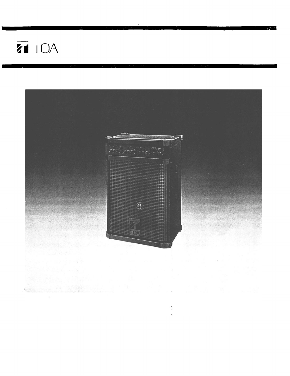
ELECTRONIC MUSIC AMPLIFICATION SYSTEM
Model KD-3
TOA Corporation
KOBE, JAPAN
Page 2
Contents
Precautions
General Description
Features
Front Panel: Names of components & their usage
Rear Panel: Names of components & their usage
Block and Level Diagrams
Specifications
Appearance ...
Precautions
1
2
2
3
4
5
5~6
6
1. Power Supply
The KD-3 is designed to operate on local AC (50/60Hz) Mains, ±10%.
2. XLR Type Audio Connector
The connectors are wired as follows.
The pin 1 is ground (shield), the pin 2 cold (low, minus), the pin 3 hot (high, plus).
3. Phantom Power Supply
The phantom power switch on channel 1 input permits the user to supply 48V DC
through the input connector to a condenser microphone. If phantom power is not
required, the switch must be in the "off' position.
4. Description of components and functions of the KD-3
Various descriptions are applied, depending on each manufacturer. In our
Operating and Instruction. Manual explanation of components and functions is
made according to TOA's usage for them.
— 1 —
Page 3

General Description
The TOA KD-3 is a complete electronic music amplification system in a single
portable package, consisting of a stereo mixer, spring reverberation unit, graphic
equalizer, power amplifier, and two-way speaker system.
The mixer section provides four input channels. Each input features 2-band active EQ,
an independent effects send, a clip LED indicator, a direct output, and a channel level
control with concentric balance control. Channel 1 features an electronically balanced
XLR mic input connector with switchable 48 volt phantom power, for use with
condenser-type microphones, and each input channel features input sensitivity
switches. In addition, channel four features an RIAA equalized phono input for direct
connection of magnetic cartridge turntables.
The master section contains an effects patching loop with crossfade and level controls,
5-band EQ stereo L&R controls, and a stereo headphone monitoring system.
The 220 watt RMS internal power amplifier features Auto Comp compression
circuitry, with an LED indicator, to ensure distortion-free performance and protection
for the internal speaker system. The two-way speaker system utilizes a heavy duty
15-inch woofer and a constant directivity horn with piezo electric driver.
The KD-3 is covered in a durable and attractive high tech gray vinyl fabric.
Features
System Features
Four input channels
•
220 watts/4-ohm, 150 watts/8-ohm power amplifier output
•
Auto Comp compression circuitry w/indicator
•
Power amplifier protection circuitry w/indicator
•
Built-in, heavy-duty two-way loudspeaker system of 15"(38cm) woofer and constant
•
directivity horn with piezo driver
Built-in spring reverberation unit
•
MIDI Thru circuitry
•
Each Input Channel
Two band EQ
•
Independent effect send is post-EQ/post-fader
•
Direct output on each channel, ideal for recording
•
Concentric balance control and channel volume control
•
LED clip indicator for best signal to noise ratio
•
Individual Input Level Selector switches
•
Input Channel 1 has electronically balanced XLR microphone input connector with
•
switchable 48 volt phantom power
Input Channel 4 has stereo phono (RIAA) inputs for turntable with magnetic
•
cartridge
Master Section
Stereo Left and Right outputs with both RCA and 1/4" phone jacks
•
Level and crossfade control for returning effects signals to stereo mixing busses
•
Two band EQ for internal reverberation unit
•
Headphone monitoring for Stereo L and R, SUM and EFF
•
Five band graphic equalizer w/bypass switch
•
Complete patch bay
•
— 2 —
Page 4

Effect Control [EFF]
This control determines the
amount of post-fader/post-EQ signal assigned to t he effect buss
from a given input channel, and
thus the level of effects for that
channel.
Clip LED Indicator [CLIP]
The LED indicator lights when
the pre or post EQ signal level
reaches 3dB below clipping, giving a visual reference for optimum setting of the level control.
Under normal usage, the cl ip
LED's should only flash intermittently. A constant or steady LED
indicates that t he input level control setting is too high, and
should be reduced.
Low Equalizer Control [LOW]
The low EQ control alters the low
frequency response of th e input
channel, providing ±15dB at
20Hz of continuously variable active shelving equalization. The
"0" detented position provides
flat audio response. Please no te
that excessive boosting of low
frequencies may cause th e input
clip LED to light. Under these
circumstances, it may be necessary to lower the input level
control in order to maintain proper headroom an d minimize distortion.
High Equalizer Control [HIGH]
The hig h EQ control alters t he
high frequency response of the
input channel, providing ±15dB
at 20kHz of continuously variable
active shelving equalization. The
"0" detented position provides
flat audio response.
Balance Control [BAL]
This control adjusts the level balance of the channel input signal
fed to the Stereo Left and Right
mixi ng busses.
Input Channel Level [LEVEL]
The level control provides continuously variable adjustment of
the channel output to the Stereo
Left and Right mixing busses,
thus d etermin ing the level of the
channel in the main sound system mix. The nominal level of the
input level control is at the "0"
dB position.
Graphic Equalizer In/Out Switc h
[IN/OUT ]
The in/out switch enables comparison between a flat response
(OUT) an d th e equalized response (IN ). The "out" position
completely removes the equalizer
from the KD-3 circuitry.
Graphic Equalizer Control
[GRAPHIC EQUALIZATION]
The graphic equalizer is 5 independent active bands (filter), providing 15dB of boost or cu t at
each center frequency. The "0"
detented position provides flat
audio response.
Internal Reverb Equalizer-
Control [REV EQ HIGH/LOW]
These controls alter the frequency
response of the b uilt-in reverb
circuitry. The "0" detented position of both controls provide flat
audio response.
Cross-fade Control fo r Reverb
and Effect [REV/EFF X-FD]
When this control is in the center
position, the reverb signal (thus
the internal reverberation unit)
and EFF RET signals are equally
assigned t o th e Stereo m ixing
buss. Rotating the control
counter-clockwise decreases t he
EFF RET signal level, keeping the
original level of the reverb signal.
Rotating the control clockwise
decreases the reverb signal level,
keeping the original level of the
EFF RET signal.
Level Control for Reverb/Effec t
[REV/EFF LEVEL]
This control governs the amount
of reverb signal through the reverberation unit (built in), and effect
signal returned through the effect
return jack (EFF RET) to the
stereo mixing buss. The signals of
reverb signal and EFF RET are
controlled simultaneously.
System Level Control
[SYSTEM LEVEL]
This control determines the overall level of the KD-3 system.
Stereo Level Control
[STEREO LEVEL]
These concentric controls determine the overall level of the
Stereo Left and Right output
(STEREO OUT L, R).
Aux Input Level Control
[AUXIN]
These concentric controls govern
the amount of Aux signals to
Stereo Left an d Right through the
Aux In jacks (AUX IN L, R).
Headphone Selector, Leve l
Control, and Ja ck [PHONES)
An outpu t jack, level control, and
3-position rotary switch are provided for the use of headphones.
Any one of three signals can be
monitored through headphones
using the selector switch:
STEREO, SUM, or EFF. Al l monitored signals are in mono with the
exception of Stereo Left and Ri ght
which are monitored, of course,
in stereo. The level control adjusts the volume of the headphones, and the headphone jack
will accept a ny stereo headphones with an impedance of 8
ohms or higher.
Clip LED Indicator [CLIP]
The Stereo and Sum cli p indicators light when their respective
signals reach 3dB below clipping,
giving a visual indication before
the onset of distortion.
Sum Pro/Post Select Switc h
[SUM SELECT]
The mono Sum (System) signal is
derived by summing the Stereo
Left and Ri ght signals. The Su m
Select switch determines whether
this summing occurs before or
after the Master Stereo faders.
When using the switch in the
Pre-position, the Sum (System)
outp ut level is indep endent of the
Master Stereo Le ft and Right level
controls. In the post-position, adjusting the Master Stereo Left and
Right level controls will affect the
volume of the Sum (System) out-
put.
Power/Protect LED
Indicato
r
[POWER/PROTECT]
The LED indicator lights red and
remains lit for 3 seconds after the
power switch has been turned on,
and then turns to green when the
KD-3 is powered up. The LED
lights red when the p rotection
circuit is activated.
Power Amp Compressio n
Indicator [COMP]
The Comp LE D l ights when th e
internal compressor is activated.
The compressor is provided to
protect t he speaker system by
compressing the input signal
level of the power amplifier when
clipping occurs in the output
stage. Frequent flashing of the
LED is not reason for alarm.
However, a constant or steady
light indicates that the KD-3 is
being overdriven and that the
internal power amplifier is poss-
ibly "under powered" for that
particular application. The out-
put level of the KD-3 should be
decreased unt il the LED only
flashes intermittently.
MIDI LED Indicator [MIDI IN]
This LED indicates the presence
of MIDI data at the MIDI input
connector on the rear panel (M-
IDI
IN).
Stereo L&R Output Jack
[STEREO OUT L/R)
The unbalanced RCA pin jacks
and 1/4" phone jacks are wired in
parallel. The RCA pi n jack has a
nominal output level of —l0 dB
and an impedance of 1k ohms,
and the 1/4" phone jack has a
nominal output level of +4dB
and an impedance of 1k ohms.
All jacks may be used simultaneously.
Graphic Equalizer Output Jack
[GEQ OUT]
This jack allows the KD-3 and the
internal graphic equalizer to be
used with an external power
amplifier, or in conjunction with
the GEQ in jack, to be used independently of all other KD-3 circuitry. Nominal output level is
+4dB with an impedance of 1k
ohms.
Power Amplifier Input Jack-
[POWER IN]
The Power Amp Input jack allows
the internal power amplifier to be
used with external equipment.
When a plug is inserted, the
power amplifier is automatically
disconnected from the KD-3 mixer section. The nominal input
level is +4dB with an input impedance of 10k ohms.
MIDI Input Connector [MIDI IN]
This connector w ill accept the
MIDI output of any synthesizer,
sequencer, or other M ID I device.
Use of non-MIDI-standard DIN
cables, or of cables longer tha n
5m (16ft.) may result in i mproper
operation and data loss.
AC Power Cord-
The power" cord is of the threewire type with proper grounding
facilities built-in. (6ft.)
Caution — The ground pin
should not be removed under any
circumstances. If the KD-3 m ust
be used without proper grounding facilities, a suitable grounding
adapter should be utilized. Operation of the KD-3 with proper
grounding techniques will result
in less system noise and greatly
reduced shock hazard.
Graphic Equalizer Input Jack
[GEQ
IN ]
The GEQ input jack allows the
graphic equalizer to be used independently of the KD-3 with other
external equipment, or the internal power amplifier and the
graphic equalizer with external
equipment. When a plug is inserted, the main mix from the
system buss is disconnected from
the graphic equalizer and th e
power amplifier. The nominal input level is +4d B w ith an in put
impedance of 10k ohms.
MIDI Thru Connectors
[MIDI THRU]
The MIDI signal from the MIDI
Input connector (MIDI IN) is split
and sent unaltered to the four
MIDI Thru connects on the KD-3,
if used. Each of the MIDI Thru
connectors can be connected a
different synthesizer's MIDI Input
connectors, allowing one MIDI
keyboard or sequencer to control
up to four other MIDI devices.
RCA Phono (RIAA) Input
[PHONO]
These RCA pi n jacks have a
nominal level of -55dB and an
impedance of 50k ohms, and include RIAA phono equalization.
Input Level/Sourc e Selector
[PAD]
When using the RCA Phono Inputs, select th e "PHONO" position of this switch.
Earth Terminal [GND]
This terminal can be used to
ground other devices su ch as tap e
decks and turntables to the KD-3
to reduce hu m and shock hazard.
Effect Send Jack [EFF SEND]
This 1/4" phone jack is used in
conjunction with the Effect Return jack to connect an outboard
effects device (i.e. delay or reverb) to the KD-3. The Effect Send
jack should be connected to th e
input of the Effect. Nomi nal output level is -10dB w ith an impedance of 1k ohms.
Effect Return Jack [EFF RET]
This 1/4" phone jack is used in
conjunction with the Effect Send
jack to connect an outboard
effects device (i.e, delay or reverb) to the KD-3. The Effect
Return jack should be connected
to the output of the effect. Nominal input level is —20dB with an
impedance of 10k ohms.
AC Fuse
Warning : To avoid possible
equipment damage and/or personnel injury, the fuse should
always be replaced with same
type and rating. Using improper
fuses wil l also void the warranty.
The KD-3 should always be disconnected from AC outlet prior to
changing fuses. If fuse repeatedly
fails, the unit should be referred
to qualified personnel for repair.
Power Switch [POWER]
The power switch is a threeposition type wi th the mid dle
position being the "off position.
The KD-3 should be operated in
the switch position which produces the lowest amount of sys-
tem
hum.
Internal Speaker Input Jack
[INT. SP INPUT]
This jack is provided to drive the
KD-3's built-in speaker system
with an external power amplifier.
Its maxi mum program input power capacity is 240 watts, with an
impedance of 8 ohms. When a
plug is inserted i n t he jack, the
built-in speaker system is automatically switched out of the KD3's built-in amplifier.
Power Amplifie r Output Jack
[POWER AMP OUT]
The power output jack delivers
220 watts into a minimum 4-ohm
load, and is used to connect with
external speaker system.
Note: Do not connect to an external speaker system with less t han
8 ohms when the internal speaker
system is used simultaneously.
Aux Input Jack [AUX IN L/R]
The unbalanced 1/4" phone jack
have a nominal input level of
-20dB and an impedance of 10k
ohms.
Input Level Selector [PAD ]
The slide switch provides adjustment of the sensitivity of the 1/4"
Inpu t Jacks, and RCA pi n Input
Jacks, providing 30dB of attenuation at the "30dB" po sition. The
correct setting should be made
according to the output level of
the equipment connected.
Sum Output Jack [SUM OUT]
The Sum Output jack has a
nominal output level of +4dB
and an impedance of 1k ohms.
-1/4" Phone Channel Inp ut
[INPUT L/R]
These connectors arc unbalanced,
standard 1/4" phone jacks with an
input impedance of look ohms,
and an input level o f—30dB.
When a plug is inserted i nto the
1/4" input jack, the corresponding
XLR microphone input or RCA
pin (TAPE IN) channel input is
automatically switched out of the
input circuitry.
Note : Connect to "INPUT L"
when an instrument has a stereo
(Tip-Ring-Sleeve) output from a
single balanced 1/4" phone plug.
The instrument's Stereo Left and
Right channels are automatically
assigned to the Stereo Left and
Righ t busses, respectively.
Connect to both "INPUT L & R"
(2-cables) w hen on instrument
has a stereo output from t wo
unbalanced 1/4" phone plugs
(Tip-Sleeve). The instrument's
Stereo Left and R ight channels
are t hen assigned to the Stereo
Left and Right busses, respective-
ly.
Connect to "INPUT R" whe n the
instrument has a mono-output.
The mono signal will automatically be assigned to both Stereo
Left and Ri ght busses.
Phantom Power On/Off switch
[PHANTOM]
This switch alternately turns
"on" and "off the phantom power (48V DC) for th e XLR connector
assigned to Chan nel 1. T his
switch should remain in the
"OFF" position when a microphone requiring external power
is not connected.
Balanced XLR Microphone Input
[MIC]
The XLR-type microphone input
connector (channel 1 only) is
electronically balanced with a
nomi nal level of —6 0dB and an
input impedance of 1k ohms.
Phantom powering is provided
for use with condenser-type mic-
rophones (see PHANTOM). The
microphone input is automatical-
ly disconnected whe n either the
corresponding RCA Pin jack or
the 1/4" phone jack is used.
RCA Tape Input [TAPE IN L/R]
The RCA pin input jack is unbalanced, with a nominal level of
— 30dD and an impedance of 100k
ohms.
Direct Output
[DIRECT OUT L/R]
The Direct Outputs on each channel utilize an unbalanced RCA
pin jack with an impedance of 1k
ohms and a level of -10dB. T he
Direct Outputs are post-EQ/postfader, and are useful both for
recording and for sending individual instruments to a main PA
mixer through direct boxes.
Front Panel
Rear Panel
— 3 —
— 4 —
Page 5

Block and Level Diagrams
Specifications
MIXER SECTION
Frequency Response
+0, -3dB 20Hz to 20kHz (INPUT to STEREO OUT)
Total Harmonic Distortion
Less Than 0.03% +4dB* 1kHz (STEREO OUT)
Hum and Noise (STEREO OUT: Open 20Hz to 20kHz)
All Level Control M in im um —8 5dB
One INPUT Level Control Maximum —68dB
Equalization
LOW ±15dB 20Hz Shelving
HIGH ±15dB 20kHz Shelving
POWER AMPLIFIER SECTION
Power Output
150 watts minimum sine wave continuous average power output
monaural driving 8-ohms over a power band from 20Hz to 15kHz.
The maximum Total Harmonic Distortion (THD) at any power
level from 250 milliwatts to 150 watts shall be no more than 0.3%.
150 watts continuous average sine wave power into 8-ohm wi th
less than 0.02% THD at 1kHz.
220 watts minimum sine wave continuous average power output
monaural driving 4-ohm over a power band from 20Hz to 15kHz.
The maximum Total Harmonic Distortion (THD) at any power
level from 250 milliwatts to 220 watts shall be no no more than
0.3%.
220 watts continuous average sine wave power into 4-ohm with
less than 0.02% THD at 1kHz.
— 5 —
Frequency Response
+0dB, -1dB 20Hz to 20kHz
Total Harmonic Distortion
Less than 0.02% at 150 watts into 8-ohm at 1kH
Less than 0.02% at 220 watts into 4-ohm at 1kH
Hum and Noise
-67dB below rated output (IHF-A weighted)
SPEAKER SECTION
Speaker
15"(38cm) woofer, CD horn and piezo driver
Sensitivity
97 dB (1 watt 1 m et er ),
Frequency Response
70Hz to 20kHz
GENERAL SPECIFICATIONS
Power Consumption
450 watts maximum
Dimensions (WxHxD)
490mm x 719mm x 341mm
19¼"x28¼"xl33/8"
Weight
30kg (66.1 lbs)
z
z
Page 6

Specifications
INPUT SPECIFICATIONS
Input
CHANNEL INPUT (L, R)
CH1~CH4
TAPE IN CH1~CH4
MIC CH1
PHONO CH4
AUX IN L,R
EFF RET
GEQ IN
PA IN
INT. SP INPUT
OUTPUT SPECIFICATIONS
Output
STEREO OUT (L ,-R)
SU M OU T
EFF SEND
PHONE S
DIRECT OUT (L.R)
GE Q OU T
POWER AMP OUT
Stereo phone jack is wired:
Tip=Left, Ring=Right, Sleave=Common.
The XLR type connector is electronically balanced.
Actual
Load
Impedance
Actual
Source
Impedance
1k
1k
1k
100
1k
1k
—
For Use
With
Nominal
For Use
With
Nominal
1k OR HIGHER IMP. LINES
1k OR HIGHER IMP. LINES
1k OR HIGHER IMP. LINES
8 O R HIGHER
1k OR HIGHER IMP. LINES
1k OR HIGHER IMP. LINES
8
The XLR type connector is wired as follows
PinNo.l-Ground
PinNo.2-Cold(Low)
Pin No.3-Hot (High)
Nominal
-30dB (24mV)
-30dB
(24mV)
-60dB (0.78mV)
-55dB (1.4mV)
-20dB (78mV)
-20dB (78mV)
+4dB (1.23V)
+4d B (1.23V)
—
Output Level
Nominal
+4dB (1.23V)
-l0d B
(245mV)
+4dB (1.23V)
-l0d B
(245mV)
+4d B (1.23V)
-l0d B
(245mV)
+4d B (1.23V)
(220W/4n)
Input Level
MAX. Before Clip
0dB (0.775V)
0dB (0.775V)
-30dB (24mV)
-25dB (44mV)
+ 10dB (2.45V)
+ 10dB (2. 45V )
+ 20dB (7.75V)
—
(240W)
0dB is referenced to 0.775V RMS.
MAX. Before Clip
+ 20dB (7.75V)
+ 6dB (1.5V)
+ 20dB (7.75V)
+ 20dB (7.75V)
+ 20dB (7.75V)
+ 20dB (7.75V)
+ 20dB (7.75V)
—
0dB is referenced to 0.775V RMS.
Specifications are subject to change without notice.
Connector
STEREO PHONE JACK
PHONE JACK
RCA PIN JACK
XLR-3-31 TYPE
RCA PIN JACK
PHONE JACK
PHONE JACK
PHONE JACK
PHONE JACK
PHONE JACK
Connector
PHONE JACK
RCA PIN JA CK
PHONE JACK
PHONE JACK
STEREO PHON E J ACK
RCA PIN JACK
PHONE JACK
PHONE JACK
Appearance
— 6 —
Page 7

Printed in Taiwan
133-02-840-7A
 Loading...