

Page 1
Operating Instruction Manual
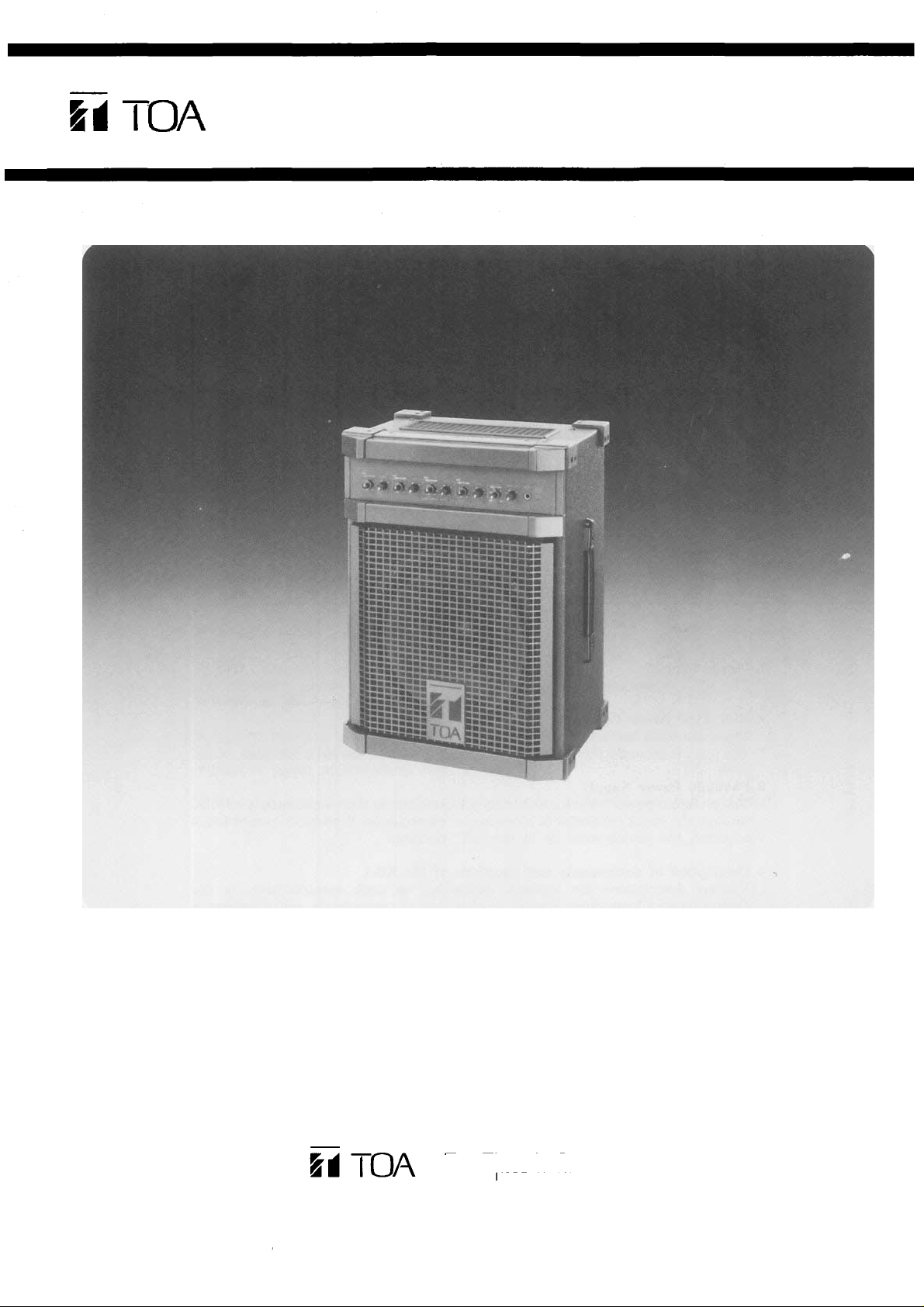
ELECTRONIC MUSIC AMPLIFICATION SYSTEM
Model KD-1
T o a Electric Co., Ltd.
KOBE, JAPAN
Page 2

Contents
Precautions .................................................................................. 1
General Description ....................................................................... 2
Features ...................................................................................... 2
Front Panel: Names of components & their usage ............................... 3
Rear Panel: Names of components & their usage ................................. 4
Block and Level Diagrams .............................................................. 5
Specifications ........................................................................... 5~6
Appearance .................................................................................. 6
Precautions
1. Power Supply
The KD-1 is designed to operate on local AC (50/60Hz) Mains, ±10%.
2. XLR Type Audio Connector
The connectors are wired as follows.
The pin 1 is ground (shield), the pin 2 c o l d (low, minus), t he pin 3 hot (h igh, plus).
3. Phantom Power Supply
The phantom power switch on channel 1 input permits the user t o supply 48 V D C
through the input connector to a condenser microphone. If phantom power is not
required, the switch must be in the "off" position.
4. Description of components and functions of the KD-1
Various descriptions are applied, depending on each manufacturer. In our
Operating and Instruction Manual explanation of components and functions is
made according to Toa's usage fo r them.
1
Page 3
General Description
The TOA KD-1 is a complete electronic music amplification system in a single
portable package, consisting of a mixer, spring reverberation unit, power amplifier,
and full range speaker system.
The mixer section provides four input channels, and an effects patching loop with
crossfade and level controls. Each input features 2-band active EQ, and level control.
Input channels 1 and 2 feature Effects on/off switches, while channels 3 and 4 feature
input sensitivity switches. Channel 1 also features an electronically balanced XLR mic
input connector with switchable 48 volt phantom power, for use with condenser-type
microphones.
The 50 watt RMS internal power amplifier features Auto Comp compression circuitry,
with an LED indicator, to ensure distortion-free performance and protection for the
internal 12-inch heavy duty speaker system.
The KD-1 is covered in a durable and attractive high tech gray vinyl fabric.
Features
System Features
Four input channels
50 watts power amplifier output
Auto Comp compression circuitry w/indicator
Power amplifier protection circuitry w/indicator
Built-in heavy-duty 12"(30cm) two-way loudspeaker
Built-in spring reverberation unit
Effects patching loop, returnable to system mixing buss with crossfade and level
controls
Each Input Channel
Two band EQ
Input channel 1 has electronically balanced XLR mic input connector with
switchable 48 volt phantom power
Input channel 1 and 2 has Effects ON/OFF switches
Input channel 3 and 4 has Input Level Selector switches
2
Page 4

Front Panel
Low Equalizer Control [LOW]
The low EQ control alters the low
frequency response of the input
channel, providing ±15dB at
20Hz of continuously variable active shelving equalization. The
"0" detented position provides
flat audio response.
High Equalizer Control [HI GH]
The high EQ control alters the
high frequency response of the
input channel, providing ±15dB
at 20kHz of continuously variable
active shelving equalization. The
"0" detented position provides
flat audio response.
Cross-fade Control for Reverb
and Effect [REV/EFF X-FD]
When this control is in the center
position, the Reverb signal (thus
the internal reverberation unit)
and EFF RET signals are equally
assigned to the System mixing
buss. Rotating the control
counter-clockwise decreases the
EFF RET signal level, keeping the
original level of the Reverb Signal. Rotating the control clockwise decreases the Reverb signal
level, keeping the original level of
the EFF RET signal.
Reverb/Effect Level Control
[REV/EFF LEVEL]
This control governs the amount
of reverb signal through the reverberation unit (built in), and effect
signal returned throug h the effect
return jack (EFF RET) to the system mixing buss. The singal of
Reverb signal and EFF RET is
controlled simultaneously.
Power/Protect LED Indicator
[POWER/PROTECT]
The LED indicator lights green
when the power switch is "on".
The LED turns red when the
thermal protection circuit is activated, or the internal fuse (for
overload protection) is opened.
Input Channel Level
[LEVEL]
The level control provides continuously variable adjustment of
the channel output to the mixing
busses, thus determining the
level of the channel in the main
sound system mix. The nominal
level of t he input level control is
at the "0" dB position.
System Level Control [SYSTEM
LEVEL]
This control determines the overall volume level of the KD-1 sys-
tem.
Headphone Jack [PHONES]
The headphone jack will accept
any stereo headphone with 8
ohms impedance, or higher. This
jack provides the same signal as
the speaker output. When a plug
is inserted into the jack, the
speaker output is automatically
switched off.
Power Amp Compression
Indicator [COMP]
The Comp LED lights when the
internal compressor is activated.
The compressor is provided to
protect the speaker system by
compressing the input signal
level of the power amplifier when
clipping occurs in the output
stage. Frequent flashing of the
LED is not reason for alarm.
However, a constant or steady
light indicates that the KD-1 is
being overdriven and that the
internal power amplifier is poss-
ibly "under powered" for that
application. The output level of
the KD-1 should be decreased
until the LED only flashes intermittently.
3
Page 5

Rear Panel
Effect Return Jack [EFF RET]
This 1/4" phone jack is used in
conjunction with the Effect Send
jack to connect an outboard
effects device (i.e, delay or re-
verb) to the KD-1. The Effect
Return jack should be connected
to the output of the effect. Nomin-
al input level is -20dB with an
impedance of 10k ohms.
Aux Input Jack [AUX IN]
The unbalanced 1/4" phone jack
have a nominal input level of
-20dB and an impedance of 10k
ohms.
Effect Send Jack [EF F SEND]
This 1/4" phonejack is used in
conjunction with the Effect Re-
turn jack to connect an outboard
effects device (i.e, delay or reverb) to the KD-1. The Effect Send
jack should be connected to the
input of the Effect. Nominal out-
put level is - l0d B wi t h an impedance of 1k ohms.
1/4" Phone Channel Input
[INPUT]
This jack is a standard, unbalanced 1/4" phone jack, with a
nominal level of -30dB and an
impedance of 100k ohms. When a
plug is inserted into the 1/4" input
jack, the corresponding RCA pin
jack is automatically switched
out of the input circuitry.
RCA Channel Input [INPUT]
The RCA pin input jack is unba-
lanced, with a nominal level of
— 30d B and an impedance of 100k
ohms.
Phantom Power On/Off switch
[PHANTOM]
This switch alternately turns
"on" and "off the phantom power (4 8V DC) for the XLR connector
assigned to Channel 1. The
switch should remain in the off
position when a condenser type
mic is not in
use.
Power Switch [POWER]
The power switch is a three-
position type with the middle
position being the "off' position.
The KD-1 should be operated in
the switch position which produces the lowest amount of system
hum.
AC Power Cord
The power cord is of the three-
wire type wit h proper grounding
facilities built-in. (6ft.)
Caution — The ground pin
should not be removed under any
circumstances. If the KD-1 must
be used without proper ground-
ing facilities, a suitable grounding
adapter should be utilized. Op-
eration of the KD-1 with proper
grounding techniques will result
in less system noise and greatly
reduced shock hazard.
AC
Fuse
Warning: To avoid possible
equipment damage and/or per-
sonnel injury, the fuse should
always be replaced with same
type and rating. Using improper
fuses will also void the warranty.
The KD-1 should always be disconnected from AC outlet prior to
changing fuses. If fuse repeatedly
fails, the unit should be referred
to qualified service personnel for
repair.
Recording Outout Jacks
[RECOUT]
The unbalanced RCA pin jacks
have a nominal output level of
-10dB and an impedance of 1k
ohms. The Recording Outputs are
pre-fader signals for connection
to tape recorders. Any change in
the level of the System Level
control will not alter the level of
the recording outputs.
Speaker Jack [EXT. SP]
The external speaker output is a
standard 1/4" phone jack. Speaker
cables (recommend at least #18
gauge wire) should be connected
between the KD-1 and the speaker
systems prior to applying AC
power to the unit. When a plug is
inserted into the external speaker
jack, the internal speaker is automatically switched off.
Caution — The KD-1 should never be operated into less than an 8ohm speaker load.
Input Level Selector [PAD]
The slide switch provides 30dB
attenuation for the 1/4" Input
Jack, and RCA pin Input Jack at
the "30dB" position. The correct
setting should be made according
to the output level of the equipment connected. For example, an
instrument with a "HOT" output
may overload the input circuitry,
resulting in a distorted or "FUZ-
ZY" sound.
Balanced XLR Microphone Input
[MIC]
The XLR-type microphone input
connector (channel 1 only) is
electronically balanced with a
nominal level of -60dB and an
input impedance of 1k ohms.
Phantom powering is provided
for use with condenser-type microphones (see PHANTOM). The
microphone input is automatical-
ly disconnected when either the
corresponding RCA Pin jack or
the 1/4" phone jack is used.
Effects ON/OF F Switch [EFF]
The slide switches provide quick
connects or disconnects of indi-
vidual channel input signals
(post-fader) to the effect buss, and
will thus turn the reverb/effect on
or off on that channel.
4
Page 6

Block and Level Diagrams
Specifications
MIXER SECTION
Frequency Response
+0, -3dB 20Hz to 20kHz (INPUT to REC OUT)
Total Harmonic Distortion
Less t han 0.05% -10dB* 1kHz (REC OUT)
Hum and Noise (REC OUT: Open 20Hz to 20kHz)
All Level Control Minimum —85dB
One INPUT Level Control Maximum —80dB
Equalization
LOW ±15dB 20Hz Shelving
HIGH ±15dB 20kHz Shelving
POWER AMPLIFIER SECTION
Power Output
50 watts minimum sine wave continuous average power output
monaural driving 8-ohm over a power band fr om 20 Hz to 50kHz.
The maximum Total Harmonic Distortion (THD) at any power
level from 250 milliwatts to 50 watts shall be no mor e than 0.5%.
50 watts continuous average sine wave power into 8-ohm will less
tha n 0.05% THD at 1kHz.
Frequency Response
+0dB, -2dB 20Hz to 20kHz
Total Harmonic Distortion
Less than 0.05% at 50 watts into 8-ohm at 1kHz
Hum and Noise
-80dB below rated output (IHF-A weighted)
SPEAKER SECTION
Speaker
12"(30cm) two-way speaker
Sensitivity
96dB (1 watt/1 meter)
Frequency Response
70Hz to 14kHz
GENERAL SPECIFICATIONS
Power Consumption
105 watts maximum
Dimensions (W×H×D)
390mm×523mm×281mm
15
3/8"×20
5/8"×11"
Weight
16kg
(35
1bs)
5
Page 7

Specifications
INPUT SPECIFICATIONS
Actual
Input
CHANNEL INPUT
CH1~CH4
MIC CH1
AUX IN
EFF RET
Load
Impedance
OUTPUT SPECIFICATIONS
Output
REG OUT
EFF SEND
HEAD PHONE
EXT.
SP
Stereo phone jack is wired:
Tip=Left, Ring=Right, Sleave=Common.
The XLR type con nector is electronically balanced.
The XLR type connector is wired as follows
PinNo.1-Ground
Pin No.2-Cold (Low)
Pin No.3-Hot (High)
Actual
Source
Impedance
Specifications are subject to change without notice.
For Use
With
Nominal
For Use
With
Nominal
Nominal
-30dB (24mV)
-60dB (0.78mV)
-20dB (78mV)
-20dB (78mV)
Nominal
-10dB (245mV)
-10dB (245mV)
+4dB (1.23V)
50W/8
Input Level
Output Level
MAX. Before Clip
0dB (0.775V)
-30dB (24mV)
+10dB (2.45V)
+ 10d B (2.45V)
0dB is referenced to 0.775V RMS.
MAX. Before Clip
+20dB (7.75V)
+20dB (7.75V)
+20dB (7.75V)
0dB is referenced to 0.775V RMS
Connector
PHONE JACK
RCA PIN JACK
XLR-3-31 TYPE
PHONE JACK
PHONE JACK
Connector
RCA PIN JACK
PHONE JACK
STEREO PHONE
JACK
PHONE JACK
Appearance
6
Page 8

Printe d in Taiwan
133-02-838-2
 Loading...