

Page 1
OPERATING INSTRUCTIONS
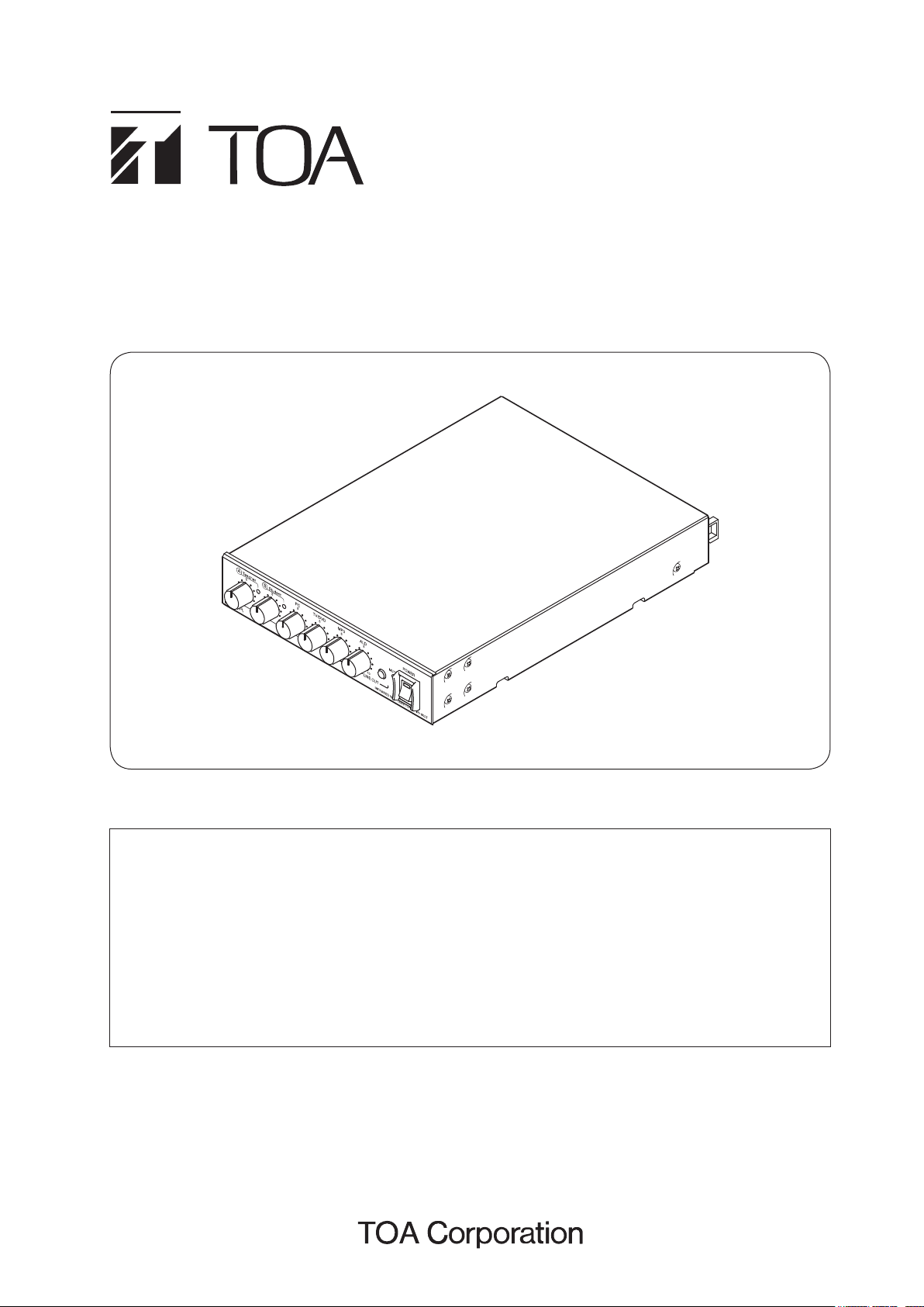
INFRARED WIRELESS TUNER IR-802T
This manual offers not only the installation and usage of the IR-802T but also the general descriptions
for the entire Wireless microphone system* such as system conguration and connection.
For details about the system components, refer to the instruction manual attached to each component.
* The Wireless microphone system is comprised of the following components:
• IR-802T Infrared Wireless Tuner
• IR-820SP Infrared Wireless Speaker
• IR-200M and IR-300M Infrared Wireless Microphones
• IR-200BC Battery Charger
• IR-200BT-2 Ni-MH Battery
Thank you for purchasing TOA’s Infrared Wireless Tuner.
Please carefully follow the instructions in this manual to ensure long, trouble-free use of your equipment.
Page 2

TABLE OF CONTENTS
1. IMPORTANT SAFETY INSTRUCTIONS
........................................... 3
2. SAFETY PRECAUTIONS ............................................................................. 4
3. GENERAL DESCRIPTION .......................................................................... 6
4. FEATURES ............................................................................................................ 6
5. HANDLING PRECAUTIONS ...................................................................... 6
6. NOMENCLATURE AND FUNCTIONS ................................................. 7
Front ............................................................................................................................. 7
Rear ............................................................................................................................. 8
7. SYSTEM CONFIGURATION ....................................................................... 9
8. OPERATIONS ...................................................................................................... 9
8.1. Setting and Adjustment Methods .......................................................................... 9
8.1.1. Infrared wireless microphone setting ........................................................... 9
8.1.2. Sound quality adjustment .......................................................................... 10
8.2. Operation ............................................................................................................ 11
8.2.1. When making microphone announcements ............................................. 11
8.2.2. When broadcasting audio signals from the external equipment .............. 12
8.2.3. When using an Assistive listening device ................................................. 12
9. CONNECTIONS ............................................................................................... 13
10. WHEN MOUNTING IN A RACK .......................................................... 14
11. VOLUME CONTROL COVER ................................................................ 14
12. TROUBLESHOOTING ............................................................................... 15
13. SPECIFICATIONS ........................................................................................ 16
Accessories ............................................................................................................... 16
Optional products ....................................................................................................... 16
2
Page 3

1. IMPORTANT SAFETY INSTRUCTIONS
• Read these instructions.
• Keep these instructions.
• Heed all warnings.
• Follow all instructions.
• Do not use this apparatus near water.
• Clean only with dry cloth.
• Do not block any ventilation openings. Install in accordance with the manufacture's instructions.
• Do not install near any heat sources such as radiators, heat registers, stoves, or other apparatus (including
ampliers) that produce heat.
• Do not defeat the safety purpose of the polarized or grounding-type plug.
A polarized plug has two blades with one wider than the other. A grounding type plug has two blades and a
third grounding prong. The wide blade or the third prong are provided for your safety.
If the provided plug does not t into your outlet, consult an electrician for replacement of the obsolete outlet.
• Protect the power cord from being walked on or pinched particularly at plugs, convenience receptacles, and
the point where they exit from the apparatus.
• Only use attachments/accessories specied by the manufacturer.
• Use only with the cart, stand, tripod, bracket, or table specied by the manufacturer, or
sold with the apparatus.
When a cart is used, use caution when moving the cart/apparatus combination to avoid
injury from tip-over.
• Unplug this apparatus during lightning storms or when unused for long periods of time.
• Refer all servicing to qualied service personnel. Servicing is required when the apparatus has been damaged
in any way, such as power-supply cord or plug is damaged, liquid has been spilled or objects have fallen into
the apparatus, the apparatus has been exposed to rain or moisture, does not operate normally, or has been
dropped.
3
Page 4
2. SAFETY PRECAUTIONS
These precautions apply only to the IR-802T Infrared Wireless Tuner.
For precautions regarding other infrared microphone system devices, please refer to the
instruction manual included with each device.
• Before installation or use, be sure to carefully read all the instructions in this section for correct and safe
operation.
• Be sure to follow all the precautionary instructions in this section, which contain important warnings and/or
cautions regarding safety.
• After reading, keep this manual handy for future reference.
Safety Symbol and Message Conventions
Safety symbols and messages described below are used in this manual to prevent bodily injury and property
damage which could result from mishandling. Before operating your product, read this manual rst and
understand the safety symbols and messages so you are thoroughly aware of the potential safety hazards.
WARNING
CAUTION
Indicates a potentially hazardous situation which, if mishandled, could
result in death or serious personal injury.
Indicates a potentially hazardous situation which, if mishandled, could
result in moderate or minor personal injury, and/or property damage.
WARNING
When Installing the Unit
• Do not expose the unit to rain or an environment
where it may be splashed by water or other liquids,
as doing so may result in re or electric shock.
• Use the unit only with the voltage specied on
the unit. Using a voltage higher than that which is
specied may result in re or electric shock.
• Do not cut, kink, otherwise damage nor modify
the power supply cord. In addition, avoid using the
power cord in close proximity to heaters, and never
place heavy objects -- including the unit itself -- on
the power cord, as doing so may result in re or
electric shock.
When the Unit is in Use
• Should the following irregularity be found during
use, immediately switch off the power, disconnect
the power supply plug from the AC outlet and
contact your nearest TOA dealer. Make no further
attempt to operate the unit in this condition as this
may cause re or electric shock.
· If you detect smoke or a strange smell coming
from the unit.
· If water or any metallic object gets into the unit
· If the unit falls, or the unit case breaks
· If the power supply cord is damaged (exposure of
the core, disconnection, etc.)
· If it is malfunctioning (no tone sounds.)
• To prevent a re or electric shock, never open nor
remove the unit case as there are high voltage
components inside the unit. Refer all servicing to
qualied service personnel.
• Avoid installing or mounting the unit in unstable
locations, such as on a rickety table or a slanted
surface. Doing so may result in the unit falling
down and causing personal injury and/or property
damage.
• Since the unit is designed for indoor use, do not
install it outdoors. If installed outdoors, the aging of
parts causes the unit to fall off, resulting in personal
injury. Also, when it gets wet with rain, there is a
danger of electric shock.
• The apparatus shall be connected to a mains socket
outlet with a protective earthing connection.
• L'appareil doit être branché à une prise d'alimentation
avec mise à la terre de protection.
4
• Do not place cups, bowls, or other containers of
liquid or metallic objects on top of the unit. If they
accidentally spill into the unit, this may cause a re
or electric shock.
• Do not touch the power supply plug during thunder
and lightning, as this may result in electric shock.
Page 5

CAUTION
When Installing the Unit
• To avoid damage to the unit and/or connected
equipment:
· Never connect the IR-820SP connection terminal
to a PC or LAN.
· Never short-circuit the terminal to ground.
• Never plug in nor remove the power supply plug
with wet hands, as doing so may cause electric
shock.
• When unplugging the power supply cord, be sure to
grasp the power supply plug; never pull on the cord
itself. Operating the unit with a damaged power
supply cord may cause a re or electric shock.
• The socket-outlet shall be installed near the
equipment and the plug (disconnecting device)
shall be easily accessible.
• When moving the unit, be sure to remove its power
supply cord from the wall outlet. Moving the unit
with the power cord connected to the outlet may
cause damage to the power cord, resulting in re or
electric shock. When removing the power cord, be
sure to hold its plug to pull.
• Avoid installing the unit in humid or dusty locations,
in locations exposed to the direct sunlight, near the
heaters, or in locations generating sooty smoke
or steam as doing otherwise may result in re or
electric shock.
• Avoid touching the unit’s sharp metal edge to
prevent injury.
• Be sure to follow the instructions below when rackmounting the unit. Failure to do so may cause a re
or personal injury.
· Install the equipment rack on a stable, hard oor.
Fix it with anchor bolts or take other arrangements
to prevent it from falling down.
· When connecting the unit’s power cord to an AC
outlet, use the AC outlet with current capacity
allowable to the unit.
· Rack-mounting screws are not supplied with the
unit. Prepare them that are appropriate for the
equipment rack.
When the Unit is in Use
• Make sure that all volume controls are set to
minimum position before power is switched on.
Loud noise produced at high volume when power is
switched on can impair hearing.
• Use the specied AC adapter for the unit. Note that
the use of other adapter may cause a re.
• If dust accumulates on the power supply plug or
in the wall AC outlet, a re may result. Clean it
periodically. In addition, insert the plug in the wall
outlet securely.
• To avoid electric shocks, be sure to switch off
the unit’s power when connecting the IR-820SP
Infrared Wireless Speaker.
• Switch off the power, and unplug the power supply
plug from the AC outlet for safety purposes when
cleaning or leaving the unit unused for 10 days or
more. Doing otherwise may cause a re or electric
shock.
FCC Compliance
This device complies with Part 15 of the FCC Rules. Operation is subject to the following two conditions:
(1) this device may not cause harmful interference, and
(2) this device must accept any interference received, including interference that may cause undesired
operation.
Any modications made to this device that are not approved by TOA Corporation may void the authority
granted the user by the FCC to operate this equipment.
Note: This equipment has been tested and found to comply with the limits for a Class B digital device, pursuant
to Part 15 of the FCC Rules. These limits are designed to provide reasonable protection against harmful
interference in a residential installation. This equipment generates, uses and can radiate radio frequency
energy and, if not installed and used in accordance with the instructions, may cause harmful interference with
radio communications. However, there is no guarantee that interference will not occur in a particular installation.
If this equipment does cause harmful interference to radio or television reception, which can be determined by
turning the equipment off and on, the user is encouraged to try to correct the interference by one or more of the
following measures:
• Reorient or relocate the receiving antenna.
• Increase the separation between the equipment and the receiver.
• Connect the equipment into an outlet on a circuit different from that to which the receiver is connected.
• Consult the dealer or an experienced radio/television technician for help.
5
Page 6

3. GENERAL DESCRIPTION
The Infrared Wireless Microphone System using this IR-802T is a PA system designed for use in the school
classrooms assuming that their size is about 10 m x 10 m (30 ft x 30 ft).
The IR-802T is a 2-channel Infrared Wireless Tuner employing a xed frequency system with 3 AUX inputs.
It is combined with an infrared wireless microphone and an infrared wireless speaker to make up the infrared
wireless microphone system.
The infrared wireless microphone system eliminates problems with interference or eavesdropping, allowing
simultaneous use in adjacent school classrooms.
4. FEATURES
• Connected to the IR-820SP Infrared wireless speaker (with a built-in infrared receiver) using a single Category
5 straight through cable tted with an RJ-45 connector, the IR-802T receives infrared signals and sends
mixed audio signals through the cable.
• 3 AUX inputs for PC, TV/DVD, and MP3 audio player.
• The IR-802T’s output can be muted by telephone paging input signals.
• Equalizer control knobs for low-, middle-, and high-frequency outputs.
• Mixing output terminal for the ALD (Assistive Listening Device).
• Operated on 24 V DC using the supplied AC adapter (UL/cUL approved product).
• Frequency response optimized to reduce occurrence of acoustic feedback in a classroom whose typical size
is about 10 m x 10 m (30 ft x 30 ft).
5. HANDLING PRECAUTIONS
• The supplied power supply cord is designed for exclusive use with the IR-802T. Never use it with other
equipment.
• Install the IR-802T as far as possible from uorescent lights, digital equipment, PCs and other devices that
generate high-frequency noise.
• The Infrared Wireless Microphone System prevents transmitted contents from being revealed to people
outside walls or other shields. However, since transmissions may be eavesdropped by malicious third parties,
it is strongly suggested that the user take responsibility for carrying out measures to prevent eavesdropping.
TOA assumes no responsibility for any damages that may be sustained without taking appropriate protective
measures against eavesdropping.
• When cleaning, be sure to rst switch off the tuner’s power, then wipe with a dry cloth. If the tuner is extremely
dirty, use a cloth moistened in a neutral detergent. Do not use benzene, thinner, alcohol and chemically-
processed towels, as they can cause damage to the tuner’s components and parts.
6
Page 7

6. NOMENCLATURE AND FUNCTIONS
[Front]
2 3 4 5 6 7 8 9
1. Power switch/indicator
To turn on the power, set this switch to the ON
position, causing the power indicator to light. To
turn off the power, set this switch back to the OFF
position.
2. Teacher’s microphone volume control
Adjusts the sound volume of the Teacher’s infrared
wireless microphone (to be set for Channel A).
Rotate the knob clockwise to increase and
counterclockwise to decrease the volume.
1
6. Auxiliary input volume controls
Adjust the sound volume of each AUX input for PC,
TV/ DVD, and MP3.
Rotate the knob clockwise to increase and
counterclockwise to decrease the volume.
7. ALD (Assistive Listening Device) output volume
control
Adjust the sound volume of the ALD output (8).
Rotate the knob clockwise to increase and
counterclockwise to decrease the volume.
3. Reception indicator (Channel A)
Lights during reception of the infrared wireless
microphone set to Channel A.
4. Student’s microphone volume control
Adjusts the sound volume of the Student’s infrared
wireless microphone(to be set for Channel B).
Rotate the knob clockwise to increase and
counterclockwise to decrease the volume.
5. Reception indicator (Channel B)
Lights during reception of the infrared wireless
microphone set to Channel B.
8. ALD (Assistive Listening Device) output terminal
–10 dB*, 10 kΩ, unbalanced, monaural mini jack.
Connect this terminal to the amplier’s line input
terminal for the assistive listening system.
9. Mute indicator
Lights when the rear-mounted Mute input terminal
(12) receives a telephone paging call from a school
intercom system or other paging equipment, muting
the infrared wireless microphone system.
* 0 dB = 1 V
7
Page 8

[Rear]
10 11 12 13 14 15 16 17
(Bottom Panel)
18
DC24V
10. Cable clip
Run the AC adapter cable through this clip to
prevent its plug from being removed.
AC adapter plug
Cable clip
11. DC inlet terminal
Connect the supplied AC adapter.
12. Mute input terminal
Mutes the infrared microphone system when 25
V line signal from the telephone paging comes in.
13. MP3 input terminal
–10 dB*, 10 kΩ, unbalanced, stereo mini jack.
Accepts MP3 player output signals.
14. TV/DVD input terminal
–10 dB*, 10 kΩ, unbalanced, RCA jacks.
Accepts TV or DVD output signals.
16. Equalizer controls
Adjust low (bass), middle, and high (treble)
frequency response.
Rotate each knob clockwise to increase and
counterclockwise to decrease low, middle, or high
frequency output.
17. IR-820SP connection terminal
Connect this terminal to the IR-820SP Infrared
Wireless Speaker using a Category 5 cable
(straight type).
Notes
• Use a Category 5 plenum cable (straight type)
when routing the cable in locations where
plenum-rated cable is required.
• Cross type cables cannot be used.
CAUTION
To avoid damage to this tuner and/or connected
equipment:
• Never connect this terminal to a PC or LAN.
• Never short-circuit this terminal to ground.
15. PC input terminal
–10 dB*, 10 kΩ, unbalanced, stereo mini jack.
Accepts PC audio output signals.
8
18. Ma rking Plate
Shows the Manufacturer's name, Model name,
and Electrical rating.
* 0 dB = 1 V
Page 9

7. SYSTEM CONFIGURATION
Category 5 cable (straight type)
IR-820SP
Infrared Wireless Speaker
IR-200M
Infrared Wireless Microphone
IR-802T
Infrared Wireless Tuner
IR-200BC
Battery Charger
IR-200BT-2
Ni-MH Battery
for Infrared wireless microphones
(pack of 2)
IR-300M
Infrared Wireless Microphone
MB-15B-BK
Half Width Blank Panel
8. OPERATIONS
8.1. Setting and Adjustment Methods
8.1.1. Infrared wireless microphone setting
Set the channel selector switch of the Teacher's Infrared wireless microphone to Channel A and that of the
Student's Infrared wireless microphone to Channel B.
[IR-200M][IR-300M]
[Inside the battery case]
[Inside of the battery cover]
(Rear)
Note
Channel selector switch
Channel selector switch
(Front)
For details about the setting method, refer to the instruction manual supplied with the infrared wireless
microphone.
9
Page 10

8.1.2. Sound quality adjustment
Adjust the sound quality when installing the IR-802T.
The example here shows the procedure to adjust the sound quality of the IR-802T using the infrared wireless
microphone.
Rear
4
IR-802T
2
3
IR-200M
Infrared Wireless Microphone
1
2
IR-300M
Infrared Wireless Microphone
Step 1. Turn on the unit’s power switch.
The power indicator lights.
Step 2. Turn on the infrared wireless microphone’s power switch.
The reception indicator lights for the channel receiving a signal.
Step 3. Adjust the volume control knob for an appropriate output sound.
Note
Output signal distortion is more likely to increase when the volume control knob is set beyond the “7”
position.
Step 4. Adjust the equalizer controls for an appropriate sound quality.
Each of low-, middle-, and high-frequency outputs can be individually adjusted.
Notes
• Sound quality of the infrared wireless microphones and each audio signal input to the AUX terminals
cannot be individually adjusted.
• Acoustic feedback tends to occur when the MID level is set relatively high.
10
Lights
Page 11

8.2. Operation
8.2.1. When making microphone announcements
IR-802T
2
3
IR-200M
Infrared Wireless Microphone
1
2
IR-300M
Infrared Wireless Microphone
Step 1. Turn on the unit’s power switch.
The power indicator lights.
Step 2. Turn on the infrared wireless microphone’s power switch.
The reception indicator lights for the channel receiving a signal.
Step 3. Adjust the volume control knob for an appropriate output sound.
Notes
• Output signal distortion is more likely to increase when the volume control knob is set beyond the “7”
position.
• When a telephone paging call from a school intercom system or other paging equipment enters the
unit, the Mute indicator lights and the current broadcast being made from the unit is muted.
• Do not cover the microphone head with your hand(s), as doing so may cause acoustic feedback* to
occur.
*
A phenomenon that squealing will occur when sound from the speakers enters the microphone, is
then re-amplied, and output through the speakers, forming a feedback loop.
Lights
11
Page 12

8.2.2. When broadcasting audio signals from the external equipment
3
IR-802T
Step 1. Turn on the unit’s power switch.
The power indicator lights.
Step 2. Turn on the external equipment's power switch, then reproduce audio signals.
Step 3. Adjust the corresponding Auxiliary input volume control for an appropriate output sound.
Notes
• Adjust each input volume control knob depending on the audio signal input level from the external
equipment.
• When a telephone paging call from a school intercom system or other paging equipment enters the
unit, the Mute indicator lights and the current broadcast being made from the unit is muted.
1
8.2.3. When using an Assistive listening device
1 23
IR-802T
Step 1. Connect the Assistive listening system to the ALD output terminal on the front panel.
Step 2. Turn on the unit’s power switch.
The power indicator lights.
Step 3. Adjust the ALD output volume control for an appropriate output sound.
Note
When a telephone paging call from a school intercom system or other paging equipment enters the
unit, the Mute indicator lights and the current broadcast being made from the unit is muted.
12
Page 13

9. CONNECTIONS
CAUTION
• To avoid electrical shocks, be sure to switch off the IR-802T’s power when connecting the IR-820SP.
• To avoid damage to the IR-802T and/or connected equipment:
· Never connect the “TO IR-820SP” terminal to a PC or LAN.
· Never short-circuit this terminal to ground.
Category 5 cable (straight type)
IR-820SP
Infrared Wireless Speaker
Notes
AC adapter plug
Front
Cable clip
Run the AC adapter
cable through this clip to
prevent its plug from
being removed.
• Connect the “TO IR-820SP” terminal to the
IR-820SP Infrared Wireless Speaker using
a Category 5 cable (straight type).
• Use a Category 5 plenum cable (straight
type) when routing the cable in locations
where plenum-rated cable is required.
• Cross type cables cannot be used.
• The cable length must not exceed 50 m
(54.68 yd).
To ALD (Assistive Listening
Device) equipment
AC adapter
(accessory,
UL/cUL
approved
product)
To AC mains
IR-802T
DC24V
PC
TV/DVD
MP3 player
From a school intercom system or
other paging equipment
13
Page 14

10. WHEN MOUNTING IN A RACK
Fiber washer (for M5)5 x 12 rack mounting screw
Use the optional MB-15B-BK Half Width Blank Panel when installing the unit in a 19" rack (1 unit size.)
The MB-15B-BK consists of all the rack-mounting parts such as brackets and screws as shown below.
Be sure to remove the rubber feet located on the unit’s bottom surface before mounting.
3 x 8 tapping screw
3 x 14 tapping screw*
IR-802T
Blank bracket
3 x 14 tapping screw*
Rack mounting bracket
* Secure the brackets with the screws supplied with the MB-15B-BK after removing the case holding screws,
which are no longer used.
11. VOLUME CONTROL COVER
To prevent the accidental change of the setting of the volume controls, remove the knobs after setting them to
the desired position and attach the optional cover instead.
14
Volume control cover
(accessory)
Input volume control knob
Page 15

12. TROUBLESHOOTING
Symptom Cause and Points to Check Remedy
The power indicator does not
light when the power switch is
turned on.
The power indicator ashes. The connection cable to IR-820SP
Power plug is unplugged from an
AC mains outlet.
is possibly failed.
Plug the power plug into an AC wall
outlet.
Conrm correctness of the connection
to IR-820SP and connection cable.
If faulty is found, connect correctly
or replace the cable with appropriate
one.
No signal received. Infrared wireless microphone’s
power switch is not set to ON.
Infrared wireless microphone’s
battery has become discharged.
The microphones’ channels are
incorrectly set as follows:
Teacher’s microphone: Channel B
Student’s microphone: Channel A
No sound outputs. IR-802T is not connected to IR-
820SP properly.
External equipment is not connected
to IR-802T properly.
Sound is too faint to hear. IR-802T’s volume control is set to
too low a level.
The volume control of the external
equipment is set to too low a level.
Noise or strange (i.e. muddy)
sound is heard.
Short transmission distance. IR-820SP is not properly installed. Install IR-820SP properly.
IR-820SP is installed in close
proximity to a device generating
radio noise or infrared light.
Teacher’s microphone and student’s
microphone are set at the same
channel.
Set the microphone’s power switch to
ON.
Replace the battery with a new one.
If a rechargeable battery is used,
recharge it.
Set the microphones’ channels as
follows:
Teacher’s microphone: Channel A
Student’s microphone: Channel B
Conrm correctness of the connection
to IR-820SP and connection cable. If
faulty is found, connect correctly or
replace the cable with appropriate
one.
Connect correctly.
Set the IR-802T’s volume control to
an appropriate volume level.
Set the volume control of the external
equipment to an appropriate volume
level.
Install IR-820SP properly, referring
to “Installation precautions” for the
infrared wireless speaker.
Set the microphones’ channels as
follows:
Teacher’s microphone: Channel A
Student’s microphone: Channel B
Microphone’s volume controls
are not adjustable.
Acoustic feedback occurs. The microphone head is covered
The microphones’ channels are
incorrectly set as follows:
Teacher’s microphone: Channel B
Student’s microphone: Channel A
with your hand(s).
The MID level of the equalizer
controls is set relatively high.
Set the microphones’ channels as
follows:
Teacher’s microphone: Channel A
Student’s microphone: Channel B
Do not cover the microphone head
with your hand(s).
Decrease the MID level of the
equalizer controls.
15
Page 16

13. SPECIFICATIONS
Version CE-GB CU
Power Source 230 V AC, 50/60 Hz
(supplied AC adapter must be used)
(supplied AC adapter must be used)
Power Consumption 8 W (based on UL standards)
Max. 40.8 W (rated output at IR-820SP)
Receiving Frequency Teacher (Channel A): 3.100 MHz
Student (Channel B ): 3.350 MHz
Receiver Sensitivity 50 dB or more, Signal to Noise ratio (40 dBµV input, 1 kHz modulation,
±4.8 kHz deviation)
Signal to Noise Ratio Tuner: 60 dB or more (60 dBµV input, 1 kHz modulation, ±4.8 kHz deviation,
A-weighted, Equalization: Centered)
AUX: 75 dB or more (A-weighted, Equalization: Centered)
Tone Squelch
32.768 kHz
Frequency
Input AUX PC:
AUX DVD/TV:
AUX MP3:
Mute:
line, –10 dB*, 10 kΩ, unbalanced, stereo mini jack (internal mixing)
line, –10 dB*, 10 kΩ, unbalanced, 2P RCA jack (internal mixing)
line, –10 dB*, 10 kΩ, unbalanced, stereo mini jack (internal mixing)
25 V line signals of telephone paging from a school intercom
system
Output ALD (Assistive Listening Device):
line, –10 dB*, 10 kΩ, unbalanced, monaural
mini jack
Speaker:
RJ45 (dedicated terminal for IR-820SP
connection)
Equalization High: ±10 dB at 10 kHz
Mid: ±10 dB at 1.3 kHz
Low: ±10 dB at 100 Hz
Mute Function Muted by 25 V line signals
LED Indicator Power (green) x 1, Infrared reception (yellow) x 2, Mute (red) x 1
Operating Temperature –10 to +50 °C (14 to 122 °F)
Operating Humidity 90 %RH or less (no condensation)
Finish Panel: Aluminium, black
Case:
Steel plate, black
Dimensions 210 (w) x 46 (h) x 312 (d) mm (8.27" x 1.81" x 12.28")
Weight 1.8 kg (3.97 lb)
120 V AC, 50/60 Hz
* 0 dB = 1 V
Note: The design and specifications are subject to change without notice for improvement.
• Accessories
AC adapter (UL/cUL approved product, DC cord length: 1.8 m or 5.91 ft) ............. 1
AC power cord (2 m or 6.56 ft) ............................................................................... 1
Volume control cover .............................................................................................. 6
Removable terminal plug (2 pins) ........................................................................... 1
• Optional product
MB-15B-BK Half Width Blank Panel
Traceability Information for Europe (EMC directive 2004/108/EC)
Manufacturer:
TOA Corporation
7-2-1, Minatojima-Nakamachi, Chuo-ku, Kobe, Hyogo, Japan
Authorized representative:
TOA Electronics Europe GmbH
Suederstrasse 282, 20537 Hamburg,Germany
URL: http://www.toa.jp/
133-07-00014-00
 Loading...