

Page 1
OPERATING INSTRUCTIONS
INFRARED WIRELESS TUNER IR-702T
CH
A
VOLUME
IR
CH
B
VOLUME
POWER
IR
OFF
ON
Thank you for purchasing TOA's Infrared Wireless Tuner.
Please carefully follow the instructions in this manual to ensure long, trouble-free use of your equipment.
This manual describes the installation and usage of the entire system* using the IR-702T Infrared
Wireless Tuner as well as the IR-702T.
* The system described in this manual is comprised of the following components:
• IR-702T Infrared Wireless Tuner
• IR-200M and IR-300M Infrared Wireless Microphones
• IR-500R, IR-510R, and IR-520R Infrared Wireless Receivers
• IR-200BC Battery Charger
• IR-200BT-2 Ni-MH Battery
• YW-1022 and YW-1024 Distributors
Note
For the installation and usage of the IR-702T when used in combination with the IR-700D
Infrared Wireless Distributor, refer to the installation manual enclosed with the IR-700D.
133-07-275-8B
Page 2

2
TABLE OF CONTENTS
1. SAFETY PRECAUTIONS ...................................................................................................... 3
2. GENERAL DESCRIPTION .................................................................................................... 4
3. FEATURES ................................................................................................................................. 4
4. HANDLING PRECAUTIONS ................................................................................................ 4
5. NOMENCLATURE AND FUNCTIONS
Front ............................................................................................................................................... 5
Rear ................................................................................................................................................ 5
6. OPERATIONS ........................................................................................................................... 6
7. SYSTEM CONFIGURATION EXAMPLES
7.1.Using 2 Infrared Wireless Receivers ........................................................................................7
7.2. Using 4 Infrared Wireless Receivers .......................................................................................7
7.3.
Simultaneous Use of the Infrared Wireless Microphone System and the Infrared Conference System
..... 8
8. CONNECTION EXAMPLE .................................................................................................... 9
9. INFRARED WIRELESS RECEIVER COVERAGE AREA
9.1. IR-500R and IR-520R (Wall-mounted and microphone stand-mounted type) ....................... 10
9.2. IR-510R (Ceiling-mounted type) ............................................................................................10
10. INSTALLING THE INFRARED WIRELESS RECEIVER
10.1. Installation Precautions ....................................................................................................... 11
10.2. Infrared Wireless Receiver Installation Examples ............................................................... 12
10.3. When Simultaneously Using Both the Infrared Wireless Microphone
System and the Infrared Conference System ...................................................................... 13
11. INSTALLING THE IR-500R INFRARED WIRELESS RECEIVER
11.1. Wall Mounting ...................................................................................................................... 14
11.2. Adjusting the Reception Angle ............................................................................................ 16
12. INSTALLING THE IR-510R INFRARED WIRELESS RECEIVER
12.1. Ceiling Mounting .................................................................................................................. 19
13. INSTALLING THE IR-520R INFRARED WIRELESS RECEIVER
13.1. Wall Mounting ...................................................................................................................... 20
13.2. Mounting on a Microphone Stand ........................................................................................ 21
14. INSTALLING THE INFRARED WIRELESS TUNER
14.1. Mounting in a Rack .............................................................................................................. 22
14.2. Mounting on a Desk ............................................................................................................. 22
15. INFRARED WIRELESS RECEIVER TO TUNER WIRING
15.1. Wiring Precautions .............................................................................................................. 23
15.2. When Using the Distributor YW-1022/1024 ......................................................................... 23
15.3. When Using the Infrared Wireless Distributor IR-700D ....................................................... 23
15.4. Wiring Examples .................................................................................................................. 24
16. SUPPLEMENTARY REMARKS
16.1. Wiring Design Confirmation ................................................................................................. 25
16.2. Design Examples ................................................................................................................. 25
17. TROUBLESHOOTING .......................................................................................................... 27
18. SPECIFICATIONS .................................................................................................................. 28
Page 3
3
When Installing the Unit
• Do not expose the unit to rain or an environment
where it may be splashed by water or other liquids,
as doing so may result in fire or electric shock.
• Use the unit only with the voltage specified on the
unit. Using a voltage higher than that which is
specified may result in fire or electric shock.
• Do not cut, kink, otherwise damage nor modify the
power supply cord. In addition, avoid using the
power cord in close proximity to heaters, and never
place heavy objects -- including the unit itself -- on
the power cord, as doing so may result in fire or
electric shock.
When the Unit is in Use
• Should the following irregularity be found during
use, immediately switch off the power, disconnect
the power supply plug from the AC outlet and
contact your nearest TOA dealer. Make no further
attempt to operate the unit in this condition as this
may cause fire or electric shock.
· If you detect smoke or a strange smell coming
from the unit.
· If water or any metallic object gets into the unit
· If the unit falls, or the unit case breaks
· If the power supply cord is damaged (exposure of
the core, disconnection, etc.)
· If it is malfunctioning (no tone sounds.)
• To prevent a fire or electric shock, never open nor
remove the unit case as there are high voltage
components inside the unit. Refer all servicing to
qualified service personnel.
• Do not place cups, bowls, or other containers of
liquid or metallic objects on top of the unit. If they
accidentally spill into the unit, this may cause a fire
or electric shock.
• Do not touch a power supply plug during thunder
and lightning, as this may result in electric shock.
When Installing the Unit
• Never plug in nor remove the power supply plug
with wet hands, as doing so may cause electric
shock.
• When unplugging the power supply cord, be sure
to grasp the power supply plug; never pull on the
cord itself. Operating the unit with a damaged
power supply cord may cause a fire or electric
shock.
• When moving the unit, be sure to remove its power
supply cord from the wall outlet. Moving the unit
with the power cord connected to the outlet may
cause damage to the power cord, resulting in fire or
electric shock. When removing the power cord, be
sure to hold its plug to pull.
• Avoid installing the unit in humid or dusty locations,
in locations exposed to the direct sunlight, near the
heaters, or in locations generating sooty smoke or
steam as doing otherwise may result in fire or
electric shock.
• Refer all installation work to the dealer from where
the unit was purchased. Installation requires
extensive technical knowledge and experience.
Improper installation may result in personal injury
or electric shock.
1. SAFETY PRECAUTIONS
These precautions apply only to the IR-702T Infrared Wireless Tuner.
For precautions regarding other infrared microphone system devices, please refer to the
instruction manual included with each device.
• Before installation or use, be sure to carefully read all the instructions in this section for correct and safe
operation.
• Be sure to follow all the precautionary instructions in this section, which contain important warnings and/or
cautions regarding safety.
• After reading, keep this manual handy for future reference.
WARNING
Indicates a potentially hazardous situation which, if mishandled, could
result in death or serious personal injury.
Indicates a potentially hazardous situation which, if mishandled, could
result in moderate or minor personal injury, and/or property damage.
WARNING
CAUTION
CAUTION
Page 4

4
When the Unit is in Use
• Use the AC adapter supplied with the unit. Note
that the use of other adapter may cause a fire.
• If dust accumulates on the power supply plug or in
the wall AC outlet, a fire may result. Clean it
periodically. In addition, insert the plug in the wall
outlet securely.
• Switch off the power, and unplug the power supply
plug from the AC outlet for safety purposes when
cleaning or leaving the unit unused for 10 days or
more. Doing otherwise may cause a fire or electric
shock.
2. GENERAL DESCRIPTION
The IR-702T is a 2-channel infrared wireless tuner employing a fixed frequency system.
This tuner is combined with an infrared wireless microphone and an infrared wireless receiver to make up the
infrared wireless microphone system.
The infrared microphone system eliminates problems with interference or eavesdropping, allowing
simultaneous use in adjacent conference rooms or school classrooms.
3. FEATURES
• The YW-1022 or YW-1024 Distributor allows up to 4 infrared wireless receivers to be installed.
• Up to 16 infrared wireless receivers can be installed with the use of the IR-700D Infrared Wireless
Distributor.
• Since the IR-702T tuner uses a frequency band that does not interfere with that of the infrared conference
system (TS-800 and TS-900 Series), both the infrared wireless microphone system and the conference
system can be simultaneously installed in the same location.
4. HANDLING PRECAUTIONS
• The supplied power supply cord is designed for exclusive use with the IR-702T. Never use it with other
equipment.
• Install the IR-702T as far as possible from fluorescent lights, digital equipment, PCs and other devices that
generate high-frequency noise.
• The IR-702T is an infrared wireless system which prevents transmitted contents from being revealed to
people outside walls or other shields. However, since transmissions may be eavesdropped by malicious
third parties, it is strongly suggested that the user take responsibility for carrying out measures to prevent
eavesdropping. TOA assumes no responsibility for any damages that may be sustained without taking
appropriate protective measures against eavesdropping.
• When cleaning, be sure to first switch off the tuner's power, then wipe with a dry cloth. If the tuner is
extremely dirty, use a cloth moistened in a neutral detergent. Do not use benzene, thinner, alcohol and
chemically-processed towels, as they can cause damage to the tuner's components and parts.
This device complies with Part 15 of the FCC Rules. Operation is subject to the following two conditions:
(1) this device may not cause harmful interference, and
(2) this device must accept any interference received, including interference that may cause undesired
operation.
Any modifications made to this device that are not approved by TOA Corporation may void the authority
granted the user by the FCC to operate this equipment.
FCC Compliance
Page 5
5
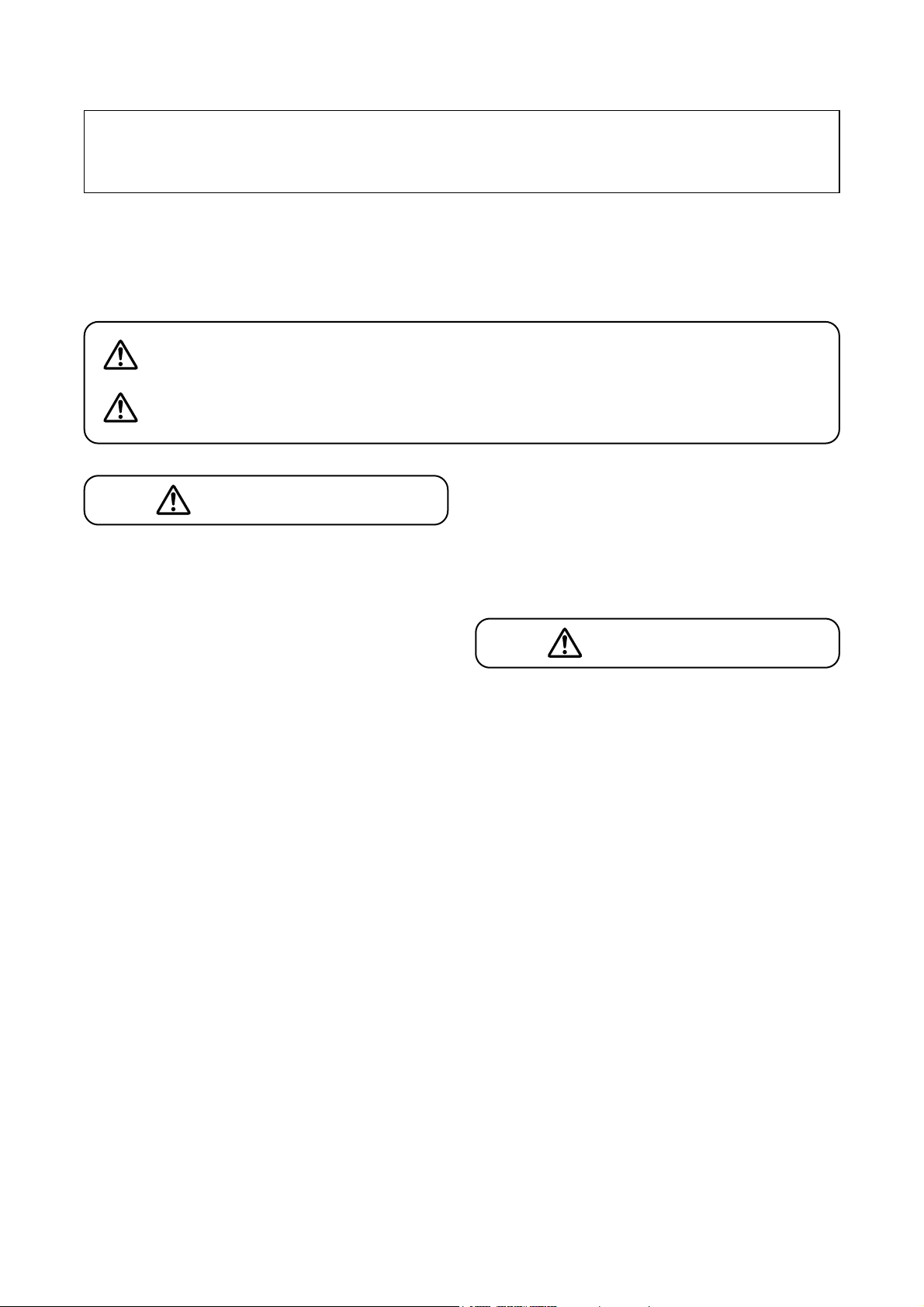
1. Power switch
Press this switch to turn on the power. To turn off
the power, press this switch again.
2. Power indicator
Lights when the power is switched on.
3. Reception indicator [IR]
Lights during reception.
4. Color label attachment area
Attach a color label (accessory) of the same color
as that of the infrared wireless microphone to be
used in combination with the tuner.
5. Volume control knob
Adjusts the sound volume of the infrared wireless
microphone.
6. Cable Clip
Run the AC adapter cable through this clip to
prevent its plug from being removed.
7. DC inlet [DC IN]
Connect the supplied AC adapter.
8. Receiver input terminals [IR IN]
Connect the infrared wireless receiver or the
distributor. Up to 4 infrared wireless receivers
can be connected with the use of the YW-1022
(2-Branch Distributor) or the YW-1024 (4-Branch
Distributor).
Note that only one YW-1022 or YW-1024
Distributor can be connected per input channel.
Up to 16 infrared wireless receivers can be
connected with the use of the IR-700D Infrared
Wireless Distributor. For cable connections when
using the IR-700D, refer to the installation
manual enclosed with the IR-700D.
9. CH B output terminal [CH B]
Connect this terminal to the amplifier line input
terminal for public address applications.
This terminal outputs only the CH-B audio signal.
10. CH A/MIX output terminal [CH A/MIX]
Connect this terminal to the amplifier line input
terminal for public address applications.
This terminal outputs either the CH-A audio
signal alone or a mixed CH-A and CH-B audio
signal depending on the setting of the CH A/MIX
output selector switch (11).
11. CH A/MIX output selector switch
• CH A
Only the CH-A signal is delivered at the CH
A/MIX output terminal (10).
• MIX (default position)
Mixed CH-A and CH-B signals are delivered at
the CH A/MIX output terminal (10).
5. NOMENCLATURE AND FUNCTIONS
1 23 4 5
[Front]
CH A
VOLUME
IR
Note: Functions of the (3), (4), and (5) for the Channel A also apply to the Channel B (CH-B).
6 7 8 9
[Rear]
DC IN
24V 0.6A(max)
IR IN OUTPUT
75 Ω
12
CH B
VOLUME
IR
ON
OFF
POWER
10 11
–10dBV/600Ω
CH B
CH A/MIX
CH A
MIX
AC adapter plug
Cable clip
Page 6
6
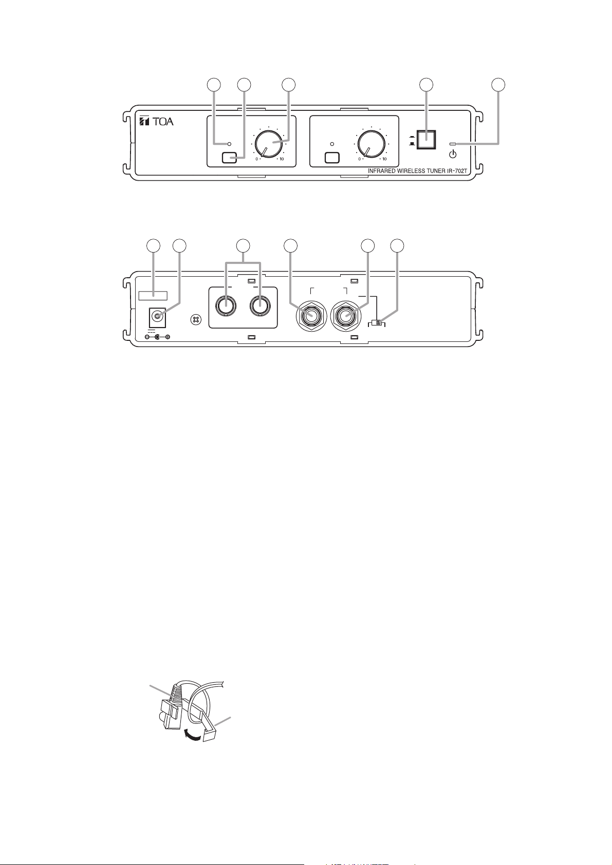
6. OPERATIONS
Note: The example here shows the operation of the Channel A. This operation also applies to the Channel B.
Step 1. Turn on the unit's power switch.
Step 2. Turn on the infrared wireless microphone's power switch.
The reception indicator lights for the channel receiving a signal.
Note
If the reception indicator does not light, the infrared wireless microphone is not set to the same
channel as that of the infrared wireless tuner. For channel settings, please refer to the instruction
manual enclosed with the infrared wireless microphone.
Step 3. Adjust the volume control knob for an appropriate output sound.
Note
Output signal distortion is more likely to increase as the volume control knob is rotated beyond the
"2-o'clock" position.
2
Power switch
3
Volume control knob
VOLUME
CH A
IR
Reception indicator
CH B
IR
VOLUME
1
Power switch
OFF
ON
POWER
Infrared wireless microphone
IR-300M
Infrared wireless microphone
IR-200M
Page 7
7
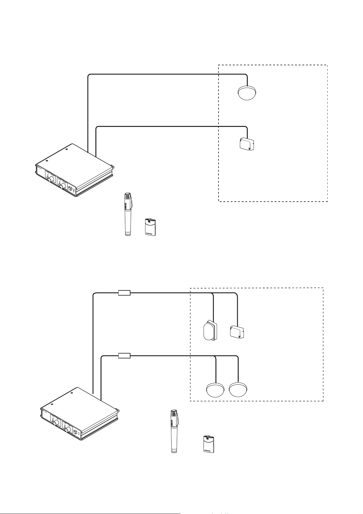
7. SYSTEM CONFIGURATION EXAMPLES
7.1. Using 2 Infrared Wireless Receivers
7.2. Using 4 Infrared Wireless Receivers
Infrared Wireless Tuner
IR-702T
Infrared Wireless Microphone
IR-200M
Infrared Wireless Receiver
IR-500R, IR-510R, or IR-520R
Note
Connect one each of the IR-510R or
IR-520R Infrared Wireless Receivers to
the IR-702T's Receiver input terminals
1 and 2.
Infrared Wireless Microphone
IR-300M
Distributor
YW-1022 (2-branch distributor)
YW-1022
Infrared Wireless Receiver
IR-500R, IR-510R, or IR-520R
Note
Up to 4 infrared wireless
receivers can be connected.
Infrared Wireless Tuner
IR-702T
Infrared Wireless Microphone
IR-200M
Infrared Wireless Microphone
IR-300M
Page 8
8
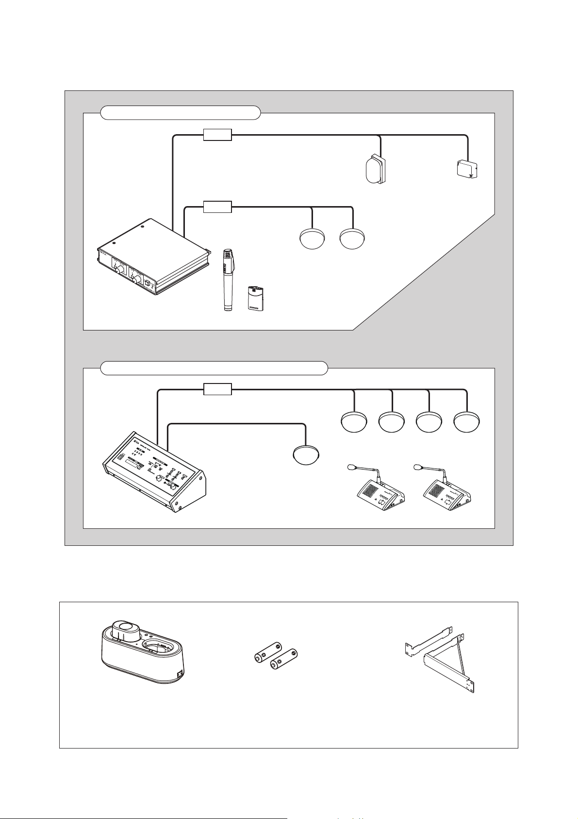
7.3. Simultaneous Use of the Infrared Wireless Microphone System and the Infrared
Conference System
[Infrared Wireless Microphone System-related Equipment]
Infrared Wireless Microphone System
* When connecting
3 or more Infrared
Wireless
Receivers, use
the YW-1024
(4-branch
distributor).
Infrared Wireless Tuner
IR-702T
Infrared Conference System (TS-800 or TS-900 series)
Distributor
YW-1022 (2-branch distributor) *
YW-1022*
Infrared Wireless Microphone
IR-200M
Infrared Wireless Microphone
IR-300M
Infrared Wireless Receiver
IR-500R, IR-510R or
IR-520R
Note
Both systems can be installed
in the same location.
IR-200BT-2
IR-200BC
Battery Charger
Ni-MH Battery
for Infrared wireless microphones
(pack of 2)
MB-WT3
Rack Mounting Bracket
Page 9
9
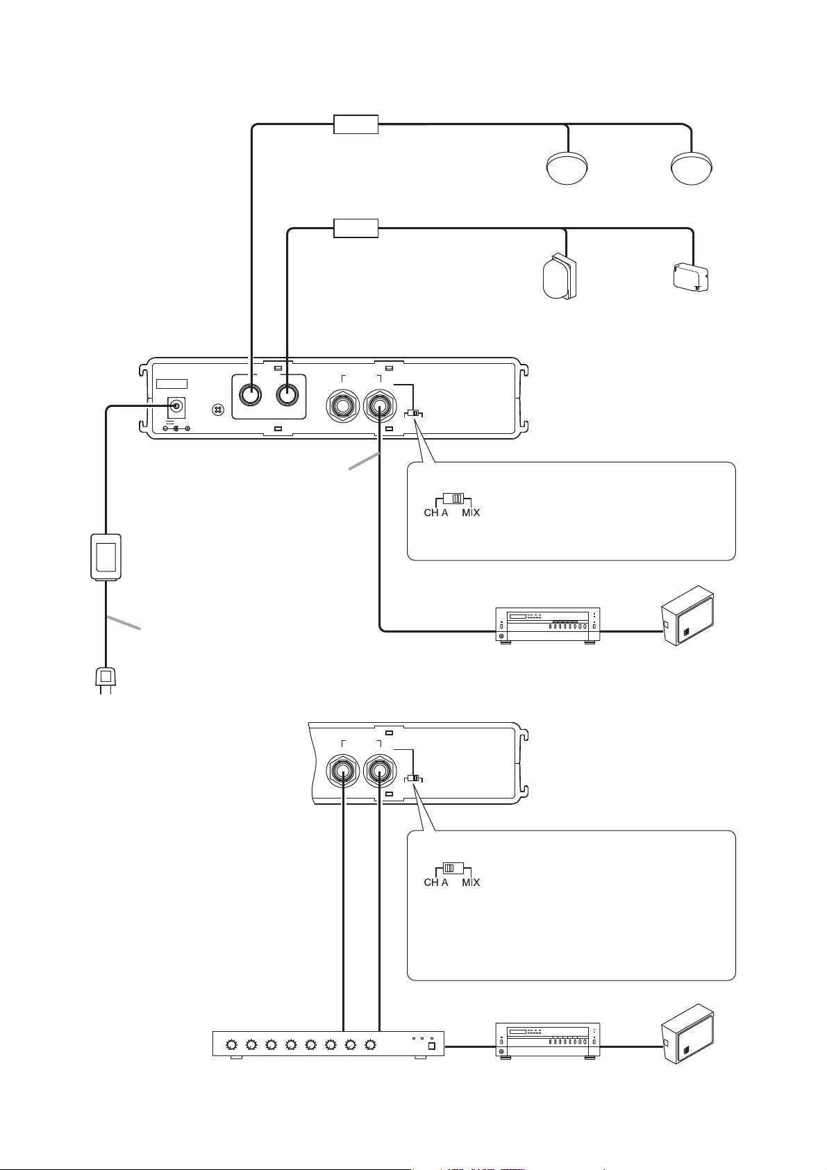
8. CONNECTION EXAMPLE
Distributor
YW-1022 (2-branch distributor)
Infrared Wireless Receiver
IR-500R, IR-510R, or IR-520R
YW-1022
Infrared Wireless Tuner IR-702T
IR IN OUTPUT
75 Ω
DC IN
24V 0.6A(max)
12
Cable with a phone plug
(supplied with the IR-702T)
AC adapter
(supplied with the IR-702T)
Power supply cord
(supplied with the IR-702T)
CH B
CH B
–10dBV/600Ω
OUTPUT
–10dBV/600Ω
CH A/MIX
CH A/MIX
CH A
MIX
Setting the selector switch to the
MIX position outputs mixed CH-A
and CH-B audio signal.
Connect the CH A/MIX terminal to
the amplifier line input, etc.
SpeakerAmplifier
Mixer
CH A MIX
Setting the selector switch to CH-A
independently outputs the audio
signal of CH-A and CH-B.
Connect each of the CH A/MIX and
CH B terminals to the line input of a
mixer or similar device to allow the
signal level to be adjusted by
external equipment.
SpeakerAmplifier
Page 10
10
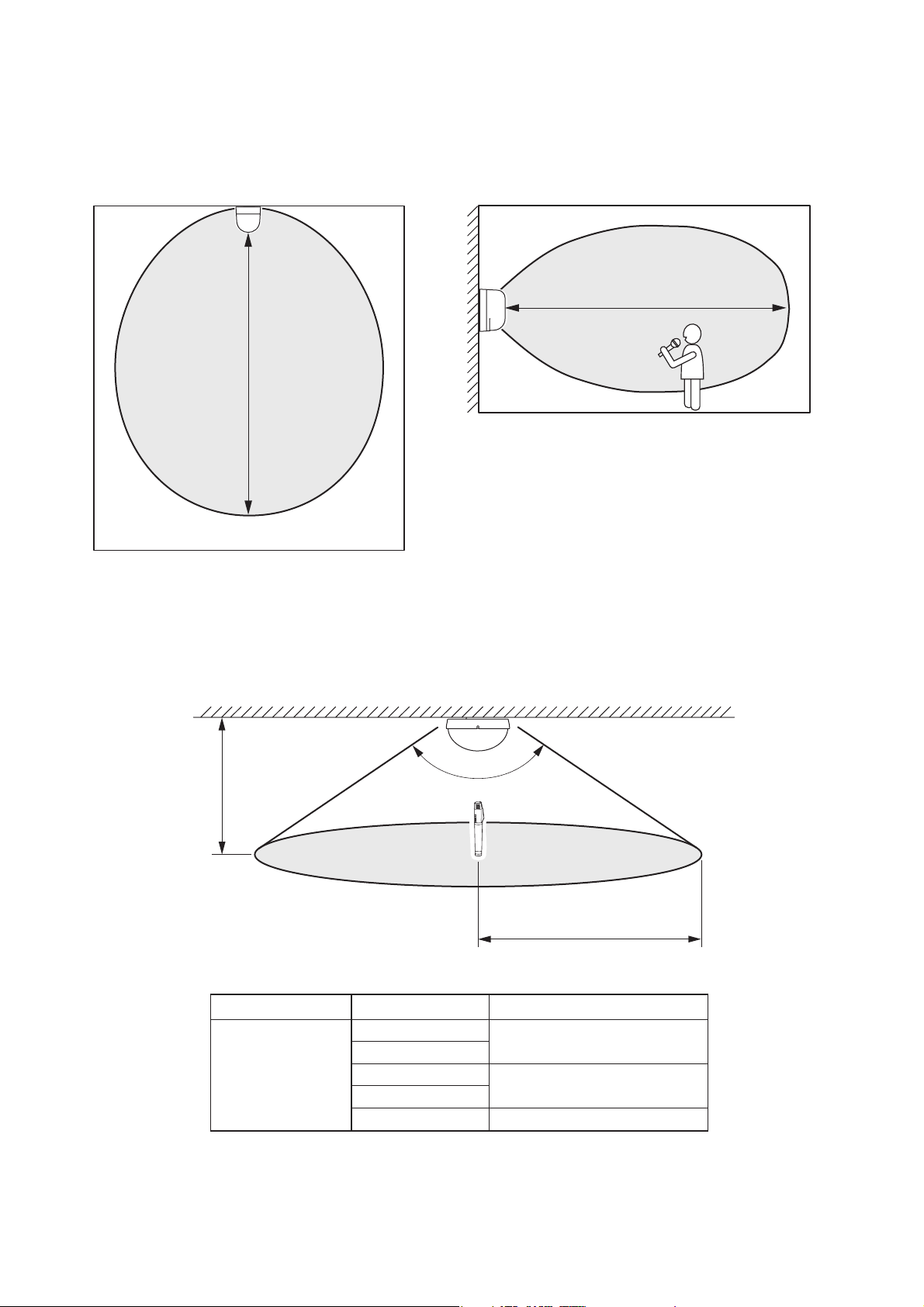
9.2. IR-510R (Ceiling-mounted type)
9. INFRARED WIRELESS RECEIVER COVERAGE AREA
9.1. IR-500R and IR-520R (Wall-mounted and microphone stand-mounted type)
[Horizontal direction] [Vertical direction]
15 m (49.21 ft)
15 m (49.21 ft)
Note
The shaded portion represents the communications area.
Ceiling height
2.5 to 4.5 m
(8.2 to 14.76 ft)
Note
The shaded portion represents
the communications area.
Applicable model
IR-510R
Ceiling height Communications area radius
2.5 m (8.20 ft)
3.0 m (9.84 ft)
3.5 m (11.48 ft)
4.0 m (13.12 ft)
4.5 m (14.76 ft)
150º
Communications area radius
About 7 m (23 ft)
About 6.5 m (21.5 ft)
About 6 m (20 ft)
Page 11
11
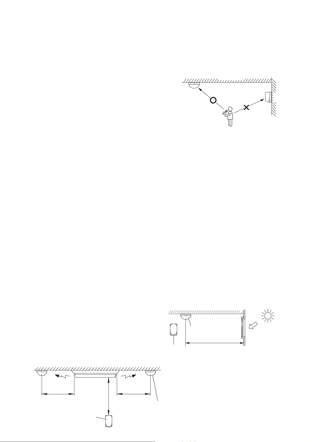
10.1. Installation Precautions
Because the infrared wireless microphone and receiver have their own directivity for infrared transmission and
reception, take care that they are installed and operated under stable communication conditions.
• Number of infrared wireless receivers
Use 2 or more receives.
• Installation Position
· The infrared beam can be blocked by a human body or
other objects. To avoid this, install multiple infrared
wireless receivers that can be viewed from the infrared
wireless microphone.
· Install multiple infrared wireless receivers so as to allow
constant communications between the infrared
microphone and at least one infrared wireless receiver in
any specific situation. When installing the infrared wireless
receivers, take care that they can sufficiently cover the
communications area from different angles. If the infrared
wireless microphone is used in the communications area
where only one infrared wireless receiver is installed,
communications may be interrupted when the infrared
beam is blocked by a human body or other objects.
· Install the infrared receiver at a height of 2 – 3 m (6.56 – 9.84 ft) from the floor.
· Install the infrared wireless receivers at a height that protects them from damage that could result from
being hit by an object.
• Distance between the infrared wireless microphone and receiver
Malfunctions or noise could result from the infrared wireless microphone and receiver being too close to
each other. Keep the infrared wireless microphone at least 2 m (6.56 ft) away from the receiver.
• Radio Noise
Do not install the infrared wireless receiver and cables close to devices that can generate radio noise, such as:
Inverter-powered equipment (fluorescent lights, air-conditioners, etc.), dimmers, digital equipment, PCs and
other computer equipment.
• Infrared Receiver Input Terminal
Take care not to short-circuit the infrared wireless receiver's input terminal and the infrared wireless tuner's
receiver input terminal, as the power supply could be shorted, potentially resulting in equipment failures.
• Sunlight and Fluorescent Lighting
System malfunctions or noise could result from installing the infrared wireless receiver in locations exposed
to sunlight, fluorescent lighting or other infrared generating sources. When installing the receiver, make the
following arrangements so that it is not exposed to infrared sources:
[Avoid Sunlight]
· To prevent equipment from being directly exposed
to sunlight, block the sunlight using curtains or
window shades.
· When mounting the receiver to a ceiling, keep it at
least 2 m (6.56 ft) away from the window.
[Install Away From Fluorescent Lighting]
When installing the receiver, keep it at least 50 cm (1.64 ft) away from the fluorescent lighting.
10. INSTALLING THE INFRARED WIRELESS RECEIVER
[Avoid installing close to other infrared
sources shown below]
· Lighting device
· Liquid crystal projectors, overhead projectors
and incandescent lights
· Plasma displays
· Remote control units, infrared LAN and other
infrared devices
IR-510R
Note
In this figure, the IR-510R receives a signal
from the infrared wireless microphone because
there is no shield between the two.
However, communication to the IR-500R could
be interrupted if the user's body blocks the
beam like a shield.
Ceiling
IR-500R
Wall
Ceiling-mounted type
Sunlight
Wall-mounted type
Over 2 m (6.56 ft)
Over 50 cm
(1.64 ft)
Wall-mounted type
Fluorescent
lighting
Over 50 cm
(1.64 ft)
(1.64 ft)
Ceiling-mounted type
Over 50 cm
Page 12
12
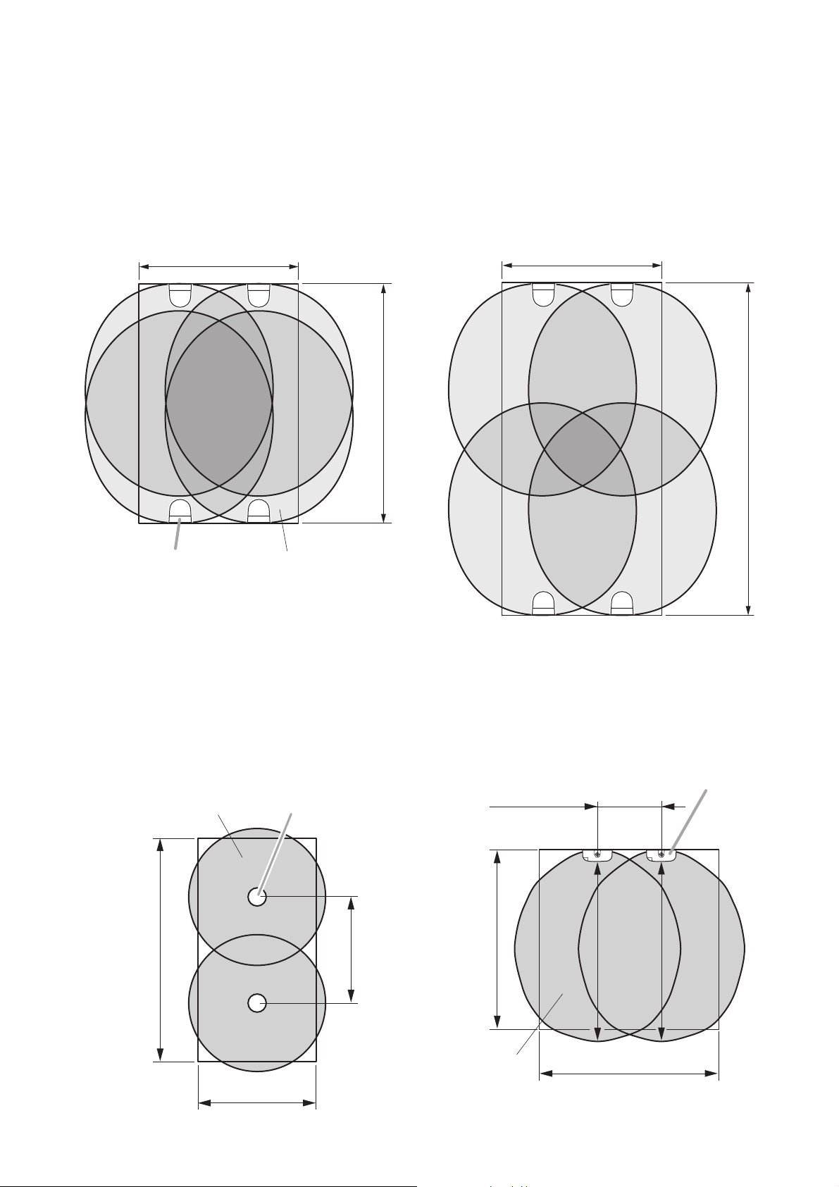
10.2. Infrared Wireless Receiver Installation Examples
The receiver's communications area differs depending on such environmental conditions as the ceiling height.
(Refer to p. 10 "Infrared Wireless Receiver Coverage Area.")
10.2.2. Installing 2 IR-510Rs
Note
Install these 6 m (19.69 ft) to 8 m (26.25 ft) apart
so that each receiver's communications area
overlaps with each other.
10.2.3. Installing 2 IR-520Rs
Note
Install these 6 m (19.69 ft) to 8 m (26.25 ft) apart
so that each receiver's communications area
overlaps with each other.
10.2.1. Installing 4 IR-500Rs and IR-520Rs
Note
In a rectangular room where the usage area is wider than the infrared receiver's communication distance,
install the receivers on the opposite side as well.
12 m (39.37 ft) 12 m (39.37 ft)
18 m (59.06 ft)
IR-500R Infrared wireless receiver's
communications area
Infrared wireless receiver's
communications area
IR-510R
25 m (82.02 ft)
IR-520R
6 – 8 m
(19.69 – 26.25 ft)
18 m (59.06 ft)
10 m (32.81 ft)
6 – 8 m
(19.69 – 26.25 ft)
Infrared wireless receiver's
communications area
12 m (39.37 ft)
15 m (49.21 ft)
12 m (39.37 ft)
15 m (49.21 ft)
Page 13
13
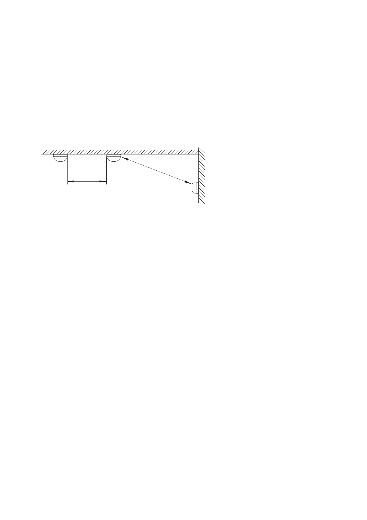
10.3. When Simultaneously Using Both the Infrared Wireless Microphone System and
the Infrared Conference System
The appropriate distance between the infrared wireless receiver (IR-500R, IR-510R, and IR-520R) of the
infrared wireless microphone system and the transmitter/receiver unit (TS-905 and TS-907) of the infrared
conference system differs depending on the size and layout of the room. When simultaneously installing the
two systems in the same location, use the following guidelines on distance:
[Distance between the IR-500R/520R and the TS-905/TS-907]
Keep both units at least 3 m (9.84 ft) away from each other.
[Distance between the IR-510R and the TS-905/TS-907]
Keep both units at least 1.5 m (4.92 ft) away from each other.
Ceiling
Over 3 m (9.84 ft)
IR-510R
Over 1.5 m
(4.92 ft)
TS-905/907
Wall
IR-500R/520R
Page 14
14
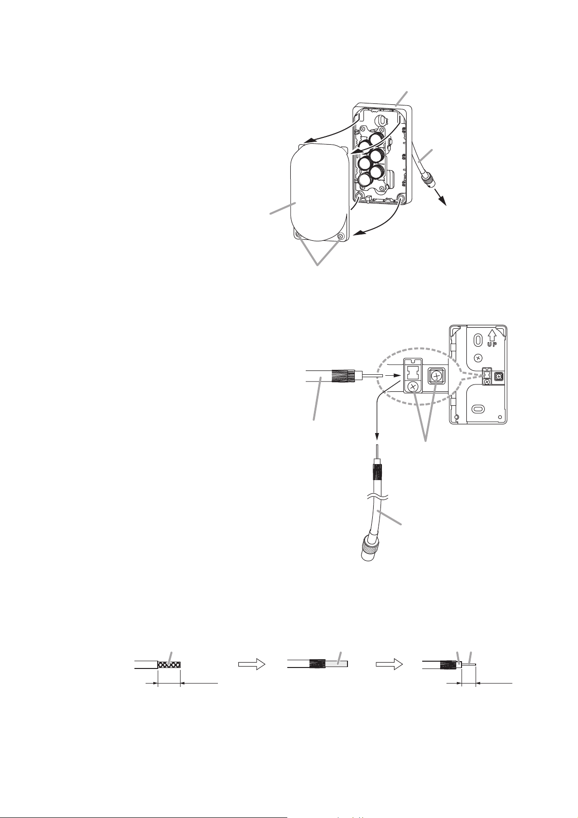
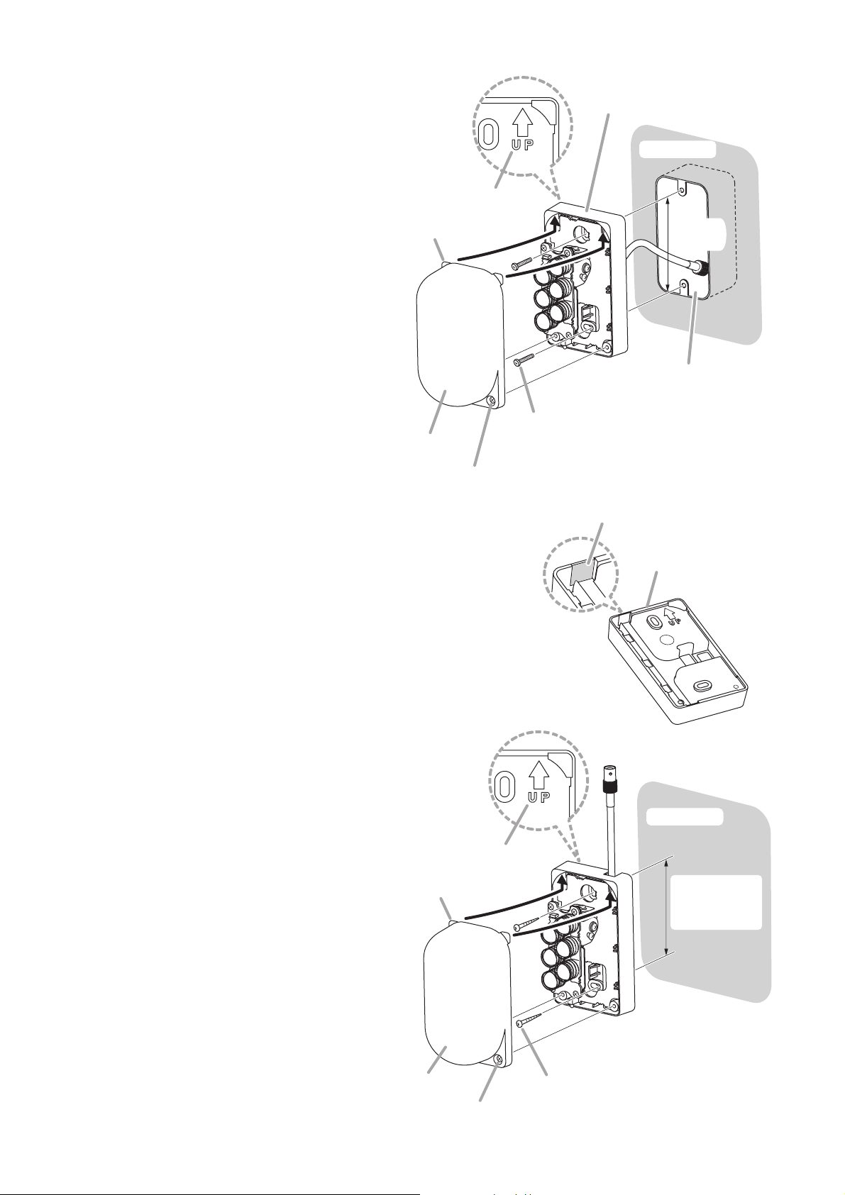
11.1. Wall Mounting
11. INSTALLING THE IR-500R INFRARED WIRELESS RECEIVER
Step 1. Loosen 2 case fixing screws, then detach
the body case with screws.
Note
No need to remove these case fixing
screws.
Step 2. Connect the coaxial cable.
2-1. When using the BNC connector
Connect the BNC cable to the BNC jack
cable connected to the chassis.
Note
Applicable coaxial cable is RG-59/U or
RG-6/U.
2-2. When connecting the coaxial cable directly
(1) Loosen 2 coaxial cable fixing screws
on the chassis, then disconnect the
BNC jack cable.
Strip the jacket 13 mm (0.51")
from the end of the coaxial cable.
Strip the dielectric 10 mm
(0.39") from the cable end.
Unravel the braided shield
and turn it back.
(2) Treat the coaxial cable end.
(3) Insert the end-treated cable, then securely tighten the coaxial cable fixing screws.
Body case
Case fixing screws
(3)
1
Chassis
BNC jack cable
2
-1
To BNC connector
Chassis (rear)
Braided shield Dielectric
End-treated
coaxial cable
(1)
Coaxial cable fixing screws
BNC jack cable
Dielectric
Conductor
13 mm
(0.51")
10 mm
(0.39")
Page 15
15
Step 3. Install the chassis in an electrical box or on a wall.
3-1. When installing in an electrical box
(1) Install the chassis, with its UP mark
facing upward, in an electrical box.
Note
Since no mounting screws are
supplied with the IR-500R, separately
prepare screws that are appropriate
for the electrical box used.
(2) Adjust the reception angle referring
to p. 16 – 17.
(3) Replace the body case by inserting
the tabs on its top into the upper
inside of the chassis, then retighten
the case fixing screws to secure the
body case.
3-2. When directly installing on a wall
(1) Cut out the cable entry tab in the chassis using nippers.
One each of cable entry tabs, which are relatively thin,
is provided in the top and bottom surface of the
chassis. Cut out the entry tab as needed.
(2) Install the chassis, with its UP mark
facing upward, on a wall.
Note
Since no mounting screws are
supplied with the IR-500R, separately
prepare screws that are appropriate
for the construction of wall.
(3) Adjust the reception angle referring
to p. 16 – 17.
(4) Replace the body case by inserting
the tabs on its top into the upper
inside of the chassis, then retighten
the case fixing screws to secure the
body case.
Tabs (2 places)
Body case
Case fixing screw
Chassis
Wall surface
UP mark
83.5 mm
(3.29")
In-wall electrical box
(1-gang)
Mounting screw
(Prepare separately.)
Tabs (2 places)
Cable entry tab
Chassis (rear)
Wall surface
UP mark
Mounting pitch
83.5 mm
(3.29")
Body case
Case fixing screw
Mounting screw
(Prepare separately.)
Page 16
16
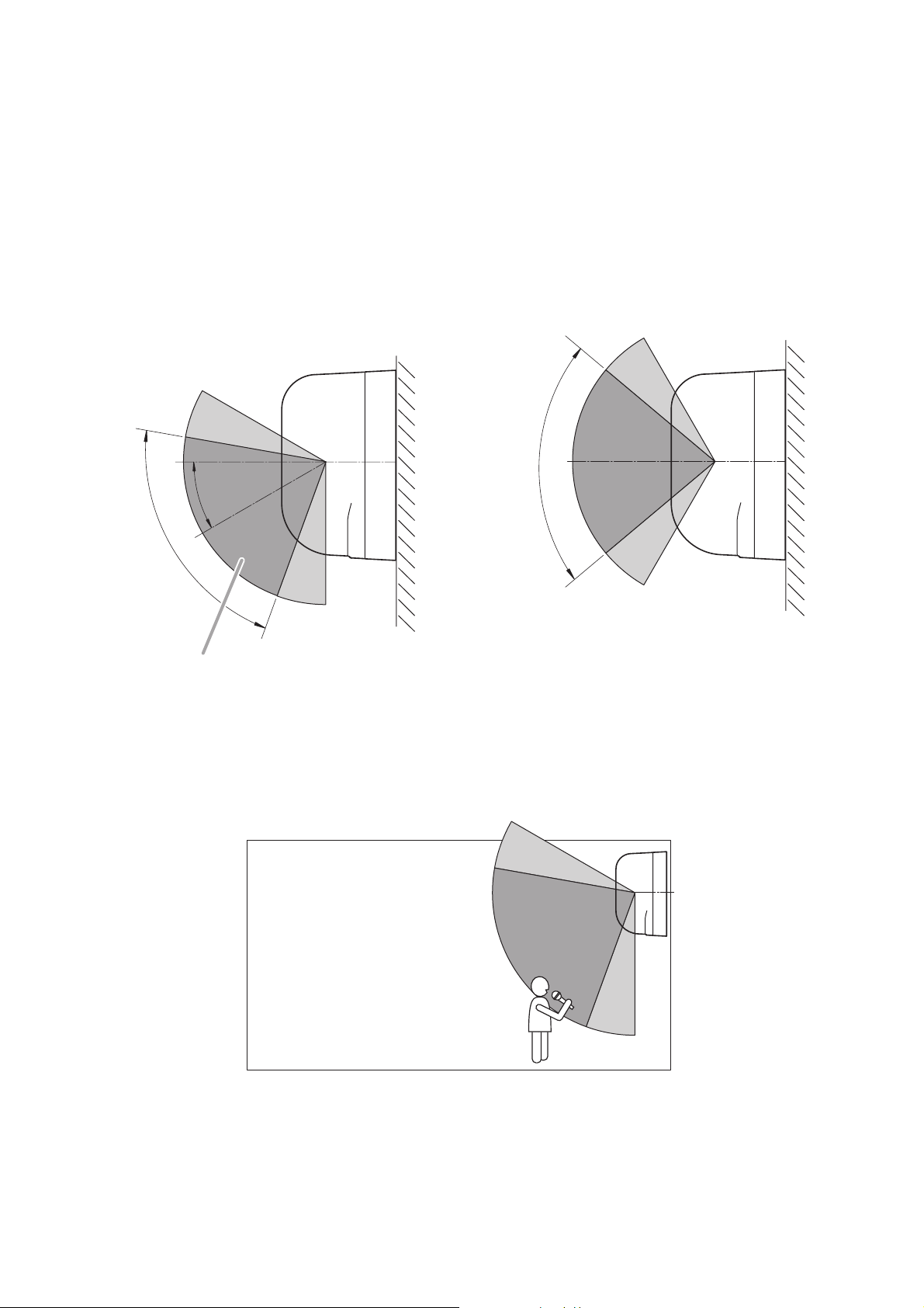
11.2. Adjusting the Reception Angle
Communications area of the IR-500R can be adjusted both vertically (from 0º to approx. 30º downward) and
horizontally (approx. 30º to the right or left) by moving its reception section.
Adjust the angle depending on the installation location.
11.2.1. IR-500R's receiving angle image
[Vertical direction]
(Factory-preset : approx. 30° downward) (When moving the reception section to vertical 0° position)
IR-500R (side view)
Approx. 80°
Approx. 30°
Approx. 80°
High sensitivity area
Adjustment example in vertical direction
(when installing the IR-500R at a higher position)
Page 17
17
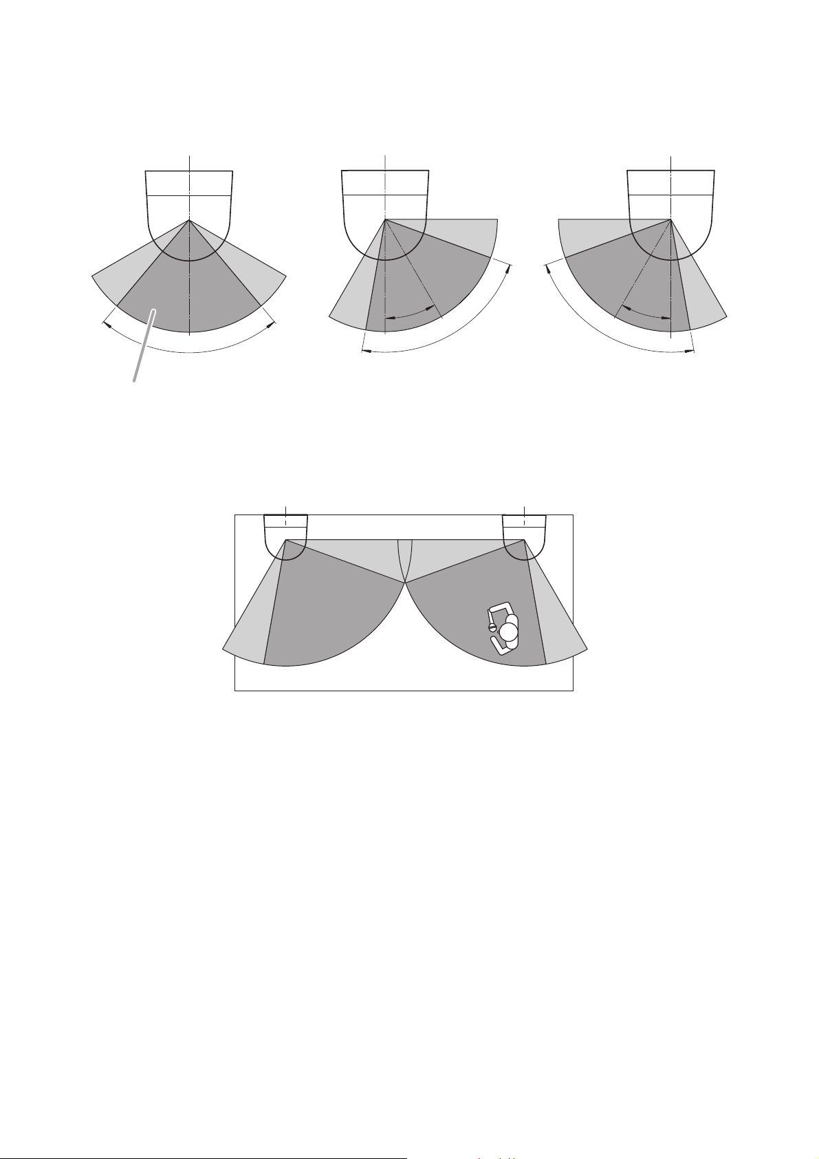
[Horizontal direction]
(Factory-preset) (When moving the reception section
IR-500R
(Top view)
Approx. 80°
High sensitivity area
(When moving the reception section
to approx. 30° in the right direction)
Approx.
30°
Approx. 80°
Adjustment example in horizontal direction
(when installing the IR-500Rs at the corners of the room)
to approx. 30° in the left direction)
Approx.
Approx. 80°
30°
Page 18

18
11.2.3. Correcting the horizontal angle
Step 1. Loosen the reception angle fixing screw (for horizontal).
Step 2. Direct the reception section to the left or right towards the area, where the infrared wireless
microphones are used, by hand.
Step 3. Retighten the loosened screw in Step 1.
11.2.2. Correcting the vertical angle
Step 1. Loosen the reception angle fixing screw (for vertical).
Step 2. Direct the reception section down or up towards the area, where the infrared wireless microphones
are used, by hand.
Step 3. Retighten the loosened screw in Step 1.
Correct the reception section’s vertical angle first, then the horizontal angle.
IR-500R's chassis (side view)
Note
Never loosen this screw.
Reception angle fixing screw
Note
This screw can be removed and
attached to the other side.
Reception section
(Factory-preset)
(Example when tilted upward)
IR-500R's chassis (top view)
Reception angle fixing screw
Note
Never loosen this screw.
Reception section
(Factory-preset) (Example when moved to the left)
Page 19

19
Step 1. Make a mounting hole of 68 mm (2.68") in the ceiling board.
Step 2. Install the mounting plate (supplied with the IR-510R) to the ceiling board.
Notes
• The IR-510R offers a mounting pitch of 83.5 mm (3.29") and can be mounted in an electrical box as
well.
• Use an electrical box in the case of open wiring.
• Use a BNC L connector or an L-shaped adapter connector when mounting the receiver in an
electrical box.
Step 3. After wiring completion, attach the receiver to the mounting plate.
Align the receiver tabs (3 places) with the notches in the plate, then rotate the receiver clockwise to
full stop.
12.1. Ceiling Mounting
12. INSTALLING THE IR-510R INFRARED WIRELESS RECEIVER
Coaxial cable
Tabs (3 places)
IR-510R
Infrared wireless receiver
83.5 mm
(3.29")
3
Installation direction
ø68 ± 5 mm
(ø2.68" ±0.2")
Mounting plate (supplied with the IR-510R)
1
2
Mounting screw
Note
Since no mounting screws are supplied
with the unit, prepare them separately.
Page 20

20
Step 1. Loosen 2 case fixing screws, then detach the body case.
Step 2. Install the chassis to a wall.
Note
Since no mounting screws are supplied with the unit, prepare them separately.
Step 3. Attach the body case to the chassis.
Retighten 2 loosened screws in step 1.
Step 4. Connect the coaxial cable.
13.1. Wall Mounting
13. INSTALLING THE IR-520R INFRARED WIRELESS RECEIVER
Coaxial cable
4
Chassis
Wall surface
62 mm (2.44")
Oval hole
4.5 x 8 mm
(0.18" x 0.31")
2
Mounting screw
(Prepare separately.)
Body case
1, 3
Case fixing screw
Note
No need to remove this case fixing screw.
Page 21

21
Step 1. Attach the stand mounting bracket (supplied with the IR-520R) to a microphone stand.
Applicable screw size: U 5/16
Step 2. Loosen 2 case fixing screws, then detach the body case.
Step 3. Secure the chassis to the stand mounting bracket using 2 machine screws M4 x 10 (supplied with the
IR-520R).
Step 4. Attach the body case to the chassis.
Step 5. Connect the coaxial cable.
Note
For the microphone stand installation, refer to the instruction manual attached to the microphone stand.
13.2. Mounting on a Microphone Stand
Chassis
3
Machine screw M4 x 10
(supplied with the IR-520R)
Body case
Stand mounting bracket
(supplied with the IR-520R)
1
5
2 , 4
Case fixing screw
Note
No need to remove this
case fixing screw.
Microphone stand
Mounting screw: U 5/16
Coaxial cable
Page 22

22
Use the optional MB-WT3 Mounting Bracket when installing the unit in a rack.
Note
For the mounting bracket installation, refer to the instruction manual attached to the MB-WT3.
14.1. Mounting in a Rack
When installing the unit on a desk, secure 4 supplied rubber feet to the unit's bottom.
14.2. Mounting on a Desk
14. INSTALLING THE INFRARED WIRELESS TUNER
Bracket B*
* Component parts of the MB-WT3
Fiber washer (for M5)*
Infrared Wireless Tuner
IR-702T
Rack mounting screw 5 x 12*
Bracket A*
Rubber foot
(supplied with the IR-702T)
IR-702T
bottom surface
Page 23

23
15. INFRARED WIRELESS RECEIVER TO TUNER WIRING
15.1. Wiring Precautions
When multiple infrared wireless receivers have received an infrared signal from the infrared wireless
microphone, the reception level increases if the signals input to each receiver are in phase with each other.
However, the reception level could decrease if the signals are out of phase.
• To match signal phases, make each corresponding cable the following length:
Cable length from each infrared wireless receiver to the tuner: M1 + N1 = M2 + N2
where M1, N1, M2, and N2 are:
M1: Cable length between the receiver (A or A') and distributor 1
N1: Cable length between the distributor 1 and tuner
M2: Cable length between the receiver (B or B') and distributor 2
N2: Cable length between the distributor 2 and tuner
15.2. When Using the Distributor YW-1022/1024
• The YW-1022 is a 2-branch distributor and the YW-1024 is a 4-branch distributor.
• Some idle YW-1024 distribution terminals may result, depending on wiring, however this presents no
problem.
• Avoid connecting 2 or more distributors in series. Connecting them in series increases high-frequency signal
loss, potentially resulting in system malfunctions.
• Assure that all infrared wireless receivers within the same system are connected through the same type of
Distributor. If different types of Distributors are mixed together, or if there are connections both through and
around the Distributor, this can narrow the coverage area.
15.3. When Using the Infrared Wireless Distributor IR-700D
Wiring method for the IR-700D Infrared Wireless Distributor differs from that for the YW-1022 and YW-1024
Distributors. For the wiring method of the system using the IR-700D, refer to the instruction manual enclosed
with the IR-700D.
• The maximum cable length between each Infrared Wireless Receiver and tuner differs depending on the
type of coaxial cable to be used.
Take care not to exceed the maximum cable length. (Refer to p. 10 "Supplementary Remarks.")
Note
When using the Distributors, be sure to
connect the same type of distributor to
the infrared wireless tuner’s receiver
inputs 1 – 2. No problems should result
even if a different number of Infrared
Wireless Receivers are connected to
each Distributor.
Infrared wireless receiver
(A)
Infrared wireless receiver
(A’)
Distributor 1 Distributor 2
Infrared wireless tuner
Infrared wireless receiver
N1 N2
(B)
M2 M2M1 M1
Infrared wireless receiver
(B’)
Page 24

24
[Example 2]
When installing both the infrared wireless receiver and distributor in
the same location, make all "M" distances (cable length between
receiver and distributor) equal.
Notes
• To facilitate unification of coaxial cable lengths, it is
recommended that wiring from the tuner to the ceiling-mounted
distributor should be performed using a single cable.
• The use of coaxial cables cut to an even length that is slightly
longer than required easily makes all "M" distances of wiring in
the ceiling identical.
15.4. Wiring Examples
[Example 1]
When installing multiple infrared wireless receivers in the same
location, make all "N" distances (cable length between receiver
and tuner) equal.
Infrared wireless receiver
Infrared wireless tuner
Infrared wireless receiver
Distributor
M
M
N
NN
M
M
Infrared wireless tuner
Page 25

25
16. SUPPLEMENTARY REMARKS
(How to find a maximum cable length from infrared wireless tuner to receiver)
Cable distance values here are provided merely as a guide, since such values differ depending on the
structure of buildings and environmental conditions of the infrared wireless receiver.
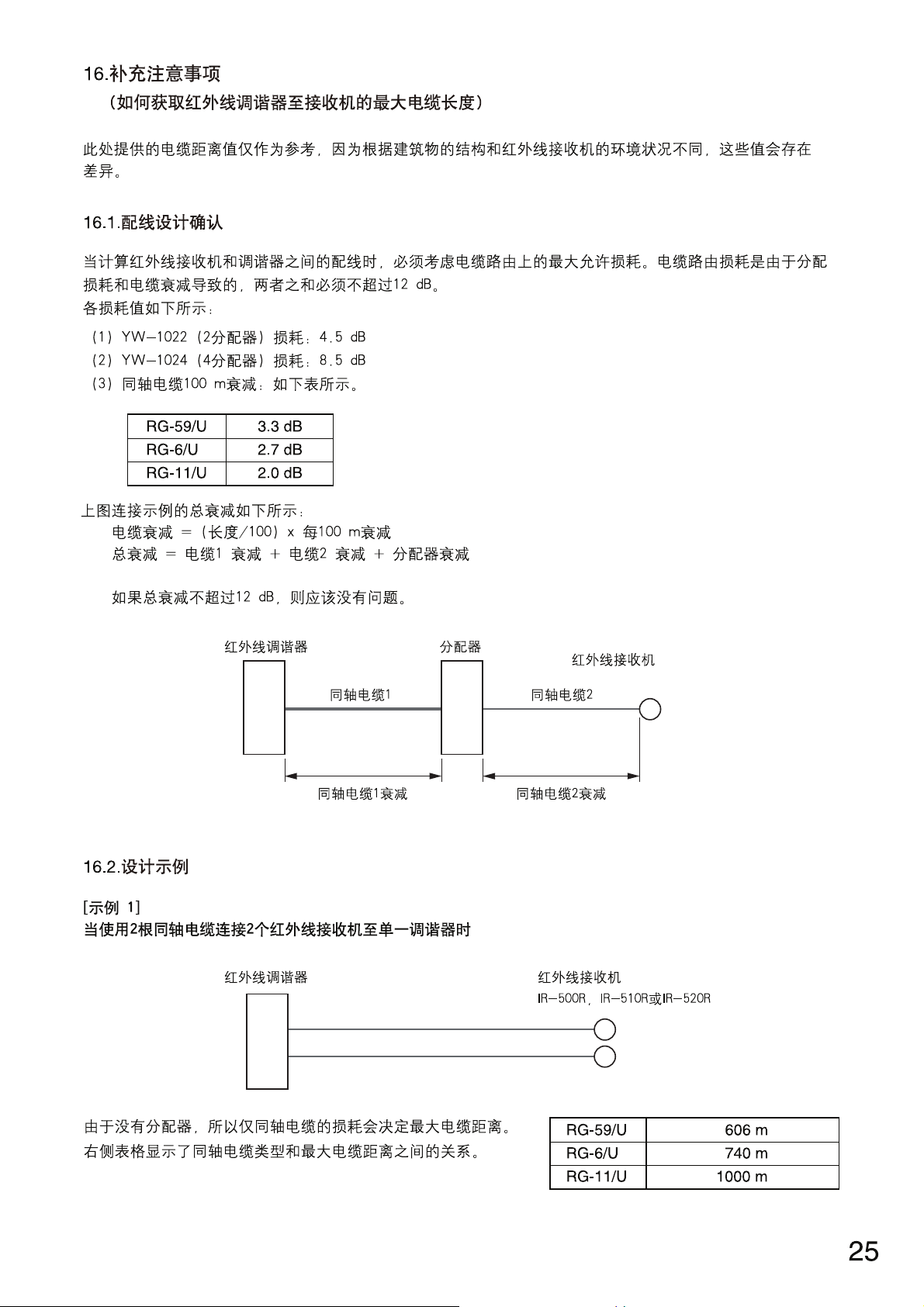
16.1. Wiring Design Confirmation
Maximum permissible loss on cable routing must be taken into consideration when calculating wiring between
infrared wireless receivers and the tuner. The cable routing loss is caused by distribution loss and cable
attenuation, and the sum of both must not exceed 12 dB.
The loss value for each is as follows:
(1) Loss of the YW-1022 (2-branch distributor): 4.5 dB
(2) Loss of the YW-1024 (4-branch distributor): 8.5 dB
(3) Attenuation for 100 m (109.36 yd) of coaxial cable: As shown in the table below.
RG-59/U 3.3 dB
RG-6/U 2.7 dB
RG-11/U 2.0 dB
Total attenuation for the connection example illustrated below is as follows:
Cable attenuation = (length/100) x attenuation per 100 m
Total attenuation = Cable 1 attenuation + Cable 2 attenuation + Distributor's attenuation
If this total attenuation does not exceed 12 dB, then there should be no problem.
16.2. Design Examples
[Example 1]
When connecting 2 infrared wireless receivers to a single tuner using 2 coaxial cables
Because there is no distributor, only the coaxial cable loss
determines the maximum cable distance.
The table at right shows the relationship of coaxial cable type to
maximum cable distance.
RG-59/U 606 m (662.73 yd)
RG-6/U 740 m (809.27 yd)
RG-11/U 1000 m
(1093.61 yd)
Infrared wireless tuner
Coaxial cable 1
Coaxial cable 1 attenuation
Distributor
Infrared wireless receiver
Coaxial cable 2
Coaxial cable 2 attenuation
Infrared wireless tuner Infrared wireless receiver
IR-500R, IR-510R, or IR-520R
Page 26

26
[Example 2]
When connecting 4 infrared wireless receivers to a single tuner using a single coaxial cable
Precondition: Cable distance (L2) from the distributor to the receiver is assumed to be 25 m (27.34 yd).
Assuming that the RG-59/U coaxial cable is used in wiring between the distributor and the receiver, the
attenuation of this distance is:
Attenuation = 3.3 dB x (25 m / 100 m) = 0.825 dB.
Since loss of 8.5 dB results from the distributor, the maximum permissible loss from the infrared wireless tuner
to the distributor stands at 2.675 dB (12 dB – 0.825 dB – 8.5 dB).
If the RG-6/U coaxial cable is used in wiring from the tuner to the distributor, given the wiring distance
between the two is L1,
L1 = (coaxial cable attenuation/coaxial cable attenuation per 100 m)
= (2.5 dB / 2.7 dB) x 100 m
= 92 m (100.61 yd)
Maximum cable length (wiring distance from the infrared wireless tuner to the infrared wireless receiver) can
be found from the following equation:
L = L1 + 25 m
= 92 m + 25 m
= 117 m (127.95 yd)
Similarly, the maximum cable length (wiring distance from the tuner to the receiver) calculated relative to the
type of coaxial cable used between the tuner and the distributor is as shown in the table below:
RG-59/U 348 m (380.58 yd)
RG-6/U 414 m (452.76 yd)
RG-11/U 542 m (592.74 yd)
Infrared wireless tuner Infrared wireless receiverDistributor
L1 25 m or 27.34 yd (L2)
L
Page 27

27
17. TROUBLESHOOTING
Symptom
The unit fails to turn on
when the power switch is
pressed.
Cause and Points to Check
Power plug is unplugged from an
AC wall outlet.
Remedy
Plug the power plug into an AC wall
outlet.
No signal received
Infrared wireless microphone's
battery has become discharged.
Replace the battery with a new one.
If a rechargeable battery is used,
recharge it.
Sound is too faint to hear
Amplifier volume control is set to too
low a level.
Set the amplifier volume control to an
appropriate volume level.
Infrared wireless microphone's
power switch not set to ON.
Set the microphone power switch to
ON.
The channel set for the infrared
wireless microphone differs from the
receiving channel.
Make both the infrared microphone
and reception channels identical.
Infrared wireless tuner's volume
control is set to too low a level.
Rotate the tuner's volume control to
set it to an appropriate volume level.
No sound outputs Infrared wireless tuner not
connected to an amplifier properly.
Connect correctly.
(See p. 9 "Connection Example.")
CH-A/MIX output selector switch not
set correctly.
Set the switch correctly.
(See p. 9 "Connection Example.")
Noise or strange (i.e. muddy)
sound is heard
Infrared wireless receiver is installed
in close proximity to a device
generating radio noise or infrared
light.
Set the receiver properly, referring to
p. 11 "Installation precautions" for the
infrared wireless receiver.
Short transmission distance Infrared wireless receiver cables not
properly connected.
Connect the receiver cables properly.
Page 28

*1 0 dB = 1 V
*
2
Not supplied with the IR-702T KR. For the usable power supply cord and AC adapter, contact your nearest
TOA dealer.
URL: http://www.toa.jp/
18. SPECIFICATIONS
Note: The design and specifications are subject to change without notice for improvement.
• Accessories
Power Source AC mains, 50/60 Hz (supplied from the included AC adapter)
Power Consumption 15 W or less
Receiving Frequency Channel A: 3.100 MHz
Channel B: 3.350 MHz
Receiver Sensitivity S/N ratio: over 50 dB (40 dBμV input, 1 kHz modulation, ±4.8 kHz deviation)
S/N ratio 61 dB or more (60 dBμV input, ±4.8 kHz deviation, A-weighted)
Tone squelch frequency 32.768 kHz
Infrared Receiver Input 75 Ω, BNC jack x 2 (Infrared wireless receiver's power source: 24 V DC,
220 mA max. in total of 2 terminals)
Output Channel A and B: –10 dB*1(±4.8 kHz deviation, at volume level max.), 600 Ω,
electronically balanced, 3 pole phone jack
Note: Channel A switchable to mixer output
Frequency Response 100 Hz – 12 kHz
Operating Temperature –10 to +50 °C (+14 to +122 °F)
Operating Humidity 30 to 85% RH
Finish Case: ABS resin, black
Dimensions 210 (w) x 44 (h) x 210.9 (d) mm (8.27" x 1.73" x 8.3")
Weight 630 g or 1.39 lb (unit itself)
AC adapter
*
2
..................................................... 1
Power cord (2 m or 6.56 ft)
*
2
............................. 1
Cord with a phone plug (1 m or 3.28 ft) ............ 1
Color label (6 colors) ......................................... 1
Rubber foot ....................................................... 4
• Optional product
Rack mounting bracket: MB-WT3
Traceability Information for Europe (EMC directive 2004/108/EC)
Manufacturer:
TOA Corporation
7-2-1, Minatojima Nakamachi, Chuo-ku, Kobe, Hyogo,
Japan
Authorized representative:
TOA Electronics Europe GmbH
Suederstrasse 282, 20537 Hamburg,
Germany
Page 29

Page 30

Page 31

Page 32

Page 33

Page 34

Page 35

Page 36

Page 37

Page 38

Page 39

Page 40

Page 41

Page 42

Page 43

Page 44

Page 45

Page 46

Page 47

Page 48

Page 49

Page 50

Page 51

Page 52

Page 53
Page 54

Page 55

Page 56

 Loading...