

Page 1
OPERATING INSTRUCTIONS
INFRARED WIRELESS DISTRIBUTOR
IR-700D
Thank you for purchasing TOA's Infrared Wireless Distributor.
Please carefully follow the instructions in this manual to ensure long, trouble-free use of your equipment.
Page 2

2
TABLE OF CONTENTS
1. SAFETY PRECAUTIONS ...................................................................................... 3
2. GENERAL DESCRIPTION ................................................................................... 4
3. HANDLING PRECAUTIONS ................................................................................ 4
4. NOMENCLATURE AND FUNCTIONS
Front ............................................................................................................................... 4
Rear ............................................................................................................................... 4
5. SYSTEM CONFIGURATION EXAMPLE .......................................................... 5
6. CONNECTION EXAMPLE .................................................................................... 6
7. INSTALLATION
7.1. Mounting a Single Unit in an Equipment Rack ........................................................ 7
7.2. Mounting in Conjunction with the IR-702T in an Equipment Rack .......................... 7
7.3. Mounting on a Desk ................................................................................................ 7
8. WIRING TO INFRARED WIRELESS RECEIVER
8.1. Wiring Precautions .................................................................................................. 8
8.2. When Using the Distributor YW-1022/1024 ............................................................ 8
8.3. Wiring Examples ..................................................................................................... 9
9. SUPPLEMENTARY REMARKS
9.1. Wiring Design Confirmation .................................................................................. 10
9.2. Design Examples .................................................................................................. 10
10. SPECIFICATIONS ................................................................................................. 12
Accessories .................................................................................................................. 12
Optional products ......................................................................................................... 12
This device complies with Part 15 of the FCC Rules. Operation is subject to the following two conditions:
(1) this device may not cause harmful interference, and
(2) this device must accept any interference received, including interference that may cause undesired
operation.
Any modifications made to this device that are not approved by TOA Corporation may void the authority
granted the user by the FCC to operate this equipment.
FCC Compliance
Page 3
3
When Installing the Unit
• Do not expose the unit to rain or an environment
where it may be splashed by water or other liquids,
as doing so may result in fire or electric shock.
• Use the unit only with the voltage specified on the
unit. Using a voltage higher than that which is
specified may result in fire or electric shock.
• Do not cut, kink, otherwise damage nor modify the
power supply cord. In addition, avoid using the
power cord in close proximity to heaters, and never
place heavy objects -- including the unit itself -- on
the power cord, as doing so may result in fire or
electric shock.
When the Unit is in Use
• Should the following irregularity be found during
use, immediately switch off the power, disconnect
the power supply plug from the AC outlet and
contact your nearest TOA dealer. Make no further
attempt to operate the unit in this condition as this
may cause fire or electric shock.
· If you detect smoke or a strange smell coming
from the unit.
· If water or any metallic object gets into the unit
· If the unit falls, or the unit case breaks
· If the power supply cord is damaged (exposure of
the core, disconnection, etc.)
· If it is malfunctioning (no tone sounds.)
• To prevent a fire or electric shock, never open nor
remove the unit case as there are high voltage
components inside the unit. Refer all servicing to
qualified service personnel.
• Do not place cups, bowls, or other containers of
liquid or metallic objects on top of the unit. If they
accidentally spill into the unit, this may cause a fire
or electric shock.
• Do not touch a power supply plug during thunder
and lightning, as this may result in electric shock.
When Installing the Unit
• Never plug in nor remove the power supply plug
with wet hands, as doing so may cause electric
shock.
• When unplugging the power supply cord, be sure
to grasp the power supply plug; never pull on the
cord itself. Operating the unit with a damaged
power supply cord may cause a fire or electric
shock.
• When moving the unit, be sure to remove its power
supply cord from the wall outlet. Moving the unit
with the power cord connected to the outlet may
cause damage to the power cord, resulting in fire or
electric shock. When removing the power cord, be
sure to hold its plug to pull.
• Avoid installing the unit in humid or dusty locations,
in locations exposed to the direct sunlight, near the
heaters, or in locations generating sooty smoke or
steam as doing otherwise may result in fire or
electric shock.
• Refer all installation work to the dealer from where
the unit was purchased. Installation requires
extensive technical knowledge and experience.
Improper installation may result in personal injury
or electric shock.
When the Unit is in Use
• Use the AC adapter supplied with the unit. Note
that the use of other adapter may cause a fire.
• If dust accumulates on the power supply plug or in
the wall AC outlet, a fire may result. Clean it
periodically. In addition, insert the plug in the wall
outlet securely.
• Switch off the power, and unplug the power supply
plug from the AC outlet for safety purposes when
cleaning or leaving the unit unused for 10 days or
more. Doing otherwise may cause a fire or electric
shock.
WARNING CAUTION
1. SAFETY PRECAUTIONS
• Before installation or use, be sure to carefully read all the instructions in this section for correct and safe
operation.
• Be sure to follow all the precautionary instructions in this section, which contain important warnings and/or
cautions regarding safety.
• After reading, keep this manual handy for future reference.
Indicates a potentially hazardous situation which, if mishandled, could
result in death or serious personal injury.
Indicates a potentially hazardous situation which, if mishandled, could
result in moderate or minor personal injury, and/or property damage.
WARNING
CAUTION
Page 4
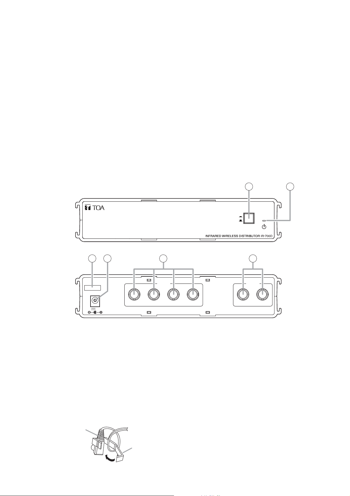
1. Power switch
Press this switch to turn on the power.
To turn off the power, press this switch again.
2. Power indicator
Lights when the power is switched on.
3. Cable Clip
Run the AC adapter cable through this clip to
prevent its plug from being removed.
4. DC inlet [DC IN]
Connect the supplied AC adapter.
5. Receiver mixing input terminals [IR IN]
Connect the infrared wireless receiver or the
distributor.
Up to 8 infrared wireless receivers can be
connected with the use of the optional YW-1022
(2-Branch Distributor) or the YW-1024 (4-Branch
Distributor).
6. Distribution output terminals [IR OUT]
Connect the IR-702T Infrared Wireless Tuner.
4
2. GENERAL DESCRIPTION
The IR-700D is a receiver distributor used in the TOA’s infrared wireless microphone system.
It employs 4 receiver mixing inputs and 2 distribution outputs.
By using the IR-700D in conjunction with the IR-702T Infrared Wireless Tuner, up to 16 infrared wireless
receivers can be connected to the IR-702T.
3. HANDLING PRECAUTIONS
• Install the IR-702T as far as possible from fluorescent lights, digital equipment, PCs and other devices that
generate high-frequency noise.
• When cleaning, be sure to first switch off the tuner's power, then wipe with a dry cloth. If the tuner is
extremely dirty, use a cloth moistened in a neutral detergent. Do not use benzene, thinner, alcohol and
chemically-processed towels, as they can cause damage to the tuner's components and parts.
4. NOMENCLATURE AND FUNCTIONS
1 2
[Front]
3 4 5 6
[Rear]
DC IN
24V 1A(max)
IR IN
75 Ω
213
ON
OFF
POWER
IR OUT
124
AC adapter plug
Cable clip
Page 5

5
5. SYSTEM CONFIGURATION EXAMPLE
Infrared Wireless Tuner
IR-702T
Infrared Wireless Distributor
IR-700D
Infrared Wireless Receiver
IR-500R, IR-510R, or
IR-520R
Note
Connect one IR-500R, IR-510R, or IR-520R Infrared Wireless Receiver
to each of the IR-700D’s receiver mixing input terminals 1 to 4.
Infrared Wireless Microphone
IR-200M
Infrared Wireless Microphone
IR-300M
Page 6

6
6. CONNECTION EXAMPLE
Combining the IR-700D with the IR-702T tuner allows the number of the infrared wireless receivers connected
to the IR-702T to be increased.
The connection example shown below is a system having 5 or more receivers to be connected to the IR-702T
tuner.
Distributor
YW-1024 (4-branch distributor)
or
YW-1022 (2-branch distributor)
Infrared Wireless Receiver
IR-500R, IR-510R, or IR-520R
IR IN
75 Ω
DC IN
24V 1A(max)
213
Infrared Wireless Distributor
IR-700D
124
IR OUT
IR IN OUTPUT
75 Ω
DC IN
24V 0.6A(max)
12
BNC plug-to-BNC plug cord
(supplied with the IR-700D)
–10dBV/600Ω
CH B
CH A/MIX
CH A
MIX
Infrared Wireless Tuner
IR-702T
Page 7

7
7.1. Mounting a Single Unit in an Equipment Rack
Use the optional MB-WT3 Mounting Bracket to mount a single IR-700D unit.
Note: For the mounting bracket installation, refer to the instruction manual attached to the MB-WT3.
7.2. Mounting in Conjunction with the IR-702T in an Equipment Rack
Use the optional MB-WT4 Rack Mounting Bracket.
Note: For the MB-WT4 installation, refer to the instruction manual attached to the MB-WT4.
7.3. Mounting on a Desk
When installing the unit on a desk,
secure 4 supplied rubber feet to the unit's
bottom.
7. INSTALLATION
*1 Component parts of the MB-WT3
IR-700D
Bracket B*
Fiber washer (for M5)*
Rack mounting screw 5 x 12*
1
1
1
Bracket A*
1
*2 Component parts of the MB-WT4
IR-702T
IR-700D
Fiber washer (for M5)*
2
Rack mounting screw 5 x 12*
2
Connector*
2
IR-700D
bottom surface
Bracket*
2
Rubber foot
(supplied with the IR-700D)
Page 8

8
8. WIRING TO INFRARED WIRELESS RECEIVER
8.1. Wiring Precautions
When multiple infrared wireless receivers have received an infrared signal from the infrared wireless
microphone, the reception level increases if the signals input to each receiver are in phase with each other.
However, the reception level could decrease if the signals are out of phase.
• To match signal phases, make each corresponding cable the following length:
Cable length from each infrared wireless receiver to the IR-700D : M1 + N0 = N1
where M1, N0, and N1 are:
M1: Length between Infrared wireless receiver (A or A’) and YW-1022/1024 Distributor
N0: Length between YW-1022/1024 Distributor and IR-700D
N1: Length between Infrared wireless receiver (B) and IR-700D
8.2. When Using the Distributor YW-1022/1024
• The YW-1022 is a 2-branch distributor and the YW-1024 is a 4-branch distributor.
• Some idle YW-1024 distribution terminals may result, depending on wiring, however this presents no
problem.
• Avoid connecting 2 or more distributors in series. Connecting them in series increases high-frequency signal
loss, potentially resulting in system malfunctions.
• Even if a system includes infrared wireless receivers connected to the tuner via a distributor and those
directly connected to the tuner, this presents no problem.
• The maximum cable length between each Infrared Wireless Receiver and IR-700D differs depending on the
type of coaxial cable to be used.
Take care not to exceed the maximum cable length. (Refer to p. 10 "Supplementary Remarks.")
Infrared wireless receiver
Infrared wireless receiver
(A)
Infrared wireless receiver
(A’)
Distributor
YW-1022/1024
M1M1
(B)
N0 N1
Infrared wireless tunerInfrared wireless distributor
IR-700D
BNC plug-to-BNC plug cord (supplied with the IR-700D)
Page 9

9
[Example 2]
When installing both the infrared wireless receiver and distributor in the same location, make all "M" distances
(cable length between receiver and distributor YW-1022/1024) equal.
Notes
• To facilitate unification of coaxial cable lengths, it is recommended that wiring from the IR-700D to the
distributor YW-1022/1024 should be performed using a single cable.
• The use of coaxial cables cut to an even length that is slightly longer than required easily makes all "M"
distances of wiring in the ceiling identical.
8.3. Wiring Examples
[Example 1]
When installing multiple infrared wireless receivers in the same location, make all "N" distances (cable length
between receiver and IR-700D) equal.
Infrared wireless receiver
NN
Infrared wireless tunerInfrared wireless distributor
IR-700D
BNC plug-to-BNC plug cord (supplied with the IR-700D)
Infrared wireless receiver
Distributor YW-1022/1024
M
M
N
M
M
IR-700D
BNC plug-to-BNC plug cord (supplied with the IR-700D)
Infrared wireless tunerInfrared wireless distributor
Page 10

10
9. SUPPLEMENTARY REMARKS
(How to find a maximum cable length from IR-700D to receiver)
Cable distance values here are provided merely as a guide, since such values differ depending on the
structure of buildings and environmental conditions of the infrared wireless receiver.
9.1. Wiring Design Confirmation
Maximum permissible loss on cable routing must be taken into consideration when calculating wiring between
infrared wireless receivers and the tuner. The cable routing loss is caused by distribution loss and cable
attenuation, and the sum of both must not exceed 12 dB.
The loss value for each is as follows:
(1) Loss of the YW-1022 (2-branch distributor): 4.5 dB
(2) Loss of the YW-1024 (4-branch distributor): 8.5 dB
(3) Attenuation for 100 m (109.36 yd) of coaxial cable: As shown in the table below.
Note: The IR-700D causes no distribution loss.
RG-59/U 3.3 dB
RG-6/U 2.7 dB
RG-11/U 2.0 dB
Total attenuation for the connection example illustrated below is as follows:
Cable attenuation = (length/100) x attenuation per 100 m
Total attenuation = Cable 1 attenuation + Cable 2 attenuation + YW-1022/1024 distributor's attenuation
If this total attenuation does not exceed 12 dB, then there should be no problem.
9.2. Design Examples
[Example 1]
When connecting 2 infrared wireless receivers to a single tuner using 2 coaxial cables
Because no distribution loss is caused by the IR-700D, only the
coaxial cable loss determines the maximum cable distance.
The table at right shows the relationship of coaxial cable type to
maximum cable distance.
RG-59/U 606 m (662.73 yd)
RG-6/U 740 m (809.27 yd)
RG-11/U 1000 m
(1093.61 yd)
Infrared wireless distributor
IR-700D
BNC plug-to-BNC plug cord
(supplied with the IR-700D)
Coaxial cable 1 Coaxial cable 2
Coaxial cable 1 attenuation Coaxial cable 2 attenuation
Distributor
YW-1022/1024
Infrared wireless receiverInfrared wireless tuner
Infrared wireless tuner
Infrared wireless distributor
IR-700D
Infrared wireless receiver
IR-500R or IR-510R
BNC plug-to-BNC plug cord (supplied with the IR-700D)
Page 11

11
[Example 2]
When connecting 4 infrared wireless receivers to a single tuner using a single coaxial cable
Precondition: Cable distance (L2) from the distributor YW-1024 to the receiver is assumed to be 25 m (27.34 yd).
Assuming that the RG-59/U coaxial cable is used in wiring between the YW-1024 and the receiver, the
attenuation of this distance is:
Attenuation = 3.3 dB x (25 m / 100 m) = 0.825 dB.
Since loss of 8.5 dB results from the YW-1024, the maximum permissible loss from the IR-700D to the YW1024 stands at 2.675 dB (12 dB – 0.825 dB – 8.5 dB).
If the RG-6/U coaxial cable is used in wiring from the IR-700D to the YW-1024, given the wiring distance
between the two is L1,
L1 = (coaxial cable attenuation/coaxial cable attenuation per 100 m)
= (2.5 dB / 2.7 dB) x 100 m
= 92 m (100.61 yd)
Maximum cable length (wiring distance from the IR-700D to the infrared wireless receiver) can be found from
the following equation:
L = L1 + 25 m
= 92 m + 25 m
= 117 m (127.95 yd)
Similarly, the maximum cable length (wiring distance from the IR-700D to the receiver) calculated relative to
the type of coaxial cable used between the IR-700D and the YW-1024 is as shown in the table below:
RG-59/U 348 m (380.58 yd)
RG-6/U 414 m (452.76 yd)
RG-11/U 542 m (592.74 yd)
Infrared wireless distributor
IR-700D
L1 25 m or 27.34 yd (L2)
BNC plug-to-BNC plug cord
(supplied with the IR-700D)
Distributor
YW-1024
L
Infrared wireless receiverInfrared wireless tuner
Page 12

133-07-276-9A
URL: http://www.toa.jp/
10. SPECIFICATIONS
Note: The design and specifications are subject to change without notice for improvement.
• Accessories
Power Source AC mains, 50/60 Hz (supplied from the included AC adapter)
Power Consumption 25 W or less
Input/Output 4 mixing inputs, 2 distribution outputs
Band-Pass Frequency 3.0 – 6.0 MHz
Gain 0 dB (±3 dB)
Infrared Receiver Input 75 Ω, BNC jack x 4 (Infrared wireless receiver's power source: 24 V DC,
800 mA max. in total of 4 terminals)
Distribution Output 75 Ω, BNC jack
Operating Temperature –10 to +50 °C (+14 to +122 °F)
Operating Humidity 30 to 85% RH
Finish Case: ABS resin, black
Dimensions 210 (w) x 44 (h) x 200.9 (d) mm (8.27" x 1.73" x 7.91")
Weight 640 g or 1.41 lb (unit itself)
AC adapter* ............................................................... 1
BNC plug-to-BNC plug cord (50 cm or 1.64 ft) .......... 1
Rubber foot ............................................................... 4
• Optional products
Rack mounting bracket: MB-WT3
Rack mounting bracket: MB-WT4
Traceability Information for Europe (EMC directive 2004/108/EC)
Manufacturer:
TOA Corporation
7-2-1, Minatojima Nakamachi, Chuo-ku, Kobe, Hyogo,
Japan
Authorized representative:
TOA Electronics Europe GmbH
Suederstrasse 282, 20537 Hamburg,
Germany
* Not supplied with the IR-702T KR. For the usable power supply cord and AC adapter, contact your nearest
TOA dealer.
 Loading...