

Page 1
User’s Manual
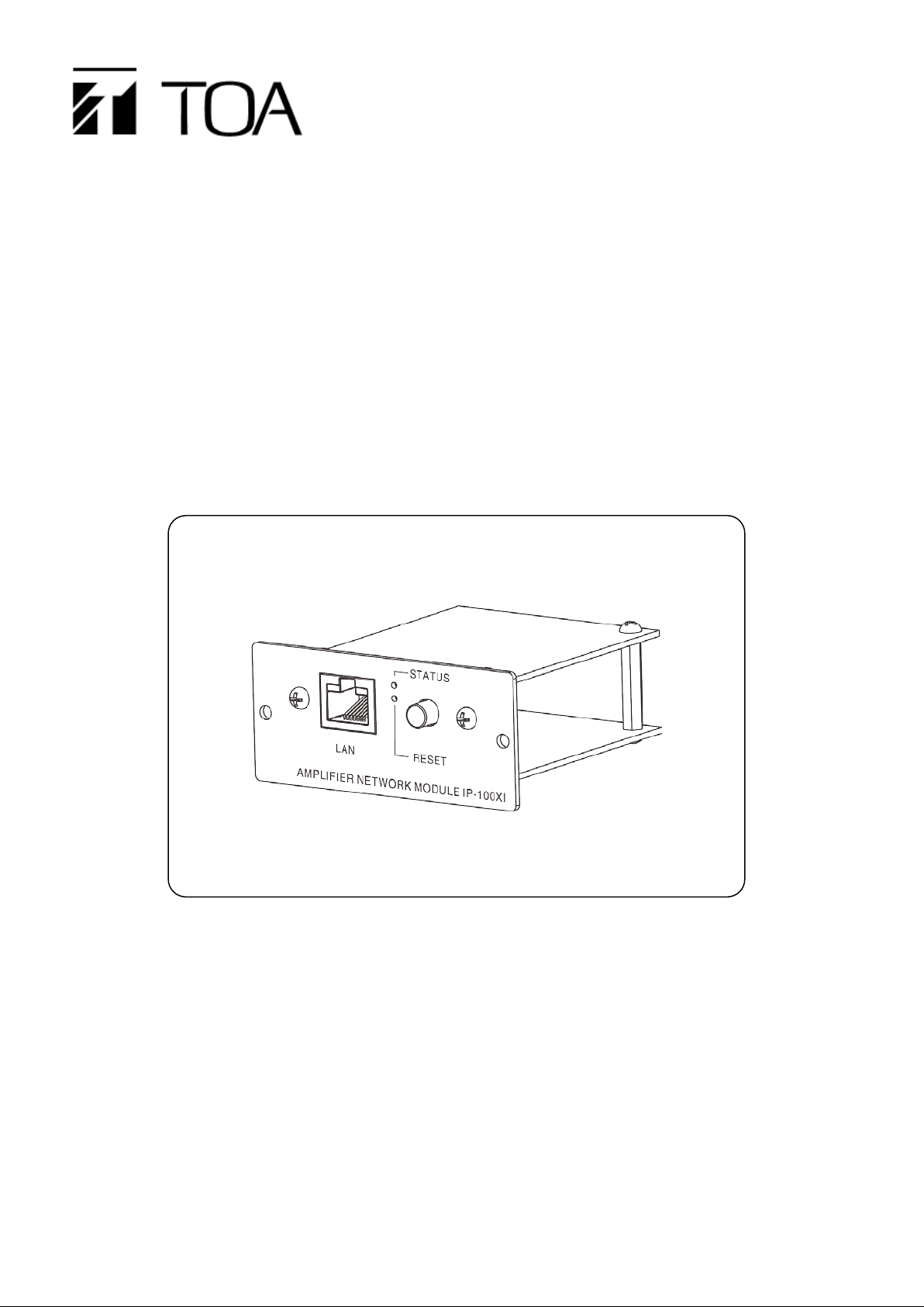
Power Amplifier Network Module IP-100XI
Thanks for your purchase of TOA products IP-1000 series.
Please read the manual carefully to ensure the machine operating in long time and fault-free.
TOA Coporation
Page 2

Chapter 1
Safety Precaution
Page 3

Chapter 1: safety precaution
Please abide by the warning and t he r elevant safety tips.
Please take this manu al i n convenient place aft er you reading the guide for future reference.
Warning
The sign means there is potential safety hazard, when operate wrong may result in
death or serious injury.
The sign is used to remind the user that attached is the important operation and
maintenance data.
(1)Avoid getting t he device wet.
Do not make the machine wet or expose to rain water or other liquid contamination of the
environment, or lead to fir e or get an electric shock.
(2)Do not use unspecified voltage.
Using the marked voltage on the machine.
Using more than the logo of voltage cou ld lead to fire or shock.
(3)Do not scratch the power cor d.
Do not scratch the power cord or cut it.
Simultaneously, keep the power line far way from heated objects, put heavy things on it will lead to
fires or electric shock.
Using machine
(1)In case of the anomalies
Please turn off the power supply immediately when finding the abnormal phenomena, please
connect with the agency. If y ou continue to u sing the equipme nt, it is likely to cat ch on fire or resulte d
in electric shock.
·The smoke or smell of the machine.
·The inside of the machine is floo ded by water or external intrusion.
·Machine falling or machine case damage.
·The power cord damage (wire core is exposed of brok en, et c)
·Malfunction (e.g. no net w or k c onnection, no sound etc. )
(2)Do not open the machin e internal or modify the machine.
Do not external subst ance getting into the equipm ent.
Please do not put any metallic or inflam mab le objects into the machine, otherwise it may cause fires
or electric shock.
(3)Please do not touch it durin g t hundering
To avoid electric shock, please do not t ouch the machine and the plug during lightning, etc.
(4)Please do not place containers with liquid or small metal objects on the machine above.
If containers drop and liquid get into to the machine that will likely cat ch fires or cause elect ric shock.
(5)Do not open the machin e internal or modify the machine.
The machine internal cont ains high volt age p art s, on ce open the c over or mo dify the m achine, it may
result in fires or cause shock. All the maintenance and other machine modification should be
operated by professiona l personnel.
(6)Maintenance and the precautions for not using in a l ong t i m e.
While maintenance, if the m achine is not been used for 10 days or more, please turn off power
supply switch for safety. If do not comply with this provision, it will li kely cause electr ic shoc k or fires .
1-1
Page 4

Chapter 2
Products Description
Page 5

Chapter 2: Products Description
2.1Summary
2.1Summary
IP-100XI is a power amplifier network module, which can be installed in the specific amplifier product to add
in the network functions, it can receive broadcast from other terminals and servers and it supports system
setting via browser.
Receiving broadcast
The IP power amplifier module can receive broadcast from other terminals and servers.
Timing program
Uploading every day sound source to the server, programming the broadcasting plan, the IP power
amplifier module can broadcast the server configuration plan automatically.
Broadcasting IP
When the amplifier module is connected to power but not the LAN cable, pressing the reset button
quickly will automatically broadcasting the IP and subnet mask param et er s in formation.
System setting via browser
User can set network and audio parameters, modify login password via browser to realize the
customized configurati on.
Amplifier protection and amplifier failure information feedback.
Power amplifier network module can receive input information of amplifier protection and failure, the
server will be synchroniz ed window display information of amplifier protection or fau lt .
2-1
Page 6
Chapter 2: Products Description
Status
Operation
Restore IP address
Connect to power, pressing the key for 3 sec
Connect to power but not connecting LAN
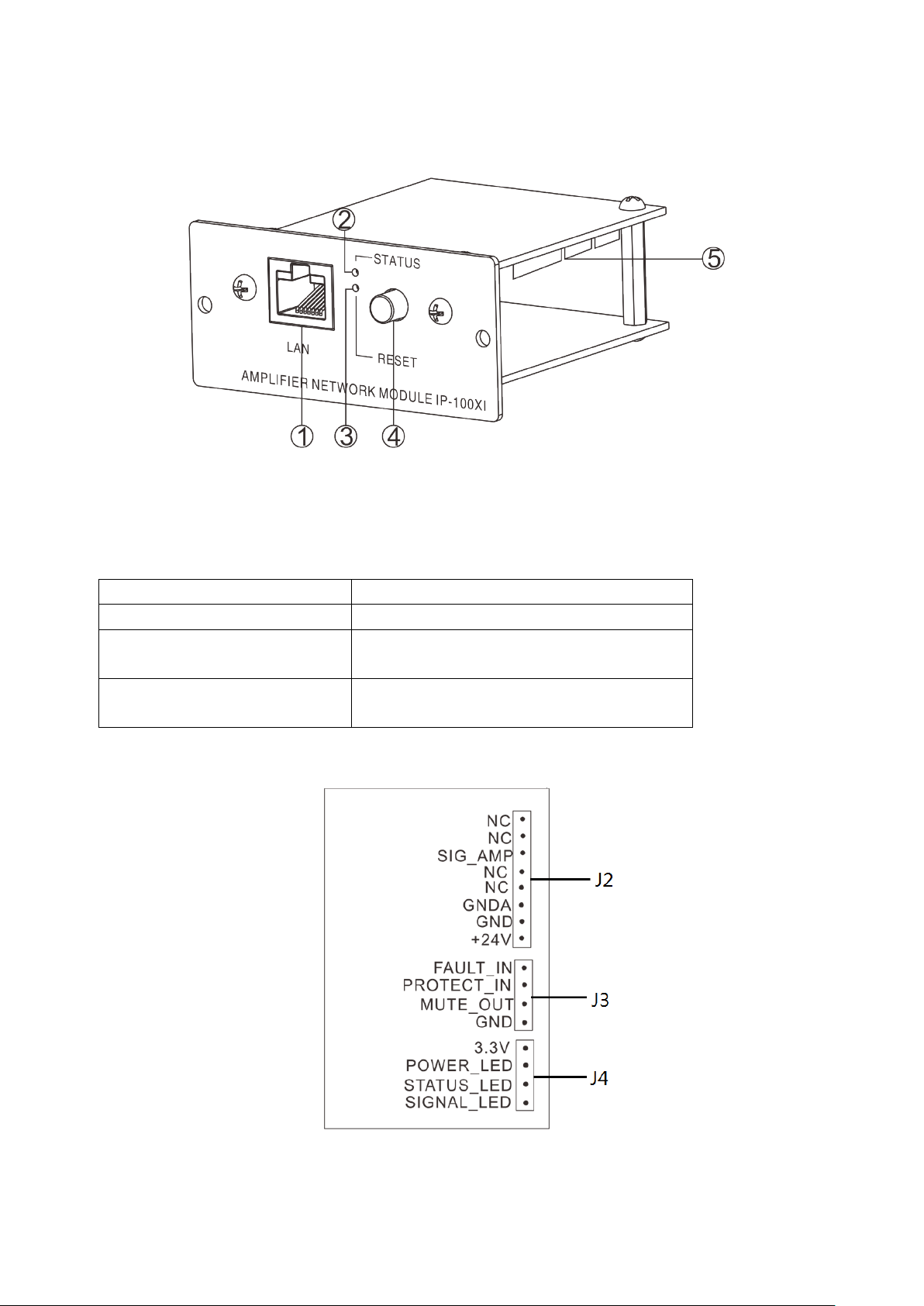
2.2 Interface Description
①LAN: network interface
②STATUS: status indicator light
Online: the green light always be ON; Offline: the red light flash slowly; Receiving broadcast: the gr een
light flash quickly; Updating firmware: both green an d r ed light are flash quickly.
③RESET: pressing the key to restore factory defaults IP (or updat e f irmware), broadcasting IP.
Enter into the update firmw are
page.
Broadcasting IP
Press the key for 5 seconds, then con nect
the power
cable, short pressing and r eleasing.
④VOLUME knob: controls input volume.
⑤Internal interface: the aiagram as follows:
2-2
Page 7

Chapter 2: Products Description
Interface
Remarks
Description
GND
Reference to the control signal
The max electric current: 10mA, the max withstand voltage: DC24V.
open circuit voltage:3. 3V, 10K resistance up to 3.3V.
STATUS_LED
Stat us light inter face, offline is for light OFF, login is for light ON.
SIGNAL_LED
The interface of signal ind i cator light
2.2 Interface description
+24V
J2
J3
J4
Amplifier failure and protection
PROTECT and G ND c an receive amplifier protection information and it wil l send to the server.
Server will pop up a page and display the amplifier prot ec t ion information after t he am plifier protection signal
well received.
Amplifier failure detection
FA U LT_IN and GND can receive a m pl if ier f ai lure detection signal and it will send to the server.
After receiving the a mp l if i er pr ot ect ion information, the server w ill pop up a page and display the amplifier
failure detection infor mati on.
Mute control
MUTE_OUT and GN D can output the mute signal to other m odules or terminals.
The power amplifier networ k m odule output the mute control s ignal in the broadcasting, no mute contro l
signal output in free status.
GND Reference to the power input
GNDA Reference to the audio signal
SIG_AMP Amplifier audio signal input,1Vrms/600Ω, imbalance.
MUTE_OUT
PROTECT_IN
FAULT_IN
3.3V 3.3V interface of power in dicat or light
POWER_LED The interface of power indicat or light
Power input, nominal inpu t DC2 4V/ 150mA,the maximum range
DC15~30V
Amplifier mute control output: triode collector open c ircuit output,
broadcast open is for low lev el, br oadcast close is for high resistance.
Amplifier protection dete ct ion i nput : MCU input, low level effectively,
Amplifier fault detection in put : MCU input, low level ef fect ively, open
circuit voltage:3.3 V, 10K resist ance up to 3.3V.
2-3
Page 8

Chapter 3
Wiring
Page 9

3.1 Wiring diagram
J4 interface: reserved int erface.
Chapter 3: Wiring
3.1 Wiring Diagram
3-1
Page 10

3.2 Installation Description
Using screws to fix IP am plifier module in the slot, as t he fo llowing picture.
Chapter 3: Wiring
3.2 Installation Description
3-2
Page 11

3.3 Reference size(unit: mm)
Chapter 3: Wiring
3.3 Reference Size
3-3
Page 12

Chapter 4
System setting by browser
Page 13

Chapter 4: System Setting by Browser
4.1 Entering into browser
4.1 Entering into browser
Step 1: Please input IP address of the power amplifier network module (factory defaults is 192.168.1.101),
then press Enter .
Step 2: Please input the user name and password in the login window of the Web page (the defaults is
admin).
Note: there is different letter of the user name and passwor d.
Step 3: I t can enter into the Web page after pressed the Enter.
4-1
Page 14

4.2 Network parameters
The defaults sever numbe r is 2048, please don’t mo dify it if not in specially
ation segment procedure
(Firmware) is support for switchover of English and Chinese, but the Web
page of bottom segment procedure (BIOS) isn’t support for switchover of
Chapter 4: System Setting by Browser
4.2 Network parameters
Device number
IP address IP address of amplif ier module
Device port
Subnet mask Please setting subnet mask(the defaults to :255.255.255.0)
Defaults gateway The gateway of the amplifier module (the defaults is :192.168.1.1)
DNS Server 1 The IP of preferred dom ain interpreter in the interface unit’s network.
DNS Server 2 The IP of standby domain interpret er in the unit’s netw or k.
System server IP address of IP broadcast server
System server port
Language
Handshake interval Setting the interval time b etween the amplifier and the ser ver.
Identify the unique number of the speaker and it cannot be repeated with
other terminals or host s.
The defaults port number is 2046, please do not modify it if not in specially
situation.
situation.
The Web page of the amplifier’s applic
English and Chinese.
4-2
Page 15

4.3 Audio p arameters
Broadcast coding, PCM means no data be compressed, ADPCM means
packed data (low network data value), display according to the server
Broadcasting
Broadcast output
volume
Chapter 4: System Setting by Browser
4.3 Audio parameters
Coding mode
configuration.
Line input volume Reserved
sampling rate
Amplifier sampling rate in br oadcasting(8000Hz,22050Hz).
Amplifier output volume in br oadcasting(0~15).
4-3
Page 16

Chapter 4: System Setting by Browser
4.4 WEB management
4.4 WEB management
You can modify the account number and pa ss w or d of the login Web page in the Web management
parameters.
4-4
Page 17

4.5 Restarting device
User can click “restart device” to restart t he device.
Chapter 4: Syst em Setting by Browser
4.5 Restarting device
4-5
Page 18

Chapter 4: Syst em Setting by Browser
4.6 Resetting to defaults
Resetting defaults: all the parameters will reset t o defaults.
4.6 Resetting to defaults
4-6
Page 19

Chapter 4: Syst em Setting by Browser
4.7 Firmware upgrade
4.7 Firmware upgrade
Clicking into the firmware upgr ade mode to enter the firmware upgrade interface.
Click browse in the upgra de f irmware interface, ple ase select the correct upgr ade f il es, click on "upgrade", it
will automatically restart after completed the upgrade.
4-7
Page 20

Chapter 4: Syst em Setting by Browser
4.8 System log
4.8 System log
It can browse the amplifier module log in the Web page, click “delete all logs” can delete all the logs in th e
Web page.
4-8
Page 21

Chapter 5
Appendix
Page 22

5.1.1 Power amplifier network module IP-100XI
Model
IP
Power
DC24V
Current consumption
<85mA
Relay NC contact
Control voltage≤DC30V,control electric current≤500mA.
Relay COM cont act
Control voltage≤DC30V,control electric current≤500mA.
Relay NO contact
Control voltage≤DC30V,control electric current≤500mA.
Network I/F
10BASE
Network protocol
TCP,UDP,ARP,ICMP,IGMP
Working temperature
0℃~+40℃
Working humidity
Lower than 90%RH (No dew point)
-100XI
Chapter 5: Appendix
5.1 Specification
-T/100BASE-TX,automatic determination
5-1
Page 23

TOA Corporation 201611
 Loading...