

Page 1
User’s Manual
IP Audio Interface Unit IP-1000AF
Thanks for your purchase of TOA products IP-1000 series.
Please read the manual carefully to ensure the machine operating in long time and fault-free.
TOA Corporation
Page 2

Chapter 1
Safety Precaution
Page 3

Chapter 1: safety precaution
Please abide by the warning and t he r elevant safety tips.
Please take this manu al i n convenient place after y ou r eading the guide for future refer ence.
Warning
The sign means there is potential safety hazard, when operate wrong may result in death or
serious injury.
The sign is used to remind t he user that at tached is the import ant op eration an d maintenan ce dat a.
(1)Avoid getting the device wet.
Do not make the machine wet or expose to rain water or other liquid contamination of the environment, or
lead to fire or get an electric shock.
(2)Do not use unspecified voltage.
Using the marked voltage on the machine.
Using more than the logo of volt age could lead to fire or shock.
(3)Do not scratch the power cor d.
Do not scratch the power cord or cut it.
Simultaneously, keep the power line far way from heated objects, put heavy things on it will lead to fires or
electric shock.
Using machine
(1)In case of the anomalies
Please turn off the power supply immediately when finding the abnormal phenomena, please connect with
the agency. If you continue t o using the equipment, it is likely to cat c h on fir e or resulted in electric shock.
·The smoke or smell of the machine.
·The inside of the machine is floo ded by water or external intrusion.
·Machine falling or machine case damage.
·The power cord damage (wire core is exposed of broken, etc)
·Malfunction (e.g. no net w or k c onnection, no sound etc.)
(2)Do not open the machin e internal or modify the machine.
Do not external subst ance getting into the equipmen t .
Please do not put any metallic or inflammable objects into the machine, otherwise it may cause fires or
electric shock.
(3)Please do not touch it durin g t hundering
To avoid electri c shock, please do not touch the machin e and the plug during lightning, etc.
(4)Please do not place containers with liquid or small m etal objects on the mach ine a bove.
If containers drop and l iquid get into to the machine that w ill li kely c at ch f ires or cause electric shock.
(5)Do not open the machin e internal or modify the machine.
The machine internal cont ains high v olt age par t s, on ce open the cov er or modi fy t he machine, it may result
in fires or cause shock. All the maintenance and other machine modification should be operated by
professional personne l.
(6)Maintenance and the precautions for not using in a long tim e.
While maintenance, if the machine is not been used for 10 days or more, please turn off power supply
switch for safety. If do not comply with this provision, it will likely cause electric shock or fires.
1-1
Page 4

Chapter 2
Products Description
Page 5

Chapter 2: Product s Description
2.1Summary
2.1 Summary
IP-1000AD is an IP audio interface unit, it can broadcast the signal which is received by the audio input
interface to other terminals, and it also can receive the broadcast from other terminals and servers. It
supports browser sy stem setting.
Audio input
IP audio interface unit can broadcast the signal which is received by the audio input interface to other
terminals.
Receiving broadcast
IP audio interface unit can receive the broadcast from other terminals or server s.
Timing program broad cast ing
Uploading the everyday music to the server, programming the broadcasting planning, the IP audio
interface unit can broadcast the server configuration music automatically.
Broadcasting IP
When the IP audio interface unit in the electricity but without cable, quickly pressing the reset button will
automatically broadcast i ng IP and subnet mask p arameters information.
System setting via browser
User can set network and audio parameters, modify login password via browser to realize the
customized configurati on.
Volume control
IP audio interface unit has volume control knob, it can adj ust the input volume in real time.
Control input/output
IP audio interface unit has 1 line control input interfa ce and output interface.
Control input interface can receive switch value signal from external control input device, a nd linkage
with them (setting by browser).
2-1
Page 6
Status
Operation
page
loosen it
Chapter 2: Products Description
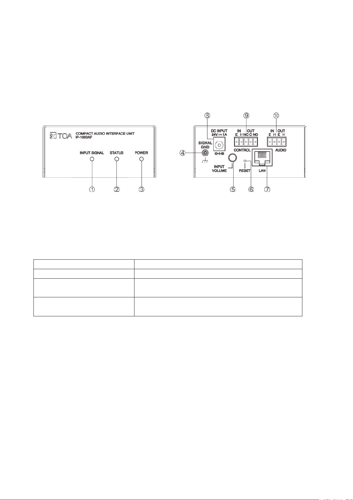
2.2 Interface Description
Front Back
①INPUT SIGNAL: i nput indicator light
②STATUS: status indicator light
③POWER: power indicator light
④Grounding switch
⑤INPUT VOLUM E: inp ut volume adjusting knob, the inp ut volume adjusting, clockwise direction is increase
the volume, counterclockwise is decrease the volume.
⑥RESET: pre ssing the button to restore the factory defau lt IP (or upgrade firmware ) 、br oadcasting IP.
Forced to restore the IP address Electricity stat us, pr essing the button in 3s
Forced into the firmware upgrade
Broadcasting IP
⑦LAN: network interface
⑧Power interface: DC24V/1A
⑨Control input/output interface
IN: control input interface, E is control input r eference place, H is control input interface, when the tw o pins
is short circuit, IP audio interface unit will execute the operat i on automatically, which is setting by browser.
OUT: control output interface, “NC” is cont r ol output normally closed contacts,
“NO” is control output nor ma lly open contacts, “C” i s cont r ol output public contact s.
⑩Audio input/output inter f ac e
IN: audio input interface, E is audio input reference place, H is audio signal input ,1Vrms/10KΩ,unbalance.
OUT: audio output interface, E is audio output reference place, H is audio signal output,1Vrms/600Ω,
unbalance
.
Pressing the button before electricity, and keep it in 5s then
Electricity stat us w it hout network, quickly pressing and
then release it
2-2
Page 7

Chapter 3
Wiring
Page 8
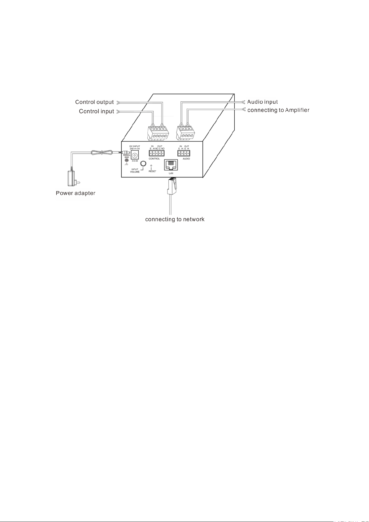
3.1 Wiring diagram
Chapter 3: wiring
3.1 Wiring Diagram
3-1
Page 9

3.2 Installation description
3.2.1Wall-mounted installation diagr a m
It is s only for single device inst allation.
3.2.1.1 Reference size (unit: mm)
Chapter 3: Wiring
3.2 Installation description
3.2.1.2 Please refer to th e f ol l owing picture for installation:
Using the countersun k head screw M 3*6 to fast en the tw o wall-mounted bracket in the two s ides of the device,
and then installing the device in a suitable position by screw(non standard) or expansion screw(non
standard).
3-2
Page 10

Chapter 3: Wiring
3.2 Installation description
3.2.2 Device cabinet installation diagram (2 sets of IP-1000AF installati on)
It is suitable for 2 devices installation, and it need de vice cabinet installation bracket suite for optional
configuration.
3.2.2.1 Reference size (u ni t : mm)
3.2.2.2 Please refer to the f ol lowing picture for inst allation:
Using the half cabinet mounting bracket(MB-IP10B-BK) to fix the two dev ices as the mentioned method, then
using length M5*12 and a bove screw to install the devices i n t he suitable place.
Note: the screw M5 and nut M5 is not incl uded in the fittings
;
3-3
Page 11

Chapter 3:Wiring
3.2 Installation description
3.2.3 Device box installation diagram (4 sets IP-1000AF installation)
It is suitable for 4 devices installation, and it needs installation bracket su ite fo r opt ional configuration.
3.2.3.1Reference size (unit: mm)
3.2.3.2 Please refer to the f ol lowing picture for inst allation:
Using the half cabinet mount ing br acket (MB-IP10B-BK) to fix the four devices as the mentioned metho d, then
using length M5*12 and a bove screw to install the devices i n t he suitable place.
Note: the screw M5 and nut M5 is not incl uded in the fittings
;
3-4
Page 12

3.3 Reference size (unit: mm)
Chapter 3: Wiring
3.3 Reference size
Note: the attached floor mat (10*3) can be pasted on the bottom of the device it is for increasi
ng the device antiskid effect on the desk.
3-5
Page 13

Chapter 4
System setting by browser
Page 14

Chapter 4: System setting by browser
4.1 Entering into browser
4.1 Entering into browser
Step 1: Please input IP address of the IP audio interface unit (factory defaults is 192.168.1.101), then press
Enter.
Step 2: Please input the user name and password in the login window of the Web page (the defaults is
admin).
Note: there is different letter of the use name and password.
Step 3: I t can enter into the Web pa ge after pressed the Enter.
4-1
Page 15

4.2 Network parameters
Identify the unique number of the speaker and it can’t be repeated with
situation.
The defaults sever numb er is 2048, please don’t modify it if not in special ly
is support for switchover of English and Chinese, but the Web page of
bottom segment procedure (BIOS) isn’t support for switchover of English
Chapter 4: System setting by browser
4.2 Network parameters
Device number
IP address IP address of IP audio interface unit
Device port
Subnet mask Please setting subnet mask(the defaults to :255.255.255.0)
Defaults gateway The gateway of the interface unit ( t he defaults is :192.168.1.1)
DNS Server 1 The IP of preferred dom ain interpreter in the interface unit’s network.
DNS Server 2 The IP of standby domain interpret er in the unit’s network.
System server I P address of IP broadcast server
System server port
Language
Handshake interval Setting the interval time b etween the unit and the server.
other terminals or host s.
The defaults port number is 2046, please don’t modify it if not in specially
situation.
The Web page of the spe aker’s application segment procedure (Firmwar e)
and Chinese.
4-2
Page 16

4.3 Audio p arameters
Broadcast coding, PCM means no data be compressed, ADPCM means
Broadcast output
volume
Chapter 4: System setting by browser
4.3 Audio parameters
Coding mode
Line input volume The volume o f aud io line input(0~15).
Broadcasting
sampling rate
packed data (low net work data value).
IP audio interface unit sampling rate in broadcasting.
IP audio interface unit output volume in broadcastin g (0~15).
4-3
Page 17

4.4 Fire alarm parameters
When control input in the status which isn’t trigger the control input
interface,, the status decide the alarm way.(open circuit alarm or closed
alarm output
When the alarm input is triggered, configure whether linkage alarm output
or not.
Chapter 4: System setting by browser
4.4 Firm alarm parameters
Status
Alarm input linkage
Alarm output linkage
recovery time
circuit alarm)
NO: control input interface is closed to trigger the alarm.
OFF: control input interface is disconnected to trigger t he alarm.
The time of alarm output tr iggering
Note: the effective time range is 1-29 S, when setting as 0,that means the
alarm output continue linkage.
4-4
Page 18

Chapter 4: System setting by browser
4.5 WEB management
4.5 WEB management
You can modify the account number and passw or d of the login Web page in the Web management
parameters.
4-5
Page 19

Chapter 4: System setting by browser
4.6 Restarting device
User can click “restart device” to restart the device.
4.6 Restarting device
4-6
Page 20

Chapter 4: System setting by browser
4.7 Resetting to defaults
Resetting defaults: all the parameters will reset to defaults.
4.7 Resetting to defaults
4-7
Page 21

Chapter 4: System setting by browser
4.8 Firmware upgrade
4.8 Firmware upgrade
Clicking into the firmware upgr ade mode to enter the firmware upgrade interface.
Click browse in the upgra de f irmware interface, please select t he cor r ect upgrade files, click on "upgrade", it
will automatically restart after completed the upgrade.
4-8
Page 22

Chapter 4: System setting by browser
4.9 System log
4.9 System log
It can be browsed of the unit log in the Web page, click “delete all logs” can delete all the logs in the Web
page.
4-9
Page 23

Chapter 5
Appendix
Page 24

5.1.1 IP Audio Interface Unit IP-1000AF
Model
IP-1000AF
Power
DC24V
Power consumption
Less than 85mA
Audio input
Range: 1Vrms (Max:2Vrms), unbalanced, impedance 10KΩ
Audio output
Range: 1Vrms, unbalanced, impedance 600Ω
Line input (sampling rates:22K):20~10kHZ
Line output(mp3/samp ling rates:44K):40~15kHZ
Open circuit voltage is DC24V, maximum short-circ uit electric
current≤5mA
Relay NC contact
Control voltage ≤DC30V,control electric current≤500mA
Relay COM contact
Control voltage ≤DC30V,control electric current≤500mA
Relay NO contact
Control voltage ≤DC30V,control electric current≤500mA
Network I/F
10BASE-T/100BASE-TX,automatically determination
Network protocol
TCP,UDP,ARP,ICMP,IGMP
Working temperature
0℃~+40℃
Working humidity
Lower than 90%RH(No dew point)
5P wiring terminal(1PC),4P wiring terminal(1PC),floor
mat(10*3)(4PCS)
Half device cabinet mount ing bracket:MB-IP10B-BK(used for 2
J(used for 4 sets of
IP-1000AF device cabinet installation)
Frequency response
Control input interface
Chapter 5: Appendix
5.1 Specification
Accessories
Optional accessories
sets of IP-1000AF devic e cabinet installation)
Device cabinet bracket installation:MB-IP10B-
5-1
Page 25

TOA Corporation 201611
 Loading...