

Page 1
Instruction Manual
SUSPENSION KIT
HY-700
General Description
The HY-700 speaker suspension kit is designed f o r use with TOA SB-46S and SB-38W low frequency, vented (bass-reflex)
enclosures. The kit features suspension angle indicators and eyebolt mounts to facilitate speaker positioning.
Handling Precautions
Consult a construction expert to ensure mounting bolts
and cables are made of sufficiently strong material to
securely hold the weight of the speakers.
Ensure all mounting eyebolts are securely tightened and
can not be loosened by prolonged exposure to speaker
vibration.
For maximum security, the use of a 6-point suspension
method such as shown in Figure 1 is highly recommended.
TOA takes no responsibility for accidents or injuries caused by
faulty mounting methods or poorly selected mounting locations.
Figure 1
Parts List
1. Suspension bracket No.1
2. Suspension bracket No.2
3. Eyebolt (M16 x 50)
4. Spring lock washer (SW16)
5.
Hex.
nut
4
4
4
4
6. ( + ) woo d screw
7. Spring lock washer (SW4)
8. Flat washer (W4)
(M16)
4
16
16
16
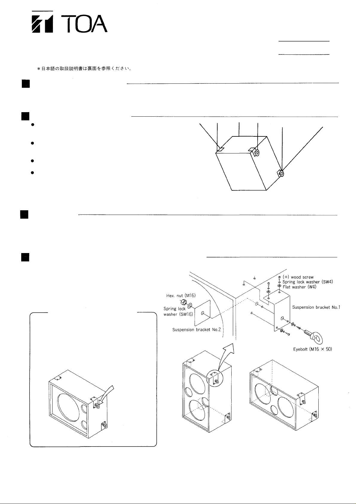
SB-46S/SB-38W Speaker Installation
The speaker enclosures have been pre-fit with suspension bracket mounting holes. Working from inside
the enclosure, use a screwdriver to push out the hole
plugs from the four locations where th e brackets will
be installed. Referring to Figure 2, install the brackets
and eyebolts, ensuring all screws are securely tightened.
N
ote: Horizontal mounting method for the SB-46S
As shown in Figure 3, an anchor nut fo r eyebolt
mounting is already installed inside one corner of
the enclosure, therefore only suspension bracket
No. 1 and the eyebolt need be installed at this
location. Refer again to Figure 2 to install the
brackets for the other three points, ensuring all
screws are securely tightened.
This inside
corner only
Figure 3
Bracket mounting positions for vertical and horizontal
suspension. (4 points each)
Figure 2
Page 2
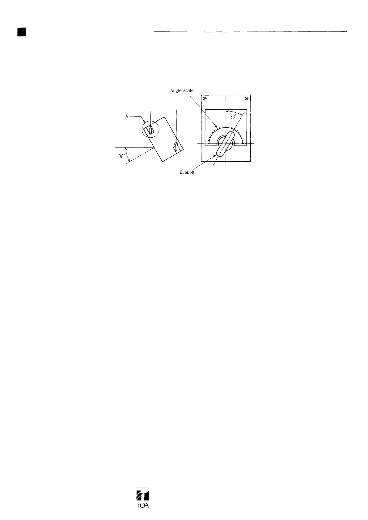
Eyebolt Angle Adjustment
As shown in Figure 4, adjust the suspension angle with the eyebolts referring to the angle scale (in 10° step f or one scale
mark) of the suspension bracket No.1, and tighten all the hexagon nuts securely after adjustment.
The illustration shows that the eyebolt position is ad justed 30° down from horizontal.
Figure 4
TOA Corporation
KOBE, JAPAN
133-05-201-7
A
Page 3

* Please see the reverse side for English manual.
HY-700
Page 4

TOA
 Loading...