

Page 1
INSTALLATION MANUAL
APPLIED INSTALLATION
RACK-MOUNTED EMERGENCY PA SYSTEM
FS-971 SERIES MODEL NUMBERS : FS-971
Page 2

2
TABLE OF CONTENTS
1. SUPPLIED MANUALS ........................................................................................................... 4
2. CONNECTIONS OF INTEGRATED REMOTE CONTROL UNIT RM-971
2.1. Connection Method ................................................................................................................. 5
2.2. Notes on Connections
2.2.1. Maximum line resistance ............................................................................................... 5
2.2.2. Connections of multiple remote control units ................................................................ 6
2.3. Remote Control Unit Numbers/Zone Numbers vs. Fuse Capacity .......................................... 7
2.4. Connections of Multiple Remote Control Units ........................................................................ 8
3. CONNECTION OF REMOTE MICROPHONE RM-1200
3.1. Notes on Connections ............................................................................................................. 9
3.2. Connections .......................................................................................................................... 10
3.3. Connection of the RM-1200's Push-in Terminal Block .......................................................... 11
4. CONNECTION OF REMOTE MICROPHONE RM-1100
(AUX CONTROL TERMINAL)
4.1. Notes on Connections ........................................................................................................... 12
4.2. Connections .......................................................................................................................... 12
4.3. Priority Setting When Multiple RM-1100s Are Connected
4.3.1. Priority setting .............................................................................................................. 13
4.3.2. When not setting the priority order .............................................................................. 13
5. GENERAL BROADCAST AND ATTENUATOR-FREE BROADCAST
DURING POWER FAILURE
5.1. How to Make "Power-Failure" General Broadcast and Attenuator-Free Broadcast .............. 14
5.2. Terminals for Power-Failure General Broadcast and Attenuator-Free Broadcast
5.2.1. Power-failure control input ........................................................................................... 14
5.2.2. Attenuator-free control input ........................................................................................ 14
5.3. Connections .......................................................................................................................... 15
6. CONNECTIONS WHEN MULTIPLE EQUIPMENT RACKS ARE INSTALLED
SIDE BY SIDE
6.1. Expansion Control Panel Connections .................................................................................. 17
6.2. Expansion Junction Panel Connections ................................................................................ 17
6.3. Expansion Junction Panel Connection when Expanding the DC Power Supply Panel ......... 18
6.4. Specifications of Each Cable Set .......................................................................................... 19
Page 3

3
7. ABOUT THE MULTI-ORIGINATION MATRIX SYSTEM ............................................... 20
7.1. How to Divide the Speaker Lines of the Junction Panel ........................................................ 21
7.2. Input Matrix Panel Connections
7.2.1. Possible input and output combinations ...................................................................... 23
7.2.2. Address and audio input/output numbers .................................................................... 24
7.3. IM-011 Address Setting ......................................................................................................... 25
7.4. Front-Mounted Switch Setting and Volume Control Adjustment ........................................... 25
7.5. Connections .......................................................................................................................... 26
7.6. IM-011 Connections
7.6.1. Rear view diagrams and block diagrams .................................................................... 27
7.6.2. Single IM-011 unit: 4-input/4-output configuration ....................................................... 28
7.6.3. Input expansion: 8-input/4-output configuration .......................................................... 28
7.6.4. Output expansion: 4-input/8-output configuration ....................................................... 29
7.6.5. Input/output expansion: 16-input/8-output configuration ............................................. 30
7.6.6. Input/output expansion: 8-input/16-output configuration ............................................. 31
7.6.7. Notes on input level settings when increasing the output ........................................... 32
8. ABOUT THE EP-0510'S STATUS OUTPUTS ............................................................... 34
9. APPENDIX ............................................................................................................................... 35
Page 4
4
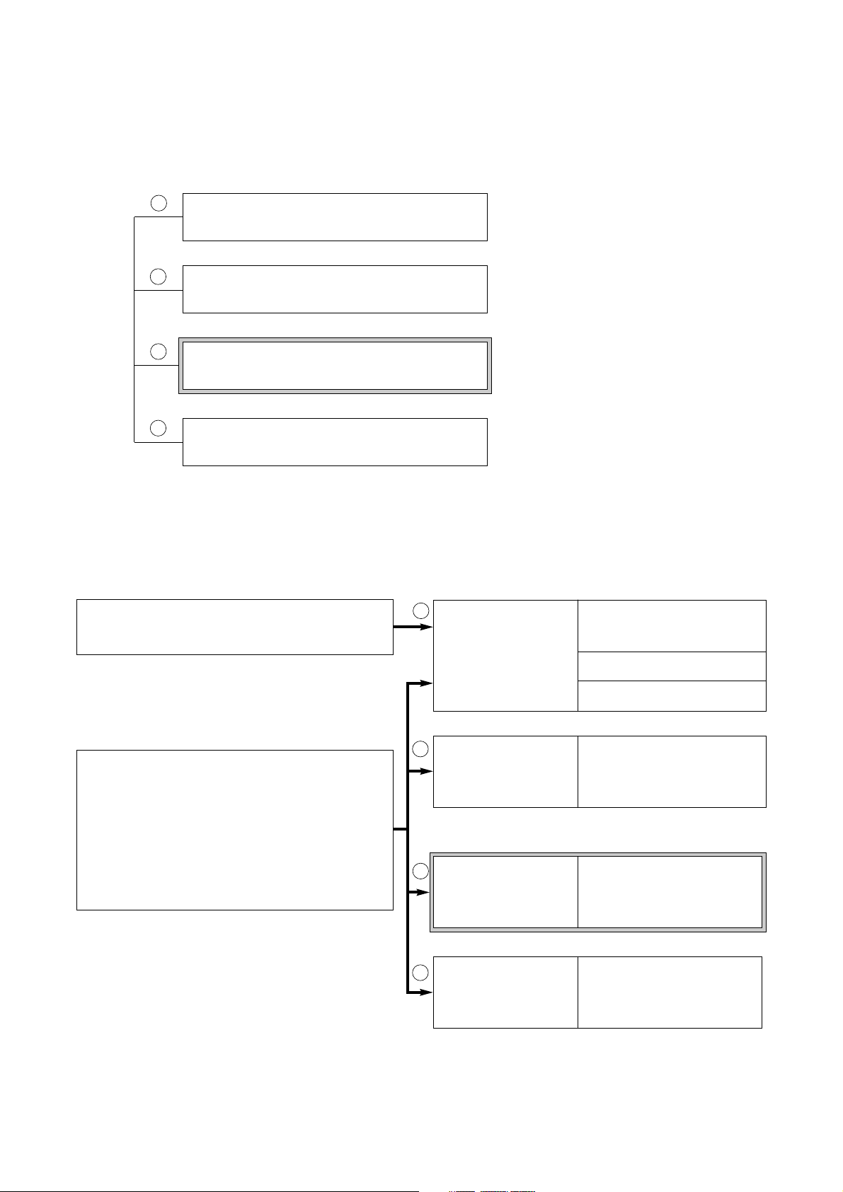
1. SUPPLIED MANUALS
The following manuals are supplied with the emergency PA system.
Read only the manuals that are suited for your purpose.
Installation manual
(Basic installation)
· Installation
· The basics of installation
and its inspection
The book you are reading now
The book you are reading now
Emergency PA System FS-971 Series
Instruction Manual
Emergency PA System FS-971 Series
Installation Manual - Basic Installation
Emergency PA System FS-971 Series
Installation Manual - Applied Installation
Emergency PA System FS-971 Series
Installation Manual - Writing
Installation manual
(Writing)
· Initialization
· Registration setting
· Setting registration chart
· Associated equipment
connections
· Reference items
Installation manual
(Applied installation)
Instruction Manual
· Function
· Operation
· Routine inspection
· Overall inspection
· Those who operate the PA system to make
both emergency and general broadcasts
· Those who install the emergency PA system
· Those who settle on a plan of use, such as
broadcast zone assignment, and write
(register) data
· Those who check system operations
1
2
3
4
1
234
Page 5
Control cable (4 pairs)
Under 50 Ω
Under 50 Ω
Under 50 Ω
Under 50 Ω
Under 50 Ω
Under 50 Ω
5
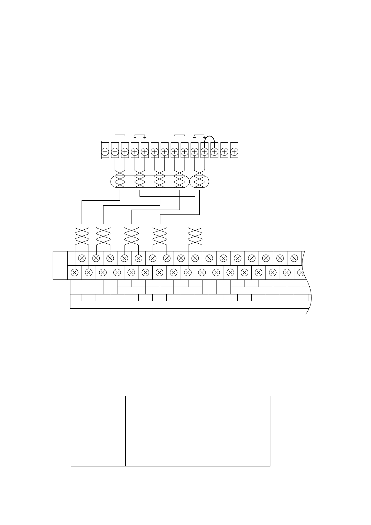
2. CONNECTIONS OF INTEGRATED REMOTE CONTROL UNIT RM-971
2.1. Connection Method
• Use heat-resistant, shielded twisted-paired cables for connection.
• Connect between the front-mounted terminal block of Junction Panel JP-0410 and the terminal block of the
remote control unit.
2.2. Notes on Connections
The maximum cable distance between the main rack and the remote control unit is 800 m, and there is a
limitation to the cable length depending on the type and zone numbers of the connected remote control unit.
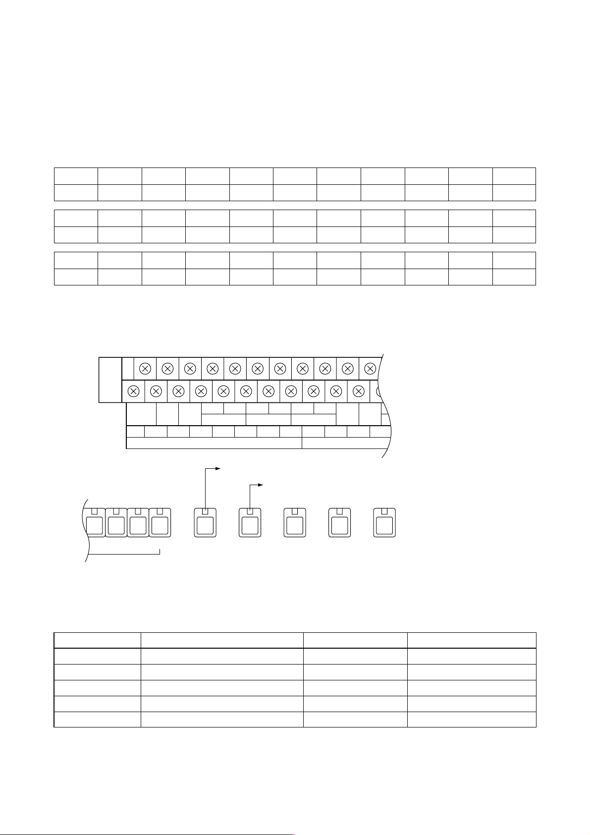
2.2.1. Maximum line resistance
No. of zones
10 zones
20 zones
30 zones
40 zones
50-90 zones
Over 100 zones
Power cable (1 pair)
Under 5 Ω
Under 3 Ω
Under 2.5 Ω
Under 1.5 Ω
Under 1 Ω
Under 0.5 Ω
Remote control unit's terminal block
REMOTE OUT
C HCH
Control line Power supply line
RM BUS
EMG
ACTI
CPU
MONITOR 24 VDC POWER GND
CTRL OFF
C1
EF
(FA)
EMG
ACTI
C2 H2 C3 H3 C4 H4 (
H1
C H GND 24V GND 24V
CPU
OFF
MONITOR
1 EMG RM 24V 2 EMG RM 24V
BATT 1 BATT 2 CHECK
DS CHECK
-
)1 (+)1 (-)2 (+)2 (-)3 (+)3 (-)4 (+)4 GND
EMG REMOTE BUSEMG REMOTE AUDIO IN
GND
JP-0410 front-mounted upper row terminal block
Page 6
6
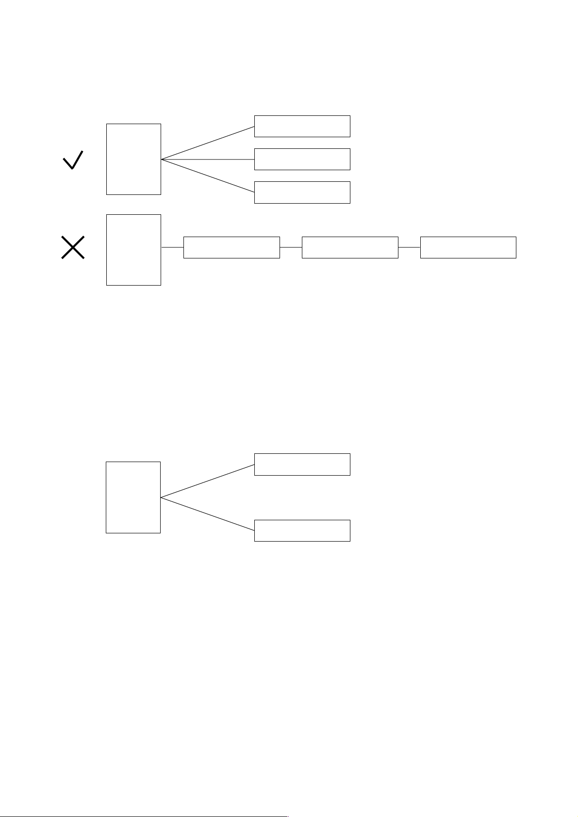
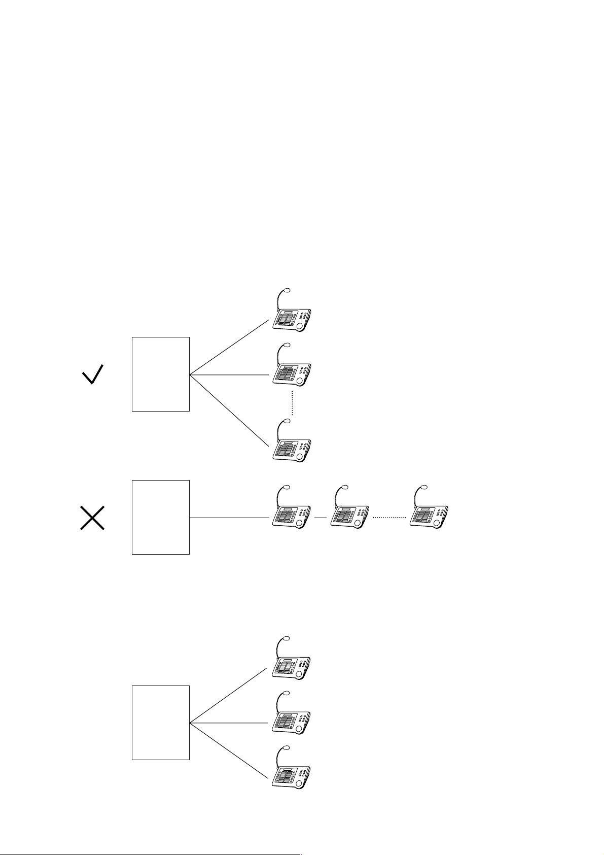
2.2.2. Connections of multiple remote control units
When connecting two or more remote control units, be sure to branch each cable at the main rack.
Remote control unit Remote control unit Remote control unit
Main rack
Main rack
Remote control unit
Remote control unit
Remote control unit
Main rack
Remote control unit
Remote control unit
Total distance of (a) and (b) is shorter than 800 m.
(a)
(b)
Up to eight remote control units can be connected per system. However, when the system includes the
remote control unit of the type that receives power from the main rack, the additional emergency power supply
(p. 24 of Installation Manual - Basic Installation) and the expansion DC power supply (p. 35 of Basic
Installation) may have to be installed in the main rack.
Junction Panel JP-0410 comes with four Emergency RM BUS terminals to control communications with the
remote control unit. Note that up to two remote control units can be connected per terminal, and that the total
distance between the main rack and two remote control units must be shorter than 800 m.
A maximum of two remote control units can be connected per RM BUS terminal.
The JP-0410 is equipped with four Emergency RM Audio Input terminals for audio output from the remote
control unit. Only a maximum of two remote control units can be connected per audio input terminal.
Page 7
Suitable zone numbers
Under 80 zones
90 – 110 zones
120 – 150 zone
160 – 220 zones
230 – 330 zones
7
110 zones
1.2 A
2.3. Remote Control Unit Numbers/Zone Numbers vs. Fuse Capacity
When a large current is consumed depending on the number of connected remote control units and zones,
the JP-0410's fuses (Emergency Remote Control 1 and 2 fuses) for remote control units must be replaced.
The following table shows the relationship between current consumption and zone numbers per remote
control unit.
10 zones
0.3 A
20 zones
0.4 A
30 zones
0.48 A
40 zones
0.58 A
50 zones
0.66 A
60 zones
0.76 A
70 zones
0.84 A
80 zones
0.94 A
90 zones
1.02 A
100 zones
1.12 A
220 zones
2.2 A
120 zones
1.3 A
130 zones
1.38 A
140 zones
1.48 A
150 zones
1.56 A
160 zones
1.66 A
170 zones
1.74 A
180 zones
1.84 A
190 zones
1.92 A
200 zones
2.02 A
210 zones
2.1 A
330 zones
3.18 A
230 zones
2.28 A
240 zones
2.38 A
250 zones
2.46 A
260 zones
2.56 A
270 zones
2.64 A
280 zones
2.74 A
290 zones
2.82 A
300 zones
2.92 A
310 zones
3.0 A
320 zones
3.1 A
EMG RM1
1.6A
EMG RM2 EMG OFF GEN RM CONTROL
1.6A
0.5A 0.5A 3A
10987
For "1 EMG RM 24V"
For "2 EMG RM 24V"
JP-0410 fuse holder
EF
(FA)
EMG
ACTI
CPU
OFF
C H GND 24V GND 24V
BATT 1 BATT 2
MONITOR
1 EMG RM 24V 2 EMG RM 24V
DS CHECK
C1
H1
C2 H2 C3 H3 C4 H4 (
-
)1 (+)1 (-)2 (+)2 (-)3 (+)3
EMG REMOTE BUSEMG REMOTE AUDIO IN
JP-0410 upper row
terminal block
Fuse capacity
2 A
2.5 A
3.15 A
4 A
5 A
Part name
Fuse 250V 2A 5x20 time lag
Fuse 250V 2.5A 5x20 time lag
Fuse 250V 3.15A 5x20 time lag
Fuse 250V 4A 5x20 time lag
Fuse 250V 5A 5x20 time lag
Part code number
115-40-089-00
115-40-090-80
115-40-091-90
115-40-092-20
115-40-093-70
Two circuits of fuse/power supply terminal combinations are provided for the remote control unit. The
maximum permissible current is 5 A for both circuits put together.
When replacing the fuse for the remote control unit, use the "time-lag" type fuse. Note that the fuse exceeding
5 A cannot be used because the fuse holder is 5 A in maximum rating.
Page 8
8
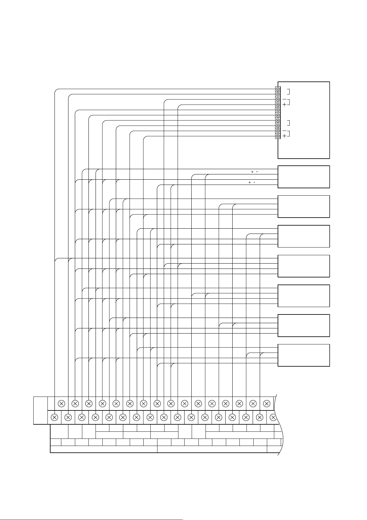
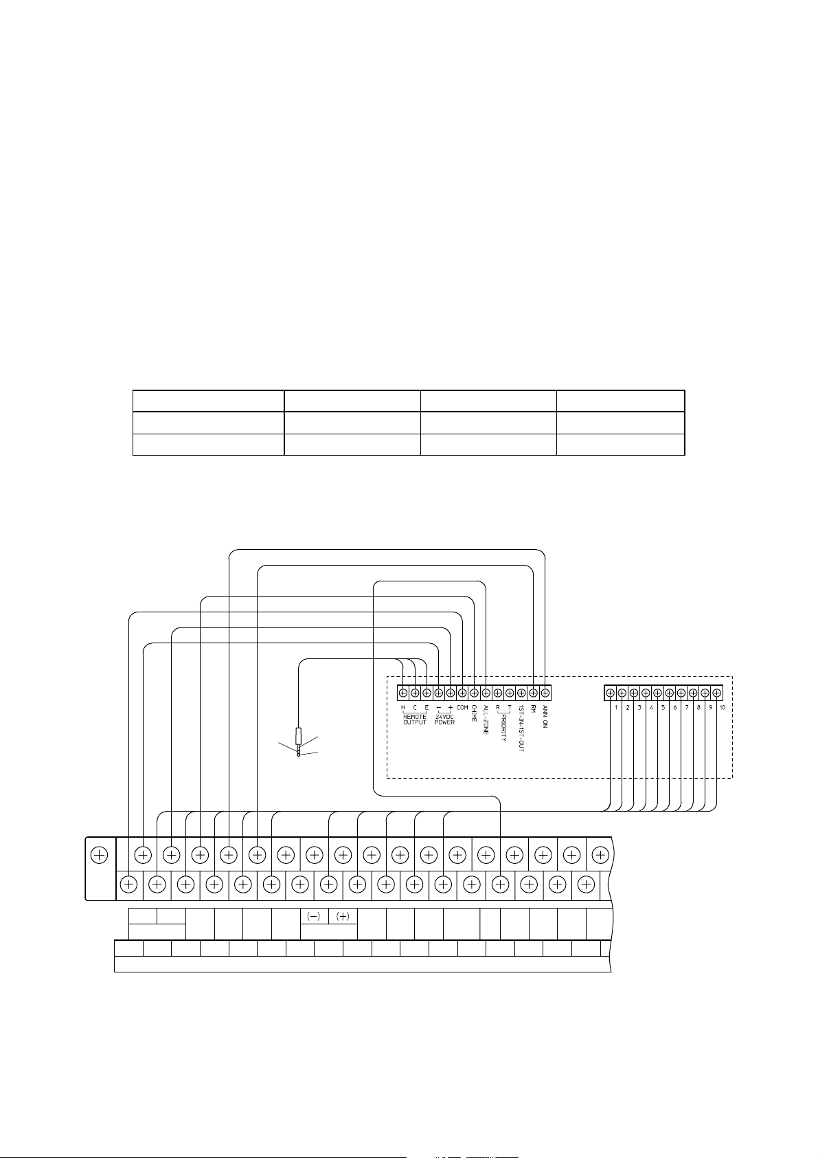
2.4. Connections of Multiple Remote Control Units
• Wiring diagram of Integrated Remote Control Unit
REMOTE OUT (H / C)
RM BUS ( / )
Others
24 VDC ( / )
C
REMOTE OUT
H
RM BUS
EMG ACTI
CPU CTRL OFF
C
MONITOR
H
24 VDC
First remote
control unit
Second remote
control unit
Third remote
control unit
Fourth remote
control unit
Fifth remote
control unit
Sixth remote
control unit
Seventh remote
control unit
Eighth remote
control unit
C1
EF
(FA)
EMG
ACTI
C2 H2 C3 H3 C4 H4 (
H1
C H GND 24V GND 24V
CPU
OFF
MONITOR
1 EMG RM 24V 2 EMG RM 24V
JP-0410 front-mounted upper row terminal block
BATT 1 BATT 2 CHECK
DS CHECK
-
)1 (+)1 (-)2 (+)2 (-)3 (+)3 (-)4 (+)4 GND
EMG REMOTE BUSEMG REMOTE AUDIO IN
GND
Page 9
9
3. CONNECTION OF REMOTE MICROPHONE RM-1200
3.1. Notes on Connections
The maximum distance between the main rack and the RM-1200 is 800 m.
Use cables with line resistance of less than 10 Ω.
Use twisted paired cables for bus lines.
Use two-core shielded cables for signal lines.
When connecting the bus line to the RM-1200, be sure to use the RM-1200's BUS1 terminal.
Be sure to observe the correct polarity when connecting the bus line.
• Connections of multiple RM-1200 units
When connecting two or more RM-1200 units, be sure to branch each cable at the main rack.
Up to 8 RM-1200 units
RM-1200
RM-1200
Distance (a + b + c) must be shorter than 800 m.
(a)
(b)
Main rack
Main rack
Main rack
(c)
A maximum of eight RM-1200 units can be connected. However, the DC power supply is additionally required
when the JP-0410's power capacity is insufficient depending on the system configuration.
Make connections so that the total cable distance between the main rack and the RM-1200 is shorter than 800 m.
Page 10
10
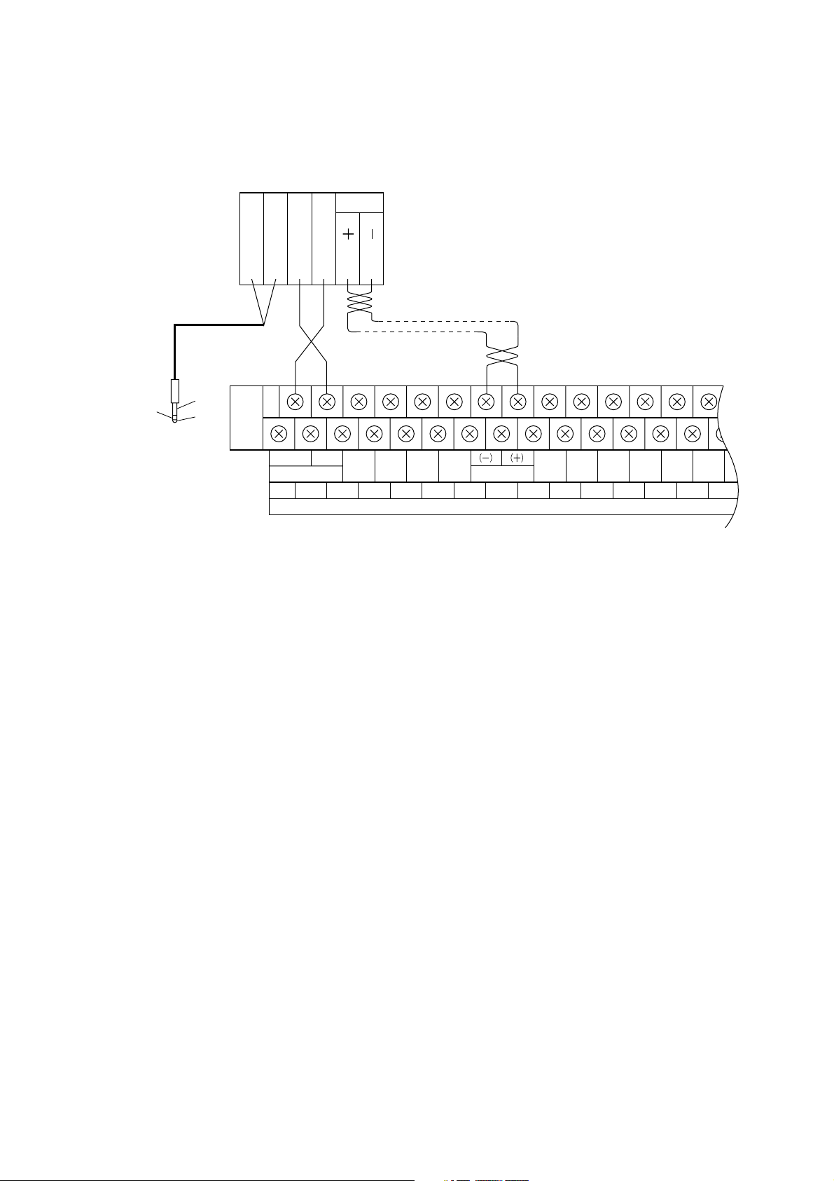
3.2. Connections
RM-1200 terminal block
1
H
Note
Do not connect E of the
phone plug to RM-1200.
Two-core shielded cable Twisted paired cable
C
24V
GND
BUS ( )
BUS ( )
Observe correct polarity
of bus lines.
C
E
H
To pre-amplifier
GND
24 V
CHIME
IN USE
GEM RM PWR
GND
ACTI
112234 5 67 81910
REMOTE
REMOTE
GND
GEN RM BUS
TIMER
GND GND
AUX CONTROL
JP-0410 front-mounted middle row terminal block
PWR FAIL
CTRL
GND
11 12
Page 11
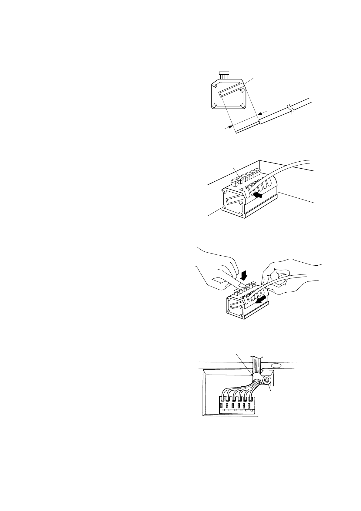
11
1. Strip the cable sheath 9 mm using the strip gauge
provided on the side of the terminal block.
2. Insert the cable into the terminal block.
• Solid cable
Fully Insert the cable into the hole in the terminal
block.
• Twisted cable
Press the lock switch on the terminal block, and
fully insert the cable. Then, release the switch
with the cable inserted.
When removing the cable, pull it out of the terminal
block while pressing the lock switch.
Note: Do not press the lock switch extremely
strong.
3. After connection completion, bundle cables
together using the cable clip, then fix the clip with a
screw.
If cables are too thick to be bundled together,
replace the cable clip with the supplied clip.
3.3. Connection of the RM-1200's Push-in Terminal Block
Strip gauge
9 mm
Lock switch
Cable clip
Note
Do not tighten the clip
extremely strong.
Page 12
Under 1200 m
Over ø1.2 mm
Over ø0.5 mm
12
4. CONNECTION OF REMOTE MICROPHONE RM-1100
(AUX CONTROL TERMINAL)
4.1. Notes on Connections
The maximum cable distance between the main rack and the RM-1100 is 1200 m.
Use two-core shielded cables for signal lines.
Use twisted paired cables for control lines.
Referring to the table below, select the cable to use depending on the cable length.
A maximum of eight (five when the first-in-first-out priority or individual unit priority function is used) RM-1100
units can be connected. However, the DC power supply panel may be additionally required when the JP0410's power capacity is insufficient depending on the system configuration.
• Cable length vs. usable cable
Under 800 m
Over ø0.9 mm
Over ø0.35 mm
Under 400 m
Over ø0.65 mm
Over ø0.26 mm
Cable length
Power/control cable
Shielded cable
4.2. Connections
To connect the remote control unit to the AUX control terminal, operations for "writing" (registration) are
required. For details, refer to the Installation Manual - Writing.
Twin
shielded
cable
C
To pre-amplifier
PP-025B line input
E
H
RM-1100
bottom-mounted terminal block
GND
24 V
CHIME
GEM RM PWR
ACTI
112234 5 67 81910 11121314
IN USE
REMOTE REMOTE
GND
GEN RM BUS
AUX CONTROL
TIMER
GND GND
PWR FAIL
CTRL
GNDGND
JP-0410 front-mounted middle row terminal block
Page 13
13
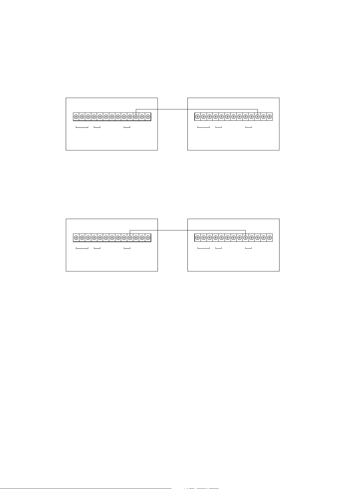
4.3. Priority Setting When Multiple RM-1100s Are Connected
4.3.1. Priority setting
First-in-first-out priority: Connect the First-in-first-out terminal of one remote control unit to the same terminal
of another. Up to five units can be connected for the FIFO priority function.
Remote Control Unit 1 Remote Control Unit 2
ANN ON
RM
1ST-IN-1ST-OUT
RT
PRIORITY
ALL-ZONE
CHIME
COM
+
-
24 VDC
POWER
REMOTE
OUTPUT
H
CE
ANN ON
RM
1ST-IN-1ST-OUT
RT
PRIORITY
ALL-ZONE
CHIME
COM
+
-
24 VDC
POWER
REMOTE
OUTPUT
H
CE
Remote Control Unit 1 Remote Control Unit 2
ANN ON
RM
1ST-IN-1ST-OUT
RT
PRIORITY
ALL-ZONE
CHIME
COM
+
-
24 VDC
POWER
REMOTE
OUTPUT
H
CE
ANN ON
RM
1ST-IN-1ST-OUT
RT
PRIORITY
ALL-ZONE
CHIME
COM
+
-
24 VDC
POWER
REMOTE
OUTPUT
H
CE
Of the two remote control units, the unit making an announcement first takes
precedence. While one unit is in use, other remote control unit cannot be used.
Individual unit priority: Connect the Individual unit priority/sending [priority/T] terminal of the remote control unit
given higher priority to the Individual unit priority/receiving [priority/R] terminal of the unit
with lower priority. Up to five units can be connected.
4.3.2. When not setting the priority order
When using only one RM-1100 unit or when using multiple units but not assigning priority, do not connect the
First-in-first-out terminal or Individual unit priority terminal.
Note
To play chime from the RM-1100, the Pre-amplifier Panel PP-025B which has an internal chime unit CK-025
must be installed in the main rack.
In this example, Remote Control Unit 1 takes precedence over Remote Control Unit 2.
While Unit 1 is making broadcast, Unit 2 cannot be used. Conversely, while Unit 2 is
making broadcast, Unit 1 can be used.
Page 14
14
5. GENERAL BROADCAST AND ATTENUATOR-FREE BROADCAST
DURING POWER FAILURE
5.1. How to Make "Power-Failure" General Broadcast and Attenuator-Free Broadcast
By installing an emergency power supply panel, which is independent of that for emergency broadcast,
general broadcast can be made even during a power failure using the battery. The battery to be installed in
the emergency power supply panel is optional.
Notes
• To make power-failure general broadcast or attenuator-free broadcast, the emergency power supply panel
and battery solely intended for this purpose must be installed in the main rack.
• The emergency power supply panel and battery, installed for emergency broadcast, cannot be used for
power-failure general broadcast or attenuator-free broadcast.
5.2. Terminals for Power-Failure General Broadcast and Attenuator-Free Broadcast
The JP-0410 is equipped with two control inputs, power-failure control input and attenuator-free control input,
for activating general broadcast during a power failure.
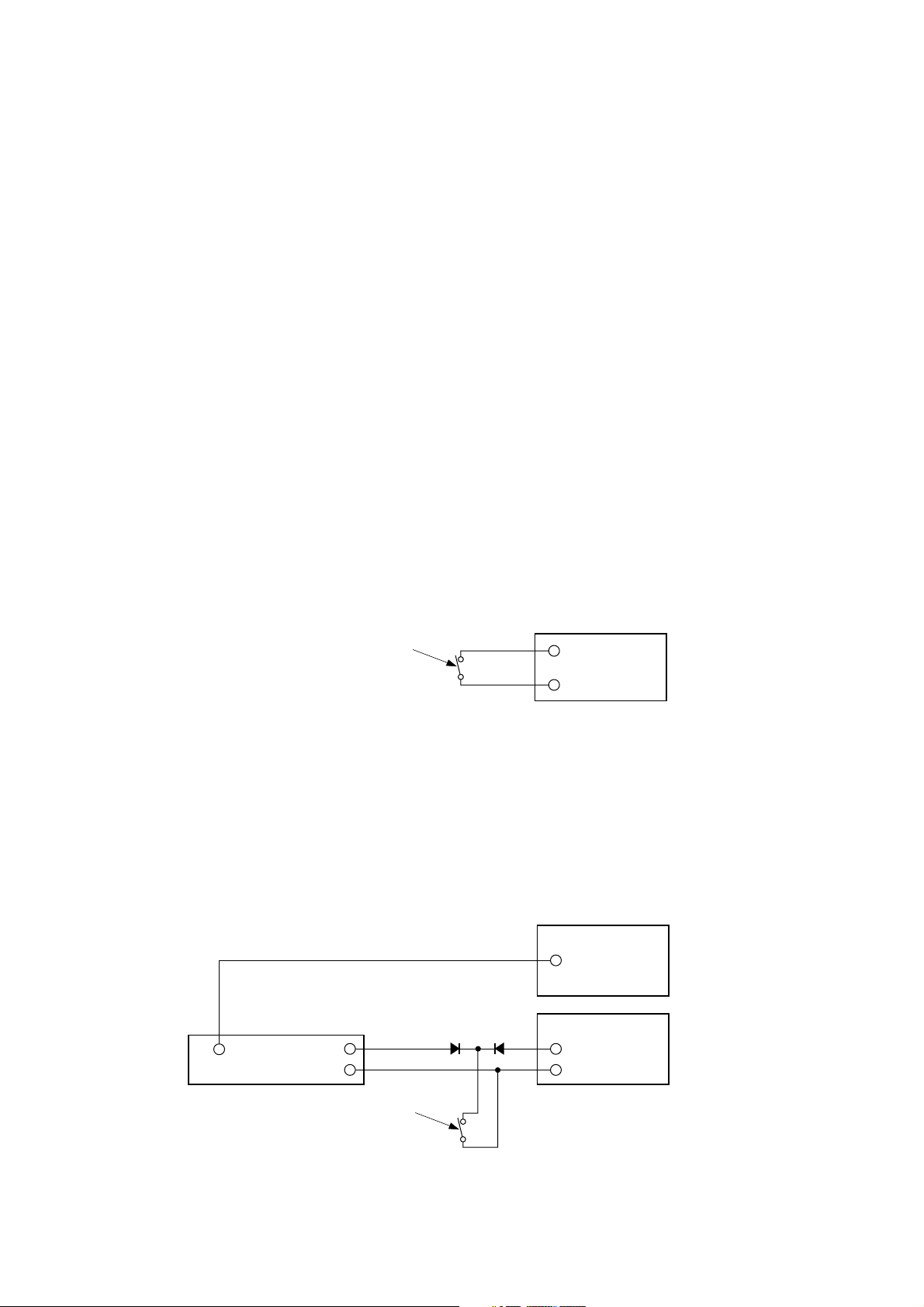
5.2.1. Power-failure control input
Shorting the power failure control input terminal with the grounding terminal supplies power from the
emergency power supply panel for power-failure general/attenuator-free broadcast to equipment, thereby
enabling broadcast. When the power-failure general broadcast gets started, the speaker line is not selected.
To make broadcast, select the speaker line at the main rack or remote control unit.
Ground
Power-failure general broadcast activation contact.
(Procure this switch separately.)
Contact capacity: 30 VDC, over 100 mA
JP-0410 front-mounted
terminal block
Power-failure
control input
Output
JP-0410
EP-0510
Power-failure general broadcast activation contact.
(Procure this switch separately.)
Contact capacity: 30 VDC, over 100 mA
Digital announcer, etc.
(24VDC-operated equipment)
JP-0410 rear-mounted
terminal block
Ground
Attenuator-free
input
Attenuator-free
control input
Start terminal
+
-
Power-failure general broadcast can be made while the switch for activation of power-failure general
broadcast is at make. If the switch for activation of power-failure general broadcast is at break, the powerfailure general broadcast is terminated, putting the system in the standby mode.
5.2.2. Attenuator-free control input
If the attenuator-free control input terminal is shorted with the grounding terminal, attenuator-free broadcast
can be made to the line set by writing even during a power failure. Only the signal connected to the EP-0510's
attenuator-free input is broadcast. In this event, the broadcast is always attenuator-free broadcast (which is
output to R line).
Closing the attenuator-free control input during AC power operation causes the broadcast to take precedence
over other broadcasts.
Page 15

15
5.3. Connections
Notes
• Connections for emergency broadcast are omitted.
• Separately procure both the broadcast switches and diode for reverse current flow prevention.
Power amplifier panel
Digital announcer, etc.
Attenuator-free input
Pre-amplifier
panel
EP-0510
JP-0410
24 VDC
Output
Power-failure general
broadcast switch
Front-mounted terminal
block power failure control
Ground
Diode for prevention
of reverse current flow
Attenuator-free broadcast switch
Emergency power supply panel for power-failure
general broadcast/attenuator-free broadcast
Emergency power supply panel for emergency broadcast
Connection diagram 1
Page 16

16
In Connection diagram 2, attenuator-free broadcast can automatically be made using the digital
announcement machine, etc. when the attenuator-free broadcast switch is shorted. Determine broadcasting
lines by writing into the Integrated Control Panel EP-0510.
Notes
• In this connection example, because power (24 VDC) is always supplied from the battery built in the
emergency power supply panel for power-failure general/attenuator-free broadcasts to the digital announcer,
etc. (even when the attenuator-free broadcast switch is not shorted), the battery is drained quicker than in
the example of Connection diagram 1. Use the battery having a sufficient current capacity.
• The power-failure broadcast function is operated even when the AC power is supplied. In such cases, the
power-failure broadcast takes precedence over all other broadcasts.
When the AC power is supplied, 24 VDC is not output from the emergency power supply panel's control
terminal.
• To automatically inspect the battery for power-failure general/attenuator-free broadcasts, connect the battery
check terminal and VOLT DOWN terminal in the same manner as the emergency power supply panel.
This applies to both connection examples of Connection diagrams 1 and 2.
Attenuator-free
broadcast switch
Attenuator-free input
24 VDC
(+)
(
-
)
Busy output
Output
Digital announcer, etc.
JP-0410
To EP-0510 attenuator-free
broadcast input
Emergency power supply panel for power-failure
general broadcast/attenuator-free broadcast
Connection diagram 2
To power amplifier 24 VDC
Page 17

17
6. CONNECTIONS WHEN MULTIPLE EQUIPMENT RACKS ARE
INSTALLED SIDE BY SIDE
6.1. Expansion Control Panel Connections
When many expansion control panels are used and they are separately installed in different racks, connect
those panels using the optional YR-932 Cable Set.
EP-029-20
EP-029-20
EP-0510
EP-029-20
YR-932 multiple-rack EP-EP power cable
Equipment rack 1 Equipment rack 2
Note : This connection method applies to the EP-029-10
Expansion Control Panel as well.
YR-932 multiple-rack EP-EP control cable
POWER
POWER
POWER
POWER
POWER
CTRL
CTRL
CTRL
CTRL
CTRL
POWER
POWER
CTRL
CTRL
Equipment rack 1
Note : This connection method applies to the JP-039-10
Expansion Junction Panel as well.
JP-039-20
POWER
POWER CTRL
CTRL
JP-039-20
POWER
POWER CTRL
CTRL
Equipment rack 2
YR-933 multiple-rack JP-JP control cable
YR-933 multiple-rack JP-JP power cable
6.2. Expansion Junction Panel Connections
When many expansion junction panels are used and they are separately installed in different racks, connect
them using the optional YR-933 Cable Set.
Page 18

18
6.3. Expansion Junction Panel Connection when Expanding the DC Power Supply Panel
When many expansion junction panels are used and they are separately installed in different racks, and when
the power from a DC power supply panel is also supplied to different racks, modify the optional "YR-933
Multiple-Rack JP-JP Power Cable" and use the modified cable to connect between the DC power supply and
the junction panel.
(-) Yellow
(+) Orange
24 VDC
YR-933 Multiple-Rack JP-JP Power Cable
Cut off here.
Connect to the JP-039 in Rack 1 Connect to the JP-039 in Rack 2
5 Green
4 Yellow
3 Orange
2 Red
1 Brown
To make connections, cut off the orange and the yellow wires in the YR-933 Multiple-Rack JP-JP Power
Cable at the base of connectors of Rack 1, then reconnect both wires to the DC Power Supply Panel AD-011
or AD-031B.
Equipment rack 1 Equipment rack 2
JP-039-20
POWER
24VDC
OUT
-
POWER
24VDC
IN
+-+
AD-011
AD-031B
JP-039-20
POWER
POWER
Note :
This connection applies to the Expansion
Junction Panel JP-039-10 as well.
Yellow
Orange
YR-933 multiple-rack JP-JP power cable
Connect to the DS-029 output terminals
Page 19

19
6.4. Specifications of Each Cable Set
600
4 Yellow
3 Orange
2 Red
1
4
3
2
1
Model No.
Model Name
YR-931
Cable Set
YR-932
Cable Set
Cable
YR-931
EP-EP Power
Expansion Cable
Quantity
1
Length
(mm)
600
Attached
Connector
VH-VH
600
5 Green
4 Yellow
3
2 Red
1 Brown
5
4
3
2
1
YR-931
JP-JP Power
Expansion Cable
1 600
VH-VH
5000
Black
Red
4
3
2
1
YR-931
EP-AD Power
Expansion Cable
1 5000
VH
5000
3 White
2 Black
1 Red
3
2
1
Gray
5000
5 Green
4 Yellow
3 Orange
2 Red
1 Brown
5
4
3
2
1
YR-932
Multiple-Rack
EP-EP Control
Cable
1 5000
SMR-SMR
5000
Black
Red
5
4
3
2
1
YR-931
JP-AD Power
Expansion Cable
1 5000
VH
5000
4 Yellow
3 Orange
2 Red
1 Brown
4
3
2
1
YR-932
Multiple-Rack
EP-EP Power
Cable
1 5000
VH-VH
YR-933
Cable Set
5000
3 White
2 Black
1 Red
3
2
1
Gray
YR-933
Multiple-Rack
JP-JP Control
Cable
1 5000
SMR-SMR
YR-933
Multiple-Rack
JP-JP Power
Cable
1 5000
VH-VH
Appearance
Refer to p. 36 and p. 37 of the "Installation Manual - Basic Installation" for connections of the YR-931 cable.
Page 20

20
7. ABOUT THE MULTI-ORIGINATION MATRIX SYSTEM
By employing the Input Matrix Panel IM-011, you can provide simultaneous outputs of paging calls or
background music (BGM) separately to different zones.
• One Input Matrix Panel IM-011 provides 4 inputs/4 outputs matrix configuration.
• Programs of up to four sound sources can be simultaneously broadcast per IM-011.
However, the IM-011's Input 1 is designated as an input for emergency broadcast.
• Up to eight IM-011s can be connected, permitting matrix configuration of a maximum of 16 inputs and 8
outputs or 8 inputs and 16 outputs.
• Write the setting into the Integrated Control Panel EP-0510.
(Refer to the Installation Manual - Writing.)
• Address numbers must be set for the IM-011. (Refer to p. 25.)
[System Example]
Security center, etc.
M
Zone A
Zone B
Zone C
Integrated Control
Panel
EP-0510
General-purpose
remote control unit
General-purpose
remote control unit
BGM, etc.
Input 1
Input 2
Input 3
Input 4
Input
Matrix
Panel
IM-011
Output 1
Output 2
Output 3
Output 4
Power Amplifier
Panel
Junction Panel
JP-0410
JP-039-20
JP-039-20
JP-039-10
Zone A
Zone B
Zone C
Page 21

21
7.1. How to Divide the Speaker Lines of the Junction Panel
Junction panel's power amplifier terminals can be divided for a group of consecutive five lines.
For multi-origination broadcast, remove jumper wires on the power amplifier terminals so that the outputs of
the power amplifier panel are divided for each broadcasting zone.
• The 10-zone Expansion Junction Panel JP-039-10 is not equipped with terminals C3, C4, H3, and H4.
• Remove jumper wires from both C and H terminals depending on the combinations.
GND C1 C2
H1 H2
AMP
FAULTFAULT
BATTERYGEN DSEMG DS
CHECKCTRL
+
CTRL +ACTI
+
ACTI
+
CHIME
OUTOUTIN
TIMER
2
EMG
24 V
24 V
ATT
FREE
Jumper wires
POWER AMPLIFIER
C1 C2 C3 C4 H1 H2 H3 H4
JP-039-20 rear-mounted terminal block
JP-0410 rear-mounted terminal block
20-zone Expansion Junction Panel
Junction Panel
Page 22

22
• Be sure to divide the speaker lines when connecting two or more power amplifier panels to the junction
panel or expansion junction panel. Failure to do this shorts the power amplifier panel outputs, causing
damage to the power amplifier panels.
H1, C1
Remove jumper wires.
H2, C2
H3, C3
H4, C4
The figure is based on the JP-039-20.
Neither the JP-039-10 nor the JP-0410 has lines 11-20.
Line 1
Line 5
Line 6
Line 10
Line 11
Line 15
Line 16
Line 20
Page 23

23
7.2. Input Matrix Panel Connections
• Up to eight Input Matrix Panels IM-011 can be connected.
• Inputs and outputs must be of full matrix configuration (i.e. I/O configuration must be as shown below). Also,
the address of each panel must be set correctly depending on the input and output configuration. If not
correctly set, the matrix panel does not operate normally.
7.2.1. Possible input and output combinations
Note
Combinations other than those above are impossible. Connections are impossible for five and seven units.
6 units
8 inputs/12 outputs
12 inputs/8 outputs
8 units
8 inputs/16 outputs
16 inputs/8 outputs
Connected input Nos. Audio I/O Nos.
1 unit 4 inputs/4 outputs
2 units
4 inputs/8 outputs
8 inputs/4 outputs
3 units
4 inputs/12 outputs
12 inputs/4 outputs
4 units
4 inputs/16 outputs
8 inputs/8 outputs
16 inputs/4 outputs
Address of the IM-011 to use
0
0 1
4
0
0 1 2
8
4
0
0 1 2 3
5
041
A
8
4
0
6
04152
8
9
4
5
0
1
0415263
A
B
8
9
4
5
0
1
7
Page 24

24
[Important]
Audio Input 1 is solely intended for emergency broadcast. Be sure to connect Input 1 to the EP-0510's
Emergency/General output.
7.2.2. Address and audio input/output numbers
Audio input
Dedicated input for
emergency broadcast
16
15
14
13
12
11
10
4
Address
3
2
1
4
3
2
1
9
4
8
3
7
2
6
1
5
4
4
3
3
2
2
1
1
A
123
Address
8
123
Address
4
123
Address
0
1234
123
4
Address
3
2
1
4
4
3
2
1
4
4
3
2
1
4
4
3
2
1
4
B
1234
Address
9
1234
Address
5
123
4
Address
1
1234
5678
4
Address
3
2
1
1234
4
Address
3
2
1
1234
9101112
4
Address
6
2
3
2
1
1234
4
Address
3
2
1
1234
13 14 15 16
7
3
Audio output
Page 25

25
7.3. IM-011 Address Setting
1. Remove the IM-011's two front panel screws to remove the front panel.
2. Rotate the address switch with a screwdriver to set the address.
Input level setting switch
Selects either –20 dBV or 0 dBV depending on
the input source signal level. The switch is set to
the [0 dBV] position at the factory.
Input volume control
Adjusts the sound volume.
(The control is set to the MAXIMUM
position at the factory.)
Set the control mode switch
to the [AUTO] position. The
switch is set to the [AUTO]
position at the factory.
When the control mode switch is in the [AUTO]
position, the switching time setting switch and the
input/output setting switch are both disregarded.
Both switches can be used when the control
mode switch is in the [MANUAL] position.
AUTO
MANUAL
CONTROL SW
7.4. Front-Mounted Switch Setting and Volume Control Adjustment
Ensure that the front panel is replaced after setting and adjustment completion.
Note
Emergency broadcast is output at the maximum
volume level regardless of the input volume
control setting.
Remove screws to remove the front panel.
ADDRESS
F
0
1
E
2
D
3
C
4
B
5
6
A
7
9
8
Rotate the address switch with screwdriver to set the address.
The switch is set to 0 at the factory, as shown in the figure.
Page 26

26
7.5. Connections
Power amplifier
panel
Monitor Panel
MP-011
Pre-amplifier Panel
PP-025B
Integrated Control
Panel EP-0510
Expansion Control
Panel EP-029-20
Input Matrix
Panel IM-011
Power amplifier panel
Input sources, such as the general-purpose
remote control unit and BGM player
To DC Power Supply Panel
Junction Panel
JP-0410
Expansion Junction Panel
JP-039-20
Note : Connections of both the emergency broadcasting and power supply sections are omitted.
Page 27

27
7.6. IM-011 Connections
7.6.1. Rear view diagrams and block diagrams
Notes
• Be sure to connect the EP-0510's Emergency/General output to Audio Input 1 of the "Address 0" IM-011
Panel connected to the power amplifier panel. Wrong connections disable the emergency broadcast
function.
• Only the Audio Input 1 signal of the "Address 0" IM-011 Panel is output when in emergency broadcast mode.
EP-0510's rear panel
Control cable attached
to IM-011
IM-011's rear panel
24 VDC input
(Connect this input to the DC Power Supply Panel's 24 VDC OUT terminal.)
Connect Audio Input 1 of the "Address 0" Input Matrix Panel IM-011 to the
Emergency/General output of the Integrated Control Panel EP-0510.
Block diagram
Expansion
Expansion
audio input
1234
1234
Expansion
audio output
External control input
(Used for manual control. Not used in combinations with the FS-970 series.)
Audio
input
1234
Audio
input
1234
Audio
output
audio input
1234
4
3
2
1
1234
Audio
output
4
3
2
1
Expansion
audio output
Page 28

28
7.6.2. Single IM-011 unit: 4-input/4-output configuration
7.6.3. Input expansion: 8-input/4-output configuration
To Integrated Control Panel EP-0510
Address 0
Emergency/General output
1
1234
To power amplifier panel input
IM-011 control
4
3
2
To input source
(general-purpose remote control unit, BGM player, etc.)
Audio input
number
4
3
2
1
1234
4
3
2
1
1234
1234
4
3
2
1
Audio output
number
EP-0510 Emergency/General output
[ ] stands for the address number.
Address 4
To Integrated Control Panel EP-0510
Address 0
Emergency/
General output
1
1234
To power amplifier panel input
IM-011
control
8
7
To input source
6
5
Audio input
number
4
3
To input source
2
1234
4
8
3
7
2
6
1
5
1234
4
3
2
1
Audio
output
Expansion
1234
4
4
3
3
2
2
1
1
1234
1234
audio input
4
3
2
1
Audio output
number
EP-0510 Emergency/General output
[ ] stands for the address number.
Page 29

29
7.6.4. Output expansion: 4-input/8-output configuration
Address 1
56 78
To Integrated Control Panel EP-0510
Address 0
Emergency/General output
1
234
1
IM-011 control
To power amplifier panel input
4
To input source
3
2
Audio input
number
4
3
2
1
To power amplifier panel input
Expansion
audio output
1234
4
3
2
1
1234
1234 5678
4
3
2
1
Audio
input
1234
4
3
2
1
1234
[ ] stands for the address number.
4
3
2
1
Audio output
number
Page 30

30
7.6.5. Input/output expansion: 16-input/8-output configuration
[ ] stands for the address number.
Audio input
Input
13 14 15
16
number
16
15
14
13
1234
4
3
2
1
1234
1234
4
3
2
1
4
3
2
1
1234
4
3
2
1
Input
91011
12
Input
5678
Input
123
1234
4
To power amplifier
panel input
567
8
To power amplifier
panel input
12
11
10
9
8
7
6
5
4
3
2
1
1234
4
3
2
1
1234
1234
4
3
2
1
1234
1234
4
3
2
1
1234
1234 5678
4
3
2
1
4
3
2
1
4
3
2
1
1234
4
3
2
1
1234
1234
4
3
2
1
1234
1234
4
3
2
1
1234
Audio output number
4
3
2
1
4
3
2
1
4
3
2
1
To [Emergency/General] output
of Integrated Control Panel EP-0510
Page 31

31
7.6.6. Input/output expansion: 8-input/16-output configuration
[ ] stands for the address number.
Input
Input
8
4
1
567
8
567
123
1234
9101112 13 14 15 16
To power amplifier
panel input
To [Emergency/General] output
of Integrated Control Panel EP-0510
Audio input
number
1234
4
8
3
7
2
6
1
5
1234
1234
4
4
3
3
2
2
1
1
1234
123
4
3
2
1
4
3
2
1
4
To power amplifier
panel input
1234
4
3
2
1
1234
1234
4
3
2
1
1234
5678
4
3
2
1
4
3
2
1
Audio output number
To power amplifier
panel input
1234
4
3
2
1
1234
1234
4
3
2
1
1234
9 101112
4
3
2
1
4
3
2
1
To power amplifier
panel input
1234
4
3
2
1
1234
1234
4
3
2
1
1234
13141516
4
3
2
1
4
3
2
1
Page 32

32
7.6.7. Notes on input level settings when increasing the output
When increasing output numbers to 8, 12 or 16 outputs by connecting two or more IM-011s, the inputs
common to each IM-011 unit must be set for the same level. Refer to the following examples.
• Eight outputs
Important: All of the above input levels must have the same setting regardless of increased input numbers.
The figure below shows the inputs of both "Address 0" and "Address 1" panels are set for the same level
when their outputs are increased.
Set all inputs 1–4 of both the "address A" and "address B" panels
for the same level.
Set all inputs 1–4 of both the "address 0" and "address 1" panels
for the same level.
Set all inputs 1–4 of both the "address 8" and "address 9" panels
for the same level.
Set all inputs 1–4 of both the "address 4" and "address 5" panels
for the same level.
Audio input/output expansion (16 inputs/8 outputs configuration)
Note: "Exp" in the figure is short for "expansion".
1234
Exp audio input
4
3
Address
2
1
A
Audio input
Audio output
1234
4
3
2
Exp audio output
1
1234
Exp audio input
4
3
Address
2
1
B
Audio input
Audio output
4
3
2
Exp audio output
1
1234
Exp audio input
4
3
Address
2
1
4
3
2
1
4
3
2
1
8
Audio input
Audio output
1234
Exp audio input
Address
4
Audio input
Audio output
1234
Exp audio input
Address
0
Audio input
Audio output
4
3
2
Exp audio output
1
4
3
2
Exp audio output
1
4
3
2
Exp audio output
1
1234
Exp audio input
4
3
Address
2
1
4
3
2
1
4
3
2
1
9
Audio input
Audio output
1234
Exp audio input
Address
5
Audio input
Audio output
1234
Exp audio input
Address
1
Audio input
Audio output
4
3
2
Exp audio output
1
4
3
2
Exp audio output
1
4
3
2
Exp audio output
1
Audio input 2
Expansion audio output 2
Audio input 2
Expansion audio output 2
0 dB
-
20 dB
Input level setting switch
0 dB
-
20 dB
Input level setting switch
To internal circuit
Address 0
To internal circuit
Address 1
Page 33

33
The following figure shows the inputs of both "Address 0" and "Address 1" panels are set for different levels
when their outputs are increased.
Set Inputs 1–4 of the "address 4–6" panels for
the same level.
Set Inputs 1–4 of the "address 0–2" panels for
the same level.
Set Inputs 1–4 of the
"address 4–7" panels for
the same level.
Set Inputs 1–4 of the
"address 0–3" panels for
the same level.
If, as shown in the figure above, the input level of the "Address 0" panel has a different setting from that of the
"Address 1" panel when their audio outputs are increased,
(1) Setting the "address 1" panel for an adequate volume level will result in a significantly larger input to the
"address 0" panel.
(2) Setting the "address 0" panel for an adequate volume level will result in a significantly smaller input to the
"address 1" panel.
• Twelve outputs
• Sixteen outputs
Audio input 2
Expansion audio output 2
Audio input 2
Expansion audio output 2
0 dB
-
20 dB
Input level setting switch
0 dB
-
20 dB
Input level setting switch
To internal circuit
Address 0
To internal circuit
Address 1
Audio input/output expansion (8 inputs/12 outputs configuration) Note: "Exp" in the figure is short for "expansion".
1234
Exp audio input
4
3
Address
2
1
4
Audio input
Audio output
1234
1234
Exp audio input
4
4
3
3
2
2
Exp audio output
1
1
Audio input
Audio output
Address
5
4
3
2
Exp audio output
1
1234
Exp audio input
4
3
Address
2
1
6
Audio input
Audio output
4
3
2
Exp audio output
1
1234
Exp audio input
4
3
Address
2
1
0
Audio input
Audio output
4
3
2
Exp audio output
1
1234
Exp audio input
4
3
Address
2
1
1
Audio input
Audio output
1234
Exp audio input
4
4
3
3
2
2
Exp audio output
1
Audio input
1
Address
2
Audio output
4
3
2
Exp audio output
1
Audio input/output expansion (8 inputs/16 outputs configuration) Note: "Exp" in the figure is short for "expansion".
1234
Exp audio input
4
3
Address
2
1
4
Audio input
Audio output
1234
1234
Exp audio input
4
3
Address
2
1
0
Audio input
Audio output
1234
Exp audio input
4
4
3
3
2
2
Exp audio output
1
4
3
2
Exp audio output
1
Audio input
1
Audio output
1234
Exp audio input
4
3
2
Audio input
1
Audio output
Address
5
Address
1
4
3
2
Exp audio output
1
4
3
2
Exp audio output
1
1234
Exp audio input
4
3
Address
2
1
4
3
2
1
6
Audio input
Audio output
1234
Exp audio input
Address
2
Audio input
Audio output
1234
Exp audio input
4
4
3
3
2
2
Exp audio output
1
4
3
2
Exp audio output
1
Audio input
1
1234
Exp audio input
4
3
2
Audio input
1
Address
7
Audio output
Address
3
Audio output
4
3
2
Exp audio output
1
4
3
2
Exp audio output
1
Page 34

Status to Turn Output On
Warning Announcement or other audio alarm other than the second
signal is being output.
Warning Announcement indicator is on or flashing during or before
and after Warning Announcement.
Evacuation Announcement indicator is on or flashing during or before
and after Evacuation Announcement.
False Alarm Announcement indicator is on or flashing during or
before and after False Alarm Announcement.
Emergency announcement is being made from the PA microphone.
Communication error with the emergency remote control unit or other
irregularity has occurred and the failure indication is being displayed.
General broadcast is being made from any connected equipment.
Equipment do not correctly operate because of writing or overall
check.
34
8. ABOUT THE EP-0510'S STATUS OUTPUTS
These outputs show the status of the Integrated Control Panel EP-0510, and each output turns on when in the
following states.
Signals from these outputs are provided from the status output connector (10-pole SM connector) located on
the EP-0510's rear panel. Pins of the connector are arranged as follows.
Output Name
Audio Alarm Output On
Warning Announcement On
Evacuation Announcement On
False Alarm Announcement On
Microphone Announcement On
Abnormality In Progress
General Broadcast On
System Check In Progress
Pin No. Signal Name Rating
1 Ground
–
2 Audio Alarm Output On Withstand voltage: 24 VDC, Current capacity: 0.1 A
3 Warning Announcement On Withstand voltage: 24 VDC, Current capacity: 0.1 A
4 Evacuation Announcement On Withstand voltage: 24 VDC, Current capacity: 0.1 A
5 False Alarm Announcement On Withstand voltage: 24 VDC, Current capacity: 0.1 A
6 Microphone Announcement On Withstand voltage: 24 VDC, Current capacity: 0.1 A
7 Abnormality In Progress Withstand voltage: 24 VDC, Current capacity: 0.1 A
8 General Broadcast On Withstand voltage: 24 VDC, Current capacity: 0.1 A
9 System Check In Progress Withstand voltage: 24 VDC, Current capacity: 0.1 A
10 +5 V Current capacity: 1 mA
EP-0510
12345678910
Pin No.
Status output connector
(10-pole SM connector)
Page 35

35
9. APPENDIX
This appendix focuses on hints on installation and connections of associated equipment to the FS-971 Series.
TABLE OF CONTENTS
9.1. Notes on Parallel Rack Installation
9.1.1. Securing racks installed side by side ................................................................ 36
9.1.2. Adjusting the rack height ................................................................................... 36
9.2. Specifications and Connections of Monitor Panel MP-011
9.2.1. Specifications .................................................................................................... 37
9.2.2. Connections ...................................................................................................... 38
9.3. Connections to the PBX and Intercom Systems .................................................... 39
9.4. Source Equipment Connections .............................................................................. 40
9.5. Tables for Each Panel's Switch Settings
9.5.1. Integrated Control Panel EP-0510 .................................................................... 41
9.5.2. Expansion Control Panels EP-029-10 and EP-029-20 ..................................... 42
9.5.3. Junction Panel JP-0410 .................................................................................... 42
9.5.4. Expansion Junction Panels JP-039-10 and JP-039-20 ..................................... 42
9.5.5. Input Matrix Panel IM-011 ................................................................................. 42
9.5.6. Integrated Remote Control Panel EP-059R ...................................................... 43
Page 36

36
9.1. Notes on Parallel Rack Installation
9.1.1. Securing racks installed side by side
Two knock-out holes (ø12 mm) are provided on each side of the rack. Break these holes using a screwdriver,
and secure racks to each other with M8 bolts and nuts.
9.1.2. Adjusting the rack height
(A standard screwdriver is required to adjust the height.) When multiple racks installed on the floor are
unstable, adjust their height and secure levelness by turning clockwise the height adjustment screw located at
the rack base front.
Page 37

24 VDC
400 mA (rated output)
10 inputs - Amplifier output level: 50 V, 70 V, 100 V (changeable)
Line output level: 0 dBV (1 V)
33 x 140 mm dynamic speaker, 3 W / 8 Ω
7-segment LED meter
Emergency control signal (bypassing attenuators)
Talk switch signal (prevention of feedback)
Black, 30% gloss
482 (w) x 44 (h) x 219.1 (d) mm
2.5 kg
4-pole connector cable ................. 1
Rack mounting screw ................... 4
Name label ................................... 1
37
9.2. Specifications and Connections of Monitor Panel MP-011
9.2.1. Specifications
A maximum of ten amplifier inputs and outputs can be switched and each of their levels monitored by means
of the monitor speaker and level meter.
Power Source
Current Consumption
Input
Monitor Speaker
Meter
Control Signal Input
Finish
Dimensions
Weight
Accessories
• Appearance
[Rear view]
[Front view]
420
465
482
4 - 6 x 10
31.8
44
Page 38

38
9.2.2. Connections
• Connecting the Monitor Panel to the Integrated Control Panel EP-0510 permits emergency broadcast to be
monitored at the specific volume level regardless of the volume control setting. When the PA microphone
attached to the EP-0510 is used, the monitoring level automatically lowers to prevent feedback.
• For ten input circuits, by changing the jumper connector position, individual power amplifier or line output
levels can be selected. (All inputs are set for the power amplifier output level at the factory.)
• All of the ten input circuits can be simultaneously switched to the power amplifier output levels of 50 V, 70 V
or 100 V.
MP-011 top view (case removed)
Jumper connector
12345 678910
100 V, 70 V, 50 V position
(Factory-preset position)
1 V (line level) position
Yellow
Orange
Red
Brown
Printed circuit board
MP-011 rear view
To each power amplifier
output or line output
MP-0510 rear panel
These cables are supplied
MP-011 power supply
with MP-011.
Page 39

39
9.3. Connections to the PBX and Intercom Systems
By connecting the PA system to the PBX and intercom system, paging calls can be made from the telephone
or intercom station. Short the power control starting cable between the AUX control and grounding terminals.
The power amplifier's power is switched on and the speaker lines set in the writing are selected.
( Exchange )
Audio signal
To pre-amplifier
Power control starting cable
GND
24 V
GEM RM PWR
1
2
CHIME
ACTI
34 5 67 81910
IN USE
REMOTE REMOTE
1
2
GND
GEN RM BUS
JP-0410 front-mounted middle row terminal block
TIMER
GND GND
AUX CONTROL
PWR FAIL
CTRL
GNDGND
Page 40

40
9.4. Source Equipment Connections
When using a timer to activate source equipment to play a time signal chime or broadcast commercial
messages, connect the equipment's "Play on" output to the Timer or AUX control terminal of the JP-0410's
front-mounted terminal block.
Equipment name Model No. Input terminal Play on output terminal name
Digital Announcer EV-350P/-350R Start 1, 2 Busy
[Connection to the Timer terminal]
[Connection to the AUX terminal]
* The "Play on" terminal refers to the terminal that is at make while the equipment is playing. The following
table shows the relationship of the input to "Play on" terminals of the source equipment to be connected.
Timer
Control output
GND
GEM RM PWR
24 V
1
JP-0410 front-mounted middle row terminal block
Timer
Control output
Input*
CHIME
ACTI
2
Input*
Source equipment
REMOTE REMOTE
IN USE
34 5 67 81910
1
2
GND
Source equipment
Play on output*
GEN RM BUS
AUX CONTROL
Play on output*
TIMER
GND GND
To pre-amplifier
PWR FAIL
CTRL
GNDGND
To pre-amplifier
GND
24 V
GEM RM PWR
1
2
CHIME
ACTI
34 5 67 81910
IN USE
REMOTE REMOTE
1
GEN RM BUS
2
GND
TIMER
GND GND
AUX CONTROL
PWR FAIL
CTRL
GNDGND
JP-0410 front-mounted middle row terminal block
Page 41

41
9.5. Tables for Each Panel's Switch Settings
Note: Each figure of switch shows the factory-preset position.
9.5.1. Integrated Control Panel EP-0510
ON
ON
67
ON
OFF
1
Combination of 1 and 2
Equipment that can
play main rack BGM
2 3 4 5 6 7 8
Be sure to set the switch to the OFF (Normal) position after checking line operation status.
12345
OFF
SW1 setting function
For inspection (Be sure to set these switches to OFF.)
SW1
8
Line
Normal
Zone lamp
indication
Main rack system and all integrated remote
1
1 2
control units (Factory-preset position)
2
Main rack only
ON
OFF
SW2, SW3 (Same construction)
1
ON
OFF
Possible Check On +8 minutes +4 minutes +2 minutes +1 minute
Impossible Normal Off
Emergency reset by
pressing key twice
Normal/
check
1
ON
OFF
Resumed
Terminated 0
Warning Announcement repeat mode
All integrated remote control units
2
"Address 0" integrated remote control unit only
2
ON
OFF
ON
12345
67
1
1
8
SW2 setting function
2 3405
All-zone broadcast interval
Be sure to set the switch to the OFF (Normal) position.
SW3 setting function
2 3405
2 more repeats 1 more repeat
Warning Announcement
repetition Nos.
Repeated +30 seconds+1 minute
Not Repeated
Warning Announcement repetition
ON
12345
0
8
67
SW4
6
0
6
0
Warning Announcement repeat interval
7
+30 seconds
0
7
+15 seconds
0
8
0
8
0
On (Non-interlock)
ON
Off (interlock)
OFF
Warning Announcement interlock
SW4 setting function
1
2 3405
Evacuation Interlock +8 minutes +4 minutes +2 minutes +1 minute
Warning Selected floor
Warning/Evacuation
selection
Manual Emergency
Broadcast interlock
0
Evacuation Announcement interval
6
0
7
0
8
+30 seconds
0
Page 42

42
9.5.2. Expansion Control Panels EP-029-10 and EP-029-20
9.5.3. Junction Panel JP-0410
9.5.4. Expansion Junction Panels JP-039-10 and JP-039-20
9.5.5. Input Matrix Panel IM-011
0
F
1
E
D
2
C
3
4
B
5
A
6
9
7
8
Address switch
JP-0410 top panel
ON
OFF
Always OFF
Test mode
SW1 setting function
1
2
Normal
Emergency
Emergency
contact
3
24 V not output
24 V output
Emergency
24 V
4
Always OFF
0
F
1
E
D
2
C
3
4
B
5
A
6
9
7
8
Address switch
Control mode switch: Set this switch to the AUTO position.
CONTROL SW
MANUAL
ADDRESS
0
F
1
2
3
4
5
6
7
8
E
D
C
B
A
9
AUTO
SWITCHING TIME
0
F
1
E
D
2
C
3
4
B
5
A
6
9
7
8
Address switch
Cannot be used when the control mode switch is in the AUTO position.
Page 43

43
9.5.6. Integrated Remote Control Panel EP-059R
SW201
ON
ON
ON
OFF
1234
1234
1234
1234
OFF
12345
678
SW201 setting function
1
2 3 4
Combinations of 1 to 4
EP-029 shift switch Always OFF EP-059R address
5 6
Combinations of 6 to 8
7 8
(for inspection)
0
1234
1
1234
2
1234
3
1234
4
5
6
7
1234
1234
1234
1234
8
9
10
11
1234
1234
1234
1234
12
13
14
15
678
678
678
678
0
1
2
3
678
4
5
678
6
678
7
678
Shift No. Address
Centralized
ON
emergency
Emergency
OFF
Remote
control mode
456 8
456 8
456 8
456 8
7
7
7
7
SW202
ON
ON
OFF
12345
678
SW202 setting function
1
2 3 4 5 6 7 8
Disabled Usable
Enabled Unusable
Voice guide
0
456 8
1
456 8
2
456 8
3
456 8
EP-029
shift switch
7
7
7
7
4
456 8
5
456 8
6
456 8
7
456 8
Combinations of switches 4-8
No. of connected EP-029 units
7
7
7
7
8
456 8
9
456 8
10
456 8
11
456 8
12
7
13
7
14
7
15
7
456 8
7
16
Page 44

Printed in Japan
133-12-581-4C
 Loading...