

Page 1
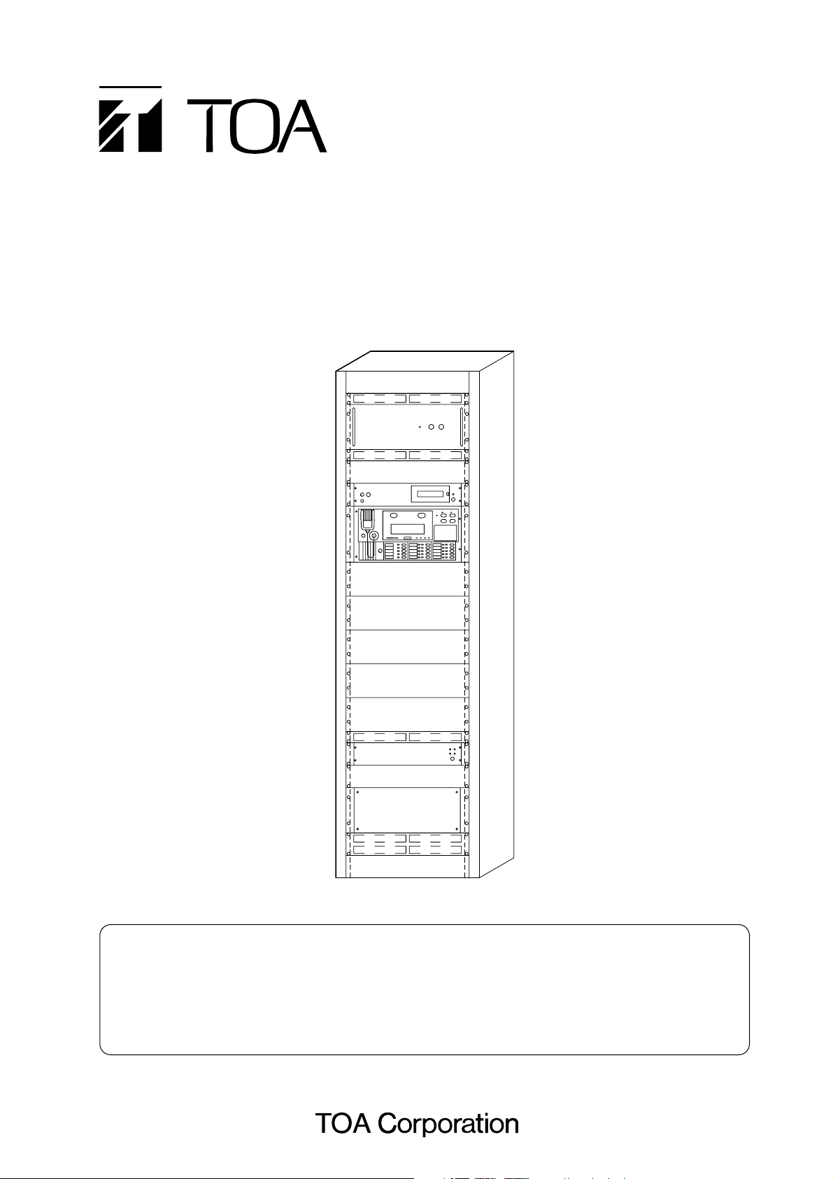
INSTALLATION MANUAL
BASIC INSTALLATION
RACK-MOUNTED EMERGENCY PA SYSTEM
MODEL NUMBERS : FS-971
FS-972
FS-973
FS-970 SERIES
Installation Precautions (For Sales Shops and Installers)
• When inspecting the speaker line insulation, disconnect the speaker lines from the PA system.
• If the system's fire alarm (EL) and fire confirmation signal (EF) terminals are connected during a
dielectric strength test of the relay contact of a fire alarm system or other external systems, this
can cause damage to the PA system.
Page 2

2
1. SAFETY PRECAUTIONS
.............................................................................................................
4
2. SUPPLIED MANUALS
..................................................................................................................
6
3. BEFORE STARTING INSTALLATION
3.1. System Summary ...........................................................................................................................
7
3.2. About the Emergency Power Supply
3.2.1. Selection of the emergency power supply panel and battery ..............................................
8
3.2.2. DC power supply panel expansion ......................................................................................
8
4. NI-CD BATTERY REPLACEMENT
...........................................................................................
9
5. INSTALLATION PROCEDURES
................................................................................................
10
6. EQUIPMENT RACK ASSEMBLY AND INSTALLATION
6.1. Poor Installation Locations ..............................................................................................................
11
6.2. Rack Assembly ...............................................................................................................................
11
6.3. Rack Installation .............................................................................................................................
12
6.4. Securing the Rack CR-272 or CR-412 to the Floor ........................................................................
12
6.5. Securing the Rack CR-412-6 to the Floor ......................................................................................
13
6.6. Securing the Rack to the Wall (for Prevention of the Fall) ..............................................................
13
6.7. Rack Suspension using Eyebolts ...................................................................................................
14
6.8. Fine Height Adjustment of the Installed Rack .................................................................................
14
6.9. Grounding .......................................................................................................................................
14
7. BEFORE MOUNTING THE COMPONENTS IN THE RACK
7.1. Integrated Control Panel EP-0510 ..................................................................................................
15
7.2. Pre-amplifier Panel PP-025B ..........................................................................................................
16
8. COMPONENT INSTALLATION
8.1. Integrated Control Panel .................................................................................................................
18
8.2. Junction Panel ................................................................................................................................
18
8.3. Emergency Power Supply Panel ....................................................................................................
19
8.4. DC Power Supply Panel .................................................................................................................
19
8.5. Power Amplifier Panel Mounting Position .......................................................................................
20
TABLE OF CONTENTS
Page 3

3
9. RACK INTER-PANEL CONNECTION
9.1. FS-971 System Panel Connection Diagram ...................................................................................
21
9.2. Pre-amplifier Panel PP-025B Connection .......................................................................................
22
9.3. Power Amplifier Panel Connection .................................................................................................
23
9.4. Emergency Power Supply Panel DS-029B Connection
9.4.1. Battery connection ...............................................................................................................
24
9.4.2. About the Emergency Power Supply Panel's (DS-029B's) terminals ..................................
24
9.4.3. About the operation of the Emergency Power Supply Panel DS-029B ...............................
25
9.4.4. Connections .........................................................................................................................
27
9.4.5. Connecting a single emergency power supply panel to power amplifiers ...........................
31
9.5. Junction Panel JP-0410 Connection
9.5.1. Connecting the Junction Panel's rear-mounted terminal block ............................................
32
9.5.2. Connecting the AC power supply of the Junction Panel JP-0410 .......................................
33
9.6. DC Power Supply Panel Connection
9.6.1. When the DC power supply panel is not required
(i.e. when you can do with the junction panel's internal power supply).... ...........................
34
9.6.2. When expanding the power supply for external equipment .................................................
35
9.6.3. When expanding the power supply for internal equipment ..................................................
35
9.6.4. Connection between DC power supply panel and Expansion Operation Panel EP-029 .....
36
9.6.5. Connection between DC power supply panel and Expansion Junction Panel JP-039 ........
37
10. SETTING OF THE INTEGRATED CONTROL PANEL EP-0510
......................................
38
11. EXPANSION PANEL ADDRESS SETTING
11.1. Expansion Operation Panel EP-029 .............................................................................................
41
11.2. Expansion Junction Panel JP-039 ................................................................................................
41
12. CONNECTING THE RACK-MOUNTED COMPONENTS TO EXTERNAL LINES
12.1. Names of the Front-Mounted Terminal of the Junction Panel JP-0410 ........................................
42
12.2. AC Power Supply Connections .....................................................................................................
42
12.3. Speaker Connections ...................................................................................................................
43
12.4. Connections to the Automatic Fire Alarm Systems ......................................................................
44
13. CONNECTION INSPECTION
13.1. Inspection of Connections and Wiring ..........................................................................................
45
13.2. Adjustment and Measurement of Power Circuitry
13.2.1. AC line insulation measurement (using megger) ...............................................................
45
13.2.2. Power voltage measurement (using tester) .......................................................................
45
13.3. Speaker Line Adjustment and Measurement
13.3.1. Speaker line impedance measurement (using impedance meter) ....................................
46
13.3.2. Speaker line insulation resistance measurement (Measuring instrument: Megger) ..........
47
13.4. Speaker Sound Pressure Level Measurement .............................................................................
48
14. POWER-ON AND INSPECTION
................................................................................................
48
15. SPECIFICATIONS OF THE MAIN RACK COMPONENTS
................................................
49
Page 4
4
When Installing the Unit
• Do not expose the unit to rain or an environment
where it may be splashed by water or other liquids,
as doing so may result in fire or electric shock.
• Use the unit only with the voltage specified on the
unit. Using a voltage higher than that which is
specified may result in fire or electric shock.
• Do not cut, kink, otherwise damage nor modify the
power supply cord. In addition, avoid using the
power cord in close proximity to heaters, and never
place heavy objects -- including the unit itself -- on
the power cord, as doing so may result in fire or
electric shock.
• Ensure that the voltage selector is properly set to
the local power voltage. Wrong settings may cause
a fire or electric shock.
When the Unit is in Use
• Should the following irregularity be found during
use, immediately switch off the AC breaker and
contact your nearest TOA dealer. Make no further
attempt to operate the unit in this condition as this
may cause fire or electric shock.
· If you detect smoke or a strange smell coming
from the unit.
· If water or any metallic object gets into the unit
· If the unit falls, or the unit case breaks
· If the power supply cord is damaged (exposure of
the core, disconnection, etc.)
· If it is malfunctioning (no tone sounds.)
• To prevent a fire or electric shock, never open nor
remove the unit case as there are high voltage
components inside the unit. Refer all servicing to
your nearest TOA dealer.
• Do not place cups, bowls, or other containers of
liquid on top of the rack. If they accidentally spill
into the mounted units, this may cause a fire or
electric shock.
• Do not insert nor drop metallic objects or
flammable materials in the ventilation slots of the
unit's cover, as this may result in fire or electric
shock.
1. SAFETY PRECAUTIONS
• Be sure to read the instructions in this section carefully before use.
• Make sure to observe the instructions in this manual as the conventions of safety symbols and messages
regarded as very important precautions are included.
• We also recommend you keep this instruction manual handy for future reference.
Safety Symbol and Message Conventions
Safety symbols and messages described below are used in this manual to prevent bodily injury and property
damage which could result from mishandling. Before operating your product, read this manual first and
understand the safety symbols and messages so you are thoroughly aware of the potential safety hazards.
WARNING
Indicates a potentially hazardous situation which, if mishandled, could
result in death or serious personal injury.
Indicates a potentially hazardous situation which, if mishandled, could
result in moderate or minor personal injury, and/or property damage.
WARNING
CAUTION
Page 5

5
When Installing the Unit
• Never plug in nor remove the power supply plug
with wet hands, as doing so may cause electric
shock.
• Do not block the upper panel ventilation slots in the
unit's cover. Doing so may cause heat to build up
inside the unit and result in fire.
• Avoid installing the unit in humid or dusty locations,
in locations exposed to the direct sunlight, near the
heaters, or in locations generating sooty smoke or
steam as doing otherwise may result in fire or
electric shock.
When the Unit is in Use
• Make sure to observe the following handling
precautions so that a fire or personal injury does
not result from leakage or explosion of the battery.
· Do not short, disassemble, heat nor put the
battery into a fire.
· Do not solder a battery directly.
· Be sure to use the specified type of batteries.
· Note correct polarity (positive and negative
orientation) when installing a battery in the unit.
· Avoid locations exposed to the direct sunlight,
high temperature and high humidity when storing
batteries.
CAUTION
Page 6
6
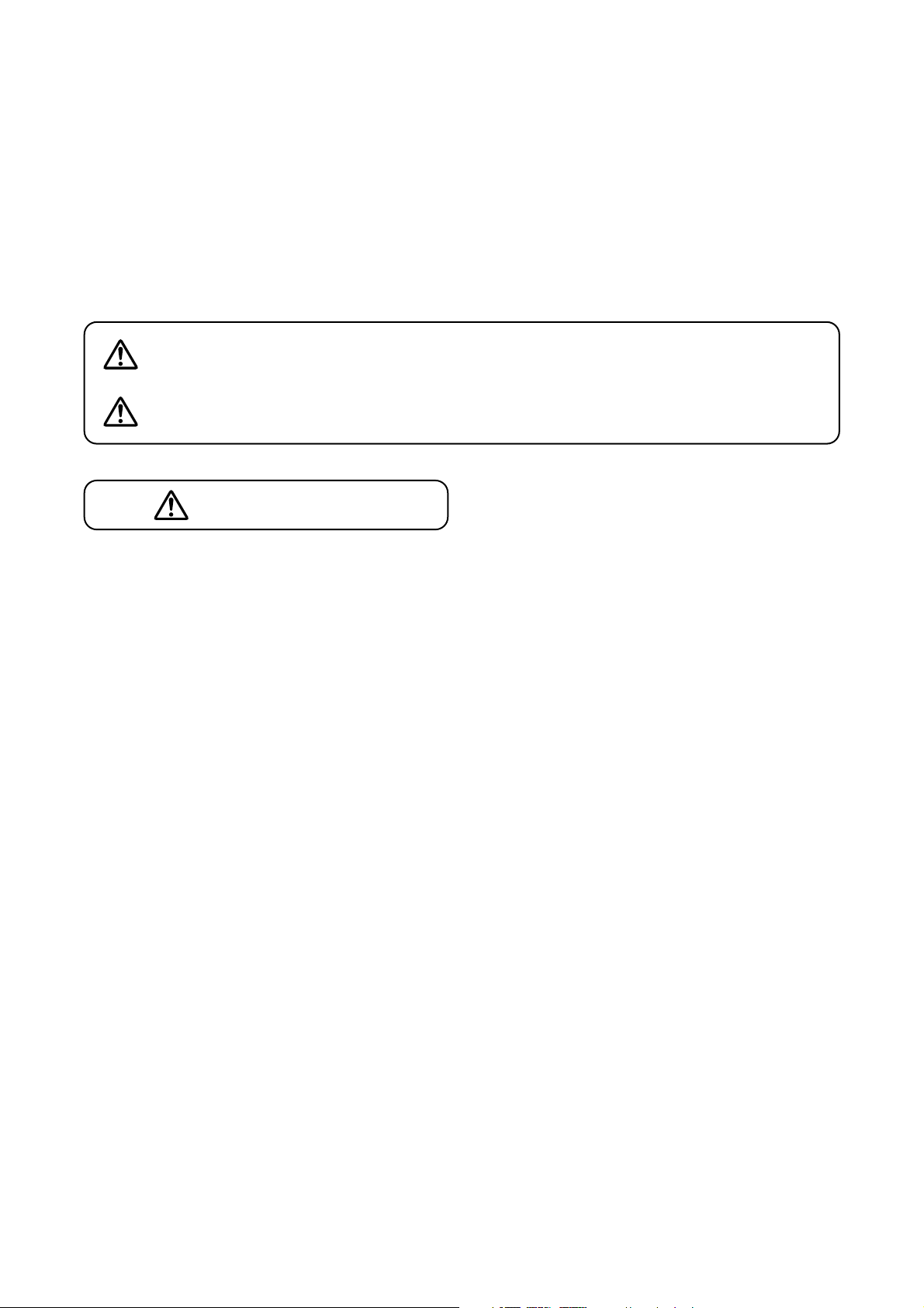
2. SUPPLIED MANUALS
The following manuals are supplied with the emergency PA system.
Emergency PA System FS-970 Series
Installation Manual
Emergency PA System FS-970 Series
Installation Manual - Basic Installation
The book you are reading now
• Read only the manuals that are suited for your purpose.
· Those who operate the PA system to
make both emergency and general
broadcasts
Instruction Manual
· Function
· Operation
· Routine inspection
· Overall inspection
Installation manual
(Basic installation)
· Installation
· The basics of installation
and its inspection
Installation manual
(Writing)
· Initialization
· Registration setting
· Setting registration chart
· Those who install the emergency PA
system
· Those who settle on a plan of use,
such as broadcast zone assignment,
and write (register) data
· Those who check system operations
Emergency PA System FS-970 Series
Installation Manual - Applied Installation
Installation manual
(Applied installation)
· Associated equipment
connections
· Reference items
Emergency PA System FS-970 Series
Installation Manual - Writing
The book you are reading now
1
12233
4
4
Page 7
7
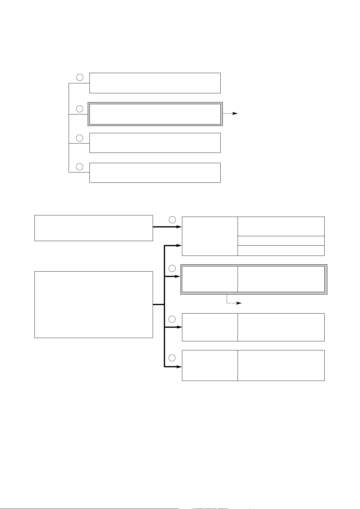
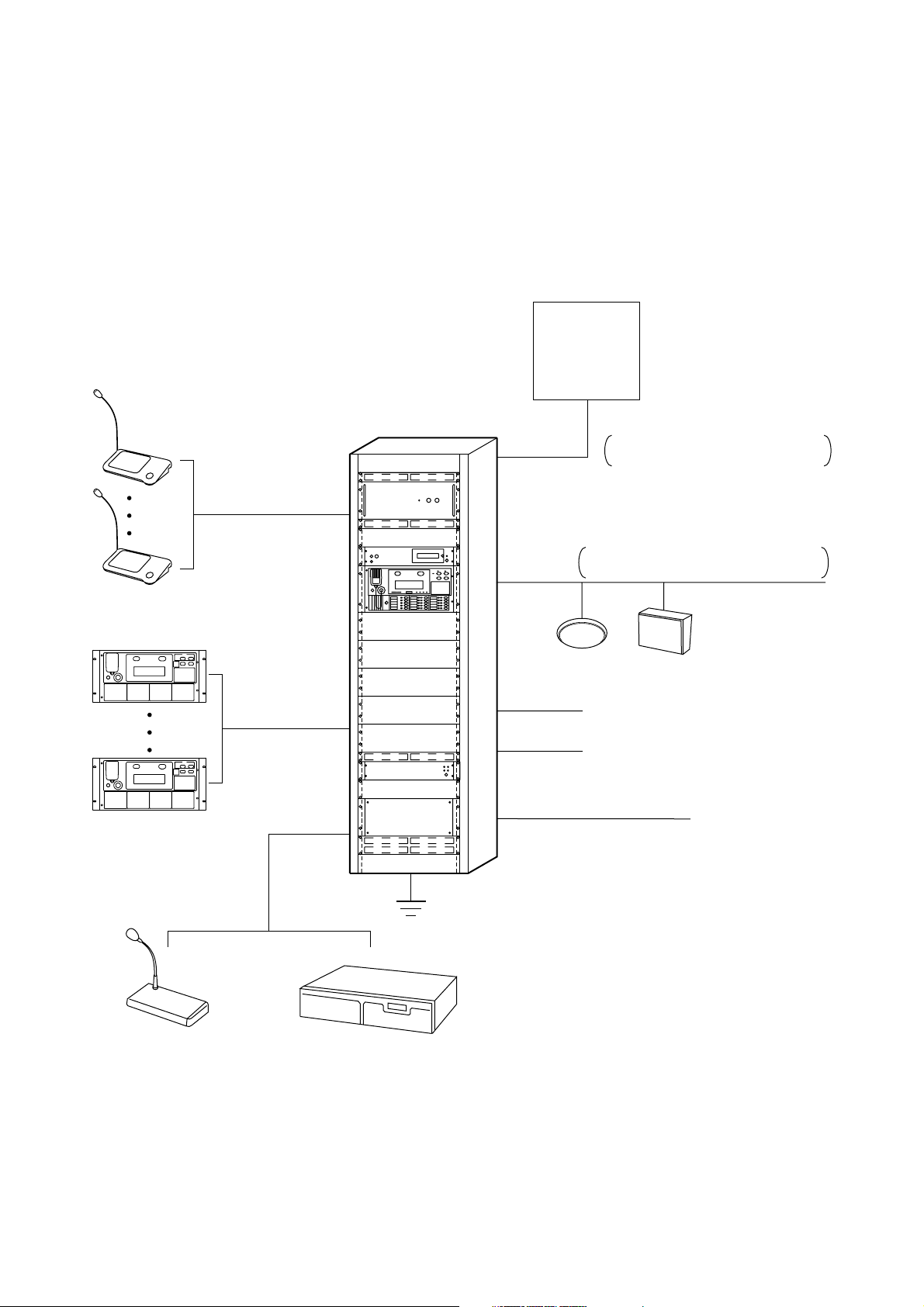
3. BEFORE STARTING INSTALLATION
3.1. System Summary
• The FS-971 and FS-973 permit system expansion of up to 330 lines and up to 330 emergency zones.
• The FS-972 permits system expansion of up to 50 lines and up to 50 emergency zones.
• Each of the FS-971, FS-972 and FS-973 permits connection of eight emergency remote control units and
eight general remote control units.
Fire alarm system
No. of emergency zones
FS-971/FS-973 types: Up to 330 zones
FS-972 type : Up to 50 zones
General remote control unit
(RM-1200)
Up to 8 units
Emergency remote
control unit
(RM-971)
Up to 8 units
AUX control terminal
(15 terminals)
Grounding
Speaker line
Power cable
(Power supply solely intended
for emergency PA systems)
FS-971 and FS-973 types: Up to 330 lines
FS-972 type : Up to 50 lines
Emergency power supply control unit
Speaker controller
110/220 VAC (50/60 Hz)
Remote Microphone
Music playing machine
Page 8
8
3.2. About the Emergency Power Supply
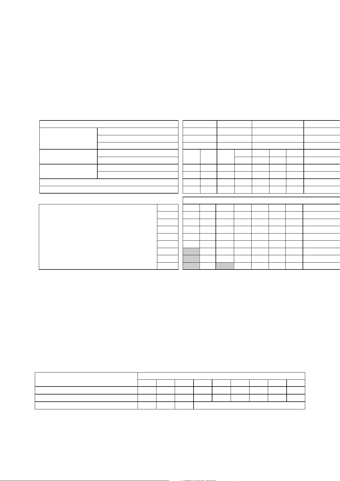
3.2.1. Selection of the emergency power supply panel and battery
The emergency PA system is designed to operate on both the main power supply and emergency power
supply. Because the emergency system needs to be operated for ten minutes or more during a power failure,
the emergency power supply suited to the system scale is required. The FS-970 series systems require the
emergency power supply panel DS-029B and Ni-Cd battery NDC-2435 or NDC-2460. The following table
provides guidelines on the number of emergency power supply panels and Ni-Cd batteries necessary for the
system.
Expansion power supply
AD-011
AD-031B
None (JP-0410's internal power supply only)
Rated output
No. of connected emergency remote control units
PA-1230B
PA-2440B
PA-3640B
0
1
2
3
4
5
6
7
8
Power amplifier panel
composition
Operation section/control section
Power amplifier panel
Battery composition
Quick reference table for emergency battery composition
No. of zones of the main rack and emergency remote control unit
NDC-2435
NDC-2460
Battery
No. of emergency power supply panels DS-029B
50
30
30
20
10
10
120
90
70
60
50
40
30
30
30
60
40
30
30
20
10
10
10
180
150
120
100
90
70
60
50
50
330
270
220
190
160
140
130
110
100
330
310
260
220
190
170
150
140
120
330
330
330
330
330
310
280
250
230
3.5AH
1
1
a
1
1
a
6AH
120W
1
6AH
1
1
a
3.5AH
3.5AH
2
1
b
6AH
6AH
2
1
b
7AH
6AH
2
1
2
c
12AH
6AH
3
2
c
240W
1
360W
1
Notes
• This table assumes that the main rack system and emergency remote control unit are identical in the
number of broadcast zones. It is also assumed that no other components are connected other than the EP029, EP-0510, EP-059R, JP-039, and JP-0410, and that any component is not connected to the emergency
power-off output or emergency output. In some systems, the number of zones may be less than those
shown in the above table.
• Refer to the connection examples on p. 27-30 for connection methods a-d of the Emergency Power Supply
Panel DS-029B.
3.2.2. DC power supply panel expansion
When multiple operation sections or emergency remote control units are connected to the main rack, the DC
power supply panel is required in addition to the Emergency Power Supply Panel DS-029B. For its
connection, refer to "DC Power Supply Panel Connection" on p. 34.
0 unit
70
160
30
Maximum zone Nos. vs. connected remote control unit Nos.
1 unit
50
130
20
2 unit
40
100
10
3 unit
30
80
4 unit
30
70
5 unit
20
60
6 unit
10
50
7 unit
10
50
8 unit
10
40
Note
Depending upon the connection method of the JP-0410's internal power supply/ expansion power supply to
expansion equipment (EP-029, EP-059R, JP-039, etc.), the number of zones may lower those shown in the
above table. When using other combinations not shown in the table, contact the shop from where you
purchased the unit.
Expansion power supply is required.
Connection of emergency power supply panel DS-029B
Page 9
9
330
270
220
190
160
140
130
110
100
330
310
260
220
190
170
150
140
120
330
330
330
330
330
310
280
250
230
330
270
220
190
160
140
130
110
100
330
310
260
220
190
170
150
140
120
330
330
330
330
330
310
280
250
230
330
270
220
190
160
140
130
110
100
330
310
260
220
190
170
150
140
120
330
330
330
330
330
310
280
250
230
330
270
220
190
160
140
130
110
100
330
310
260
220
190
170
150
140
120
330
330
330
330
330
310
280
250
230
330
270
220
190
160
140
130
110
100
330
310
260
220
190
170
150
140
120
330
330
330
330
330
310
280
250
230
No. of zones of the main rack and emergency remote control unit
140
110
90
70
60
50
40
40
30
6AH
7AH
2
1
2
c
7AH
7AH
4
2
c
12AH
7AH
2
2
2
c
6AH
12AH
3
2
c
7AH
12AH
2
2
2
c
12AH
12AH
4
2
c
6AH
18AH
4
2
d
7AH
18AH
2
3
3
c
12AH
18AH
6
3
c
2
1
b
6AH
24AH
5
3
c
7AH
24AH
2
4
3
c
12AH
24AH
6
3
c
6AH
30AH
6
3
d
12AH
30AH
7
4
c
7AH
30AH
2
5
4
c
480W
2
720W
2
1080W
3
1440W
4
1800W
5
12AH
4. NI-CD BATTERY REPLACEMENT
Emergency Power Supply Panel DS-029B
Ni-Cd battery
Connector
Front panel mounting screw
Front panel
1. Remove battery connectors.
2. Take the batteries out of the battery compartment.
CAUTION
• Do not short-circuit or disassemble the Ni-Cd
battery. Also, do not expose it to excessive heat
or throw it into a fire.
• To prevent short-circuiting of removed Ni-Cd
batteries, wrap electrical tape around their
terminals.
• Do not use the Ni-Cd batteries in combination
with dry batteries or other types of battery.
• When replacing the Ni-Cd battery, only use the
type designated in the section "About the
Emergency Power Supply" on p. 8.
Page 10
10
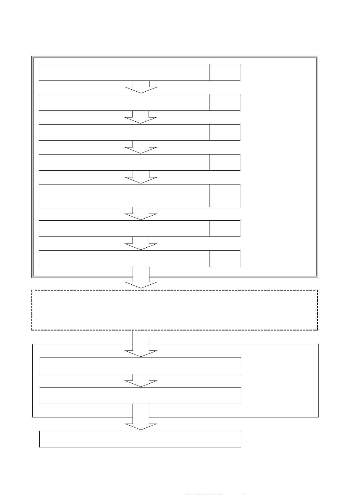
End
"Basic Installation Manual"
you are reading now
Separate book
"Writing"
• Finish construction work explained in the separate book "Applied
Installation" together with construction work explained in the
"Installation Manual-Basic Installation.
• When there is no applicable construction work, advance to writing.
Separate book
"Applied Installation"
2. Writing
1. Data Initialization
1. Equipment rack assembly and installation Page 11
2. Before installing rack components in the rack Page 15
3. Rack component mounting Page 18
4. Rack inter-component connections Page 21
5. Operation/expansion panel address setting and connection
to external lines
6. Connection inspection Page 45
7. Power on and check Page 48
5. INSTALLATION PROCEDURES
Page 38
Page 11
11
6. EQUIPMENT RACK ASSEMBLY AND INSTALLATION
6.1. Poor Installation Locations
Avoid installing the rack in the following locations.
• Locations that may be exposed to fire, heat or direct sunlight (ambient temperature should be between 0°C
and 40°C).
• Locations that may be exposed to rainwater, steam or high humidity.
• Locations exposed to vibration.
• Locations offering limited space at the rear of the rack for inspection.
• Locations where particles of metal or dust accumulate, or near chemicals or oil.
• Locations near high-voltage equipment or equipment sensitive to electro-magnetic fields.
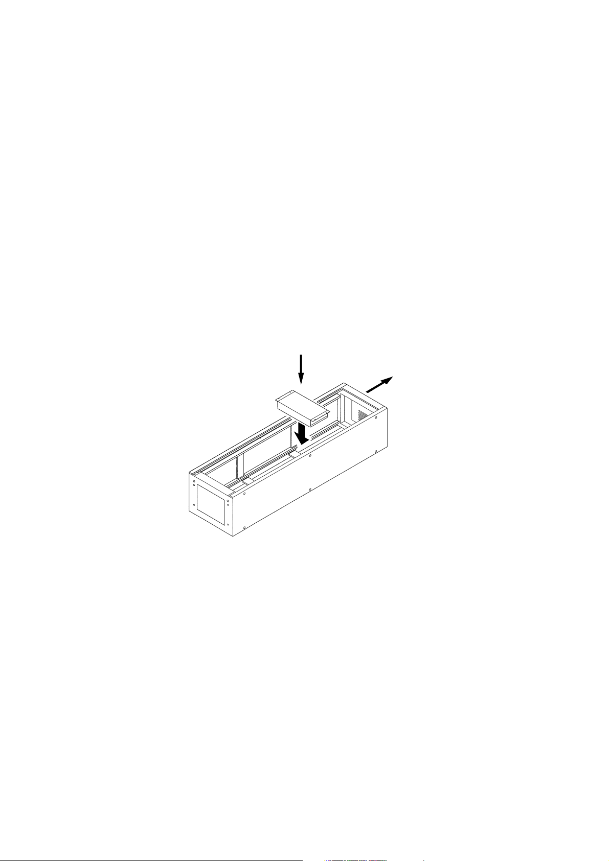
6.2. Rack Assembly
• Follow the instructions in the manual attached to the rack to assemble.
• When installing the rack components, lay the rack down face-up as shown in the figure to facilitate work and
ensure safety. (For component installation, refer to Component Installation on p. 18.)
• Install the Blower Unit BU-412 after rack assembly completion but before installing each rack component.
Note
Some components require their functions to be readjusted before they are installed in the rack. In such cases,
install the components after readjustment completion. (Refer to p. 15.)
Front
Ceiling
Page 12
12
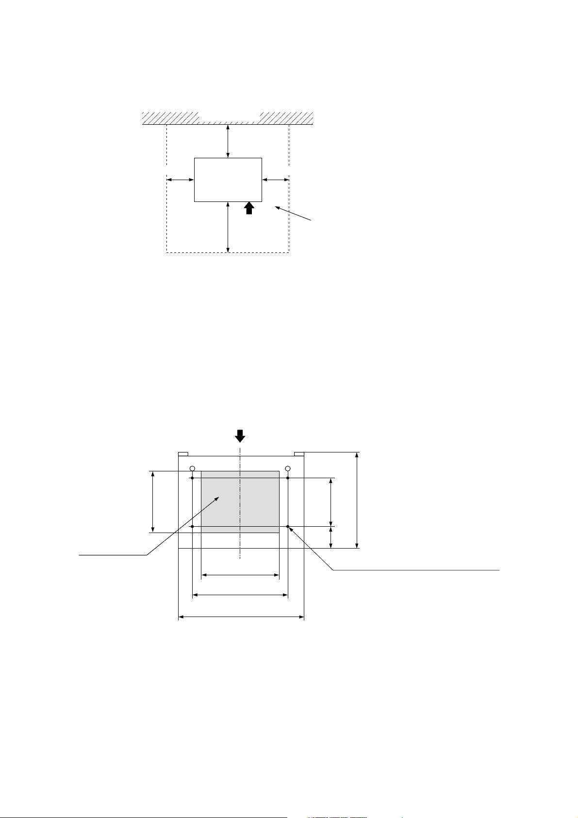
6.3. Rack Installation
The emergency rack system must be installed as shown in the figure below.
• To prevent the equipment rack from falling down due to an earthquake, etc., secure the rack to the floor with
anchor bolts and to the wall with brackets.
• When installing the general rack system, also allow for the above spacing to facilitate maintenance.
6.4. Securing the Rack CR-272 or CR-412 to the Floor
Four anchor bolt mounting holes (ø15 mm) are provided in the rack bottom surface to secure the rack to the
floor. Referring to the figure below, make holes in the floor, then secure the rack to the floor using four M10M12 anchor bolts.
Wall surface, etc.
Over 0.6 m
Front
Over 0.5 m
Space for inspection and operation
Over 0.5 m
Over 2 m
CR-272
CR-412
CR-412-6
Front
Cable entry opening
280
360
440
566
220100
435
Anchor bolt mounting hole (ø15 mm, 4 places)
Page 13
13
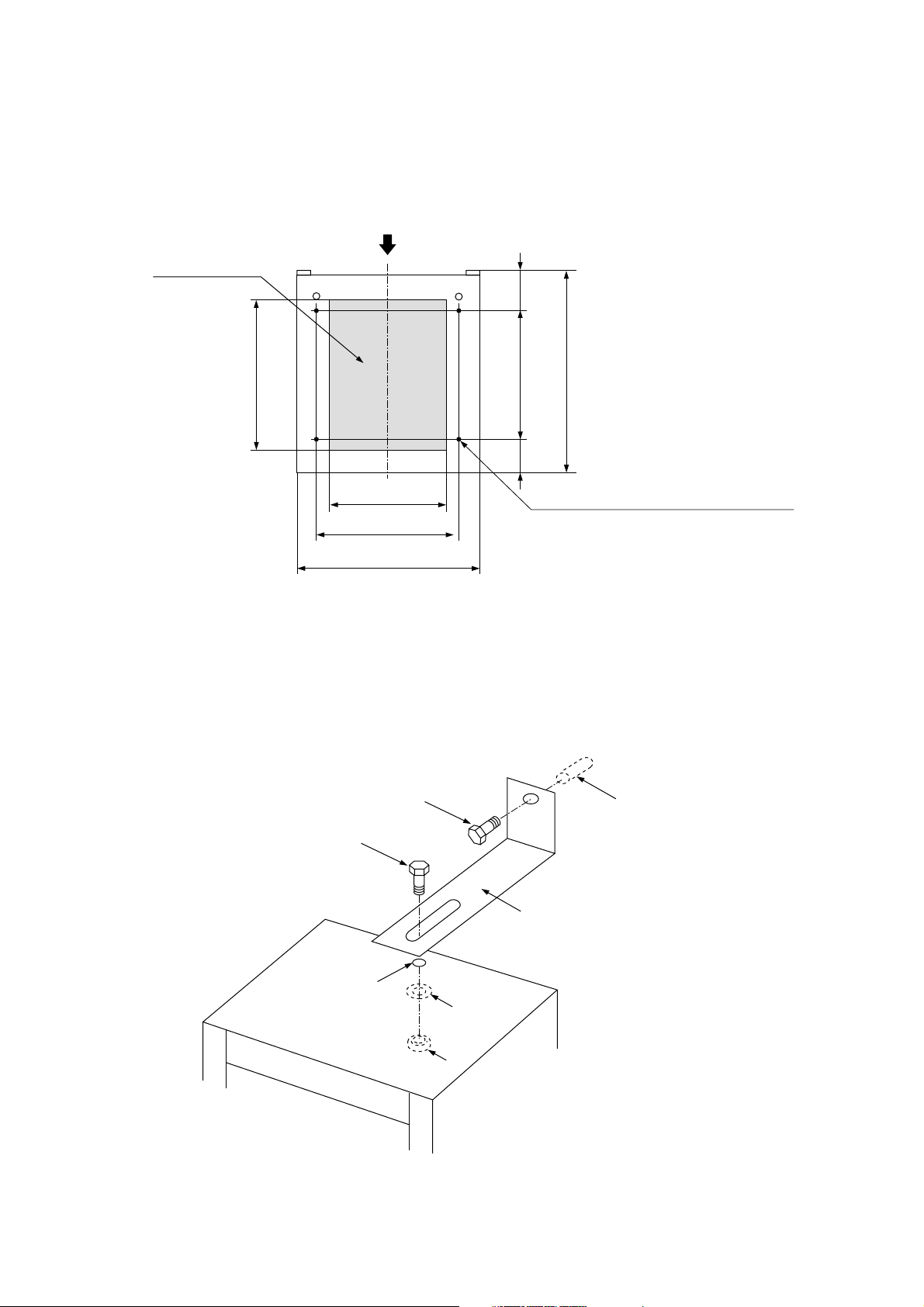
6.5. Securing the Rack CR-412-6 to the Floor
Four anchor bolt mounting holes (ø15 mm) are provided in the rack bottom surface to secure the rack to the
floor. Referring to the figure below, make holes in the floor, then secure the rack to the floor using four M10M12 anchor bolts.
Front
460
400
615
(115)
100
360
440
566
Anchor bolt mounting hole (ø15 mm, 4 places)
Cable entry opening
6.6. Securing the Rack to the Wall (for Prevention of the Fall)
A knock-out hole (ø6.5 mm) is provided on the rack top panel. Break this hole with a screwdriver, and secure
the rack to the wall by installing a bracket in the exposed hole. (Note the bracket is not supplied with the
system. Purchase it separately in the market.)
Washer
Knock-out hole
Nut
Bracket
M6 bolt
Anchor
Bolt
[Installation example]
Page 14
14
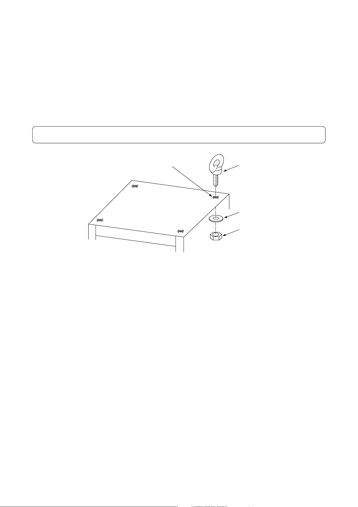
6.7. Rack Suspension using Eyebolts
Eyebolts for suspension can be mounted to the rack top panel.
• Purchase the following parts separately in the market.
Eyebolts M16 ............... 4 pieces
Nut M16 ....................... 4 pieces
Plain washer M16 ........ 4 pieces
Remove four rubber hole covers provided on the top panel, and install eyebolts (4 places) in the exposed
holes as shown in the figure.
Important: The maximum rack system weight for 4-point suspension is 300 kg.
6.8. Fine Height Adjustment of the Installed Rack
When the rack installed on the floor is unstable and shaky, make fine adjustment of its height by turning
clockwise the height adjustment screw located in the front of the bottom rack base. Use the standard
screwdriver for adjustment.
6.9. Grounding
Provide grounding terminals using three grounding terminal screws (M5) located at the rear of the bottom rack
base. Three female screws (M5) are located in the front of the base. Use these screws as required.
Remove this rubber hole cover.
Top panel of the CR-272,
CR-412 and CR-412-6
Eyebolt
Plain washer
Nut
Page 15
15
7. BEFORE MOUNTING THE COMPONENTS IN THE RACK
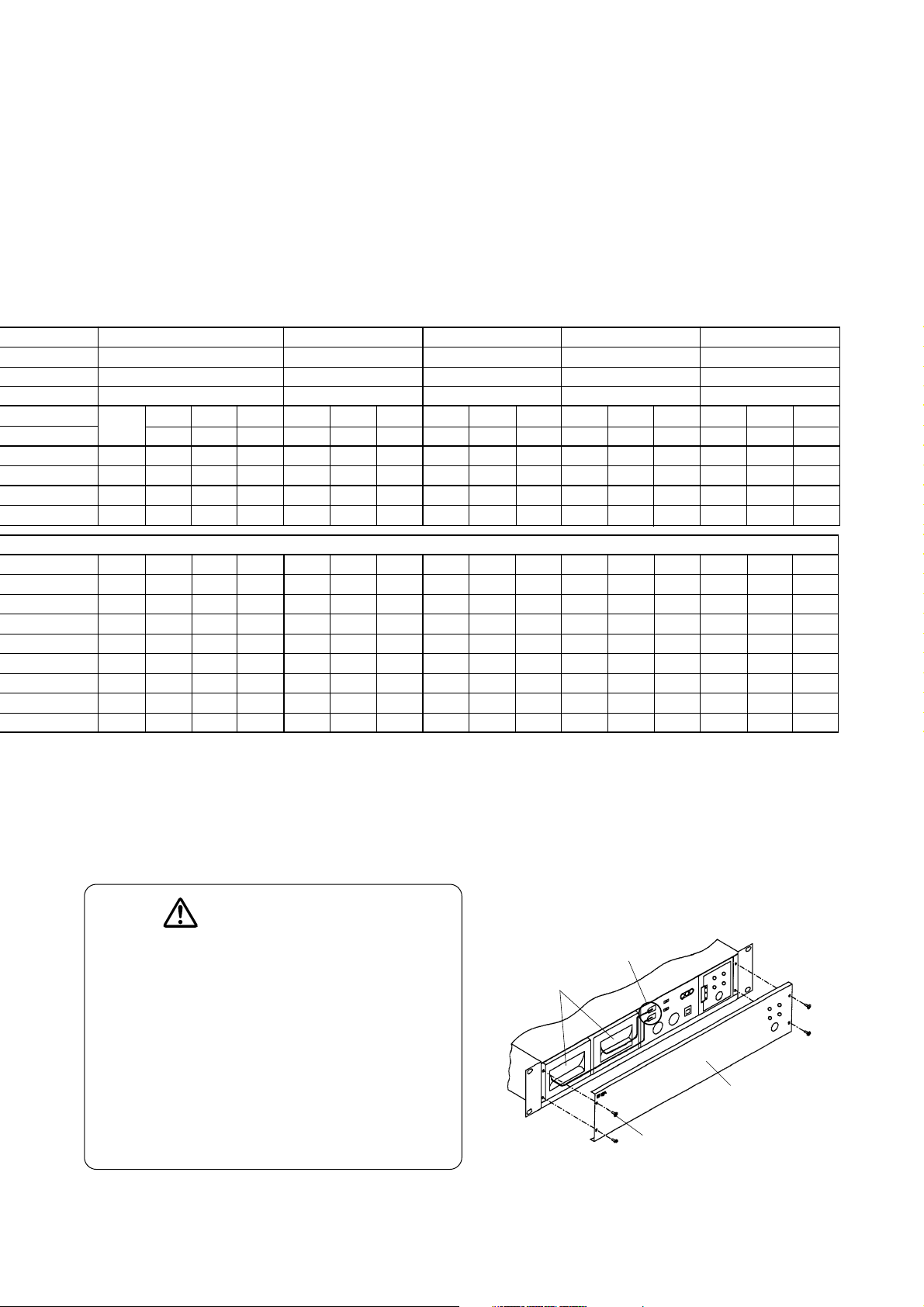
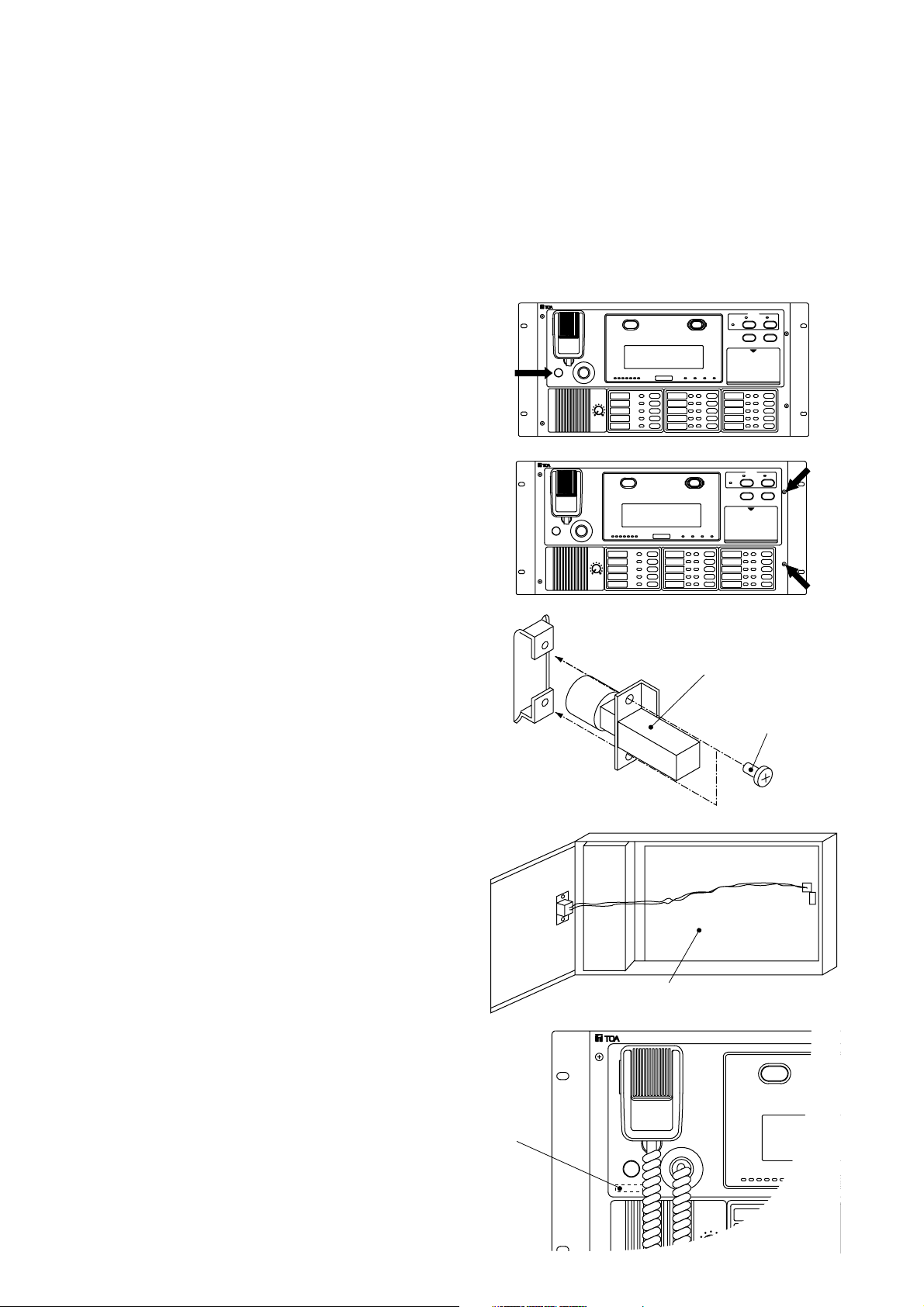
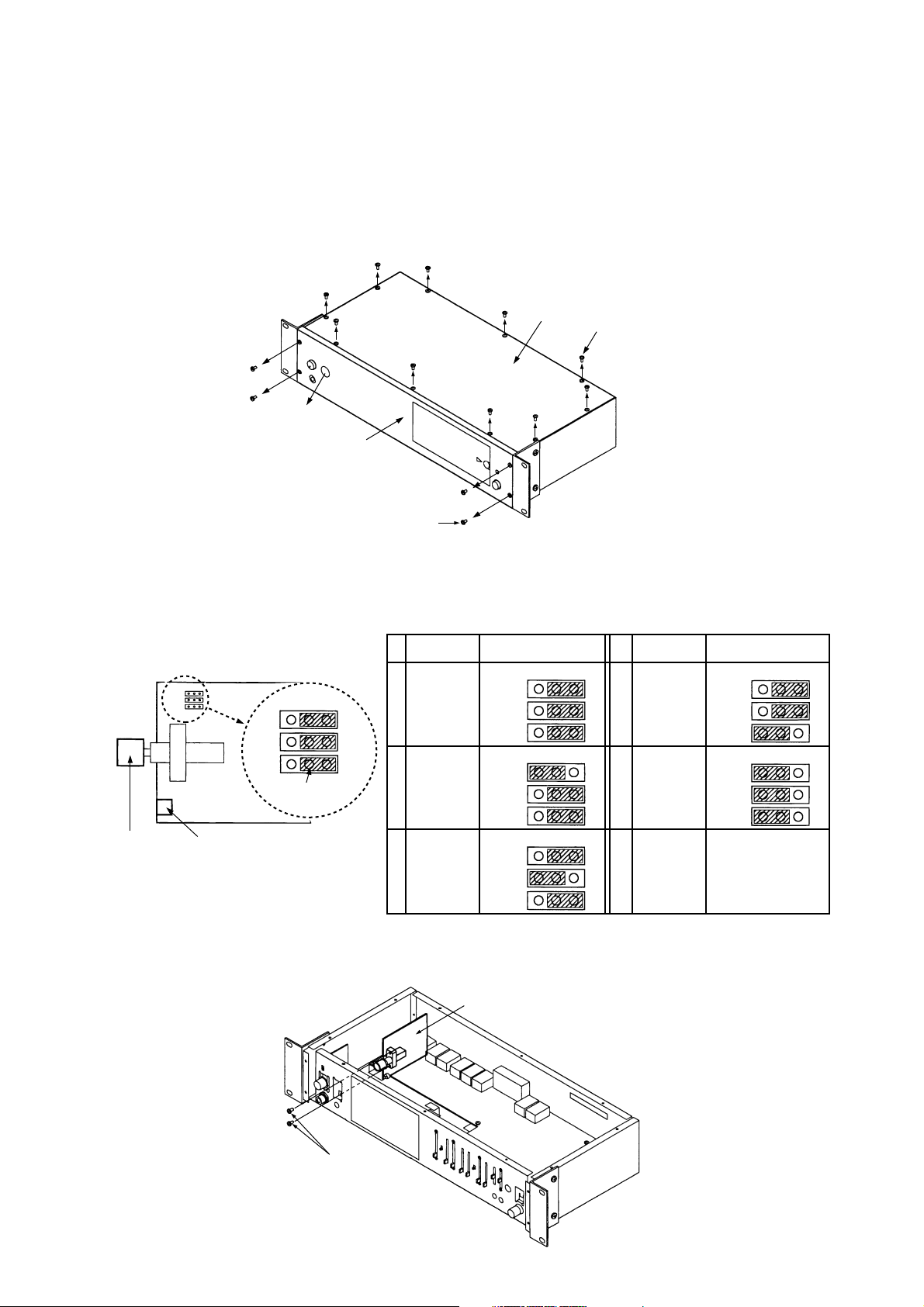
7.1. Integrated Control Panel EP-0510
• Chime Switch Installation
To activate the external chime device or the CK-025 Chime Unit built in the PP-025B Pre-amplifier, install the
chime switch (supplied with the EP-0510) as shown below. You may skip the following installation procedures
if the chime does not need to be activated from the EP-0510.
Supplied label
1. Push to break the chime switch hole on the
Operation Panel.
2. Remove two screws on the right of the
Operation Panel and open the panel.
3. Mount the chime switch to the inside of the
front panel using the supplied screws (3x6).
4. Connect the chime switch connector to CN8
on the control circuit board.
5. Attach the supplied label to the Operation
Panel.
Chime switch
Screw (3x6)
Mount from the back of the panel.
CN8
Control circuit board
Page 16
16
Screw (M3x6)
Chime Unit CK-025
7.2. Pre-amplifier Panel PP-025B
• Chime Unit (CK-025) Installation
Note: Install the Chime Unit in the Pre-amplifier Panel before mounting the Pre-amplifier Panel in the rack.
1. Remove the front panel, top panel and rubber hole cover on the front panel.
2. Select the chime tone type for the Chime Unit to install by changing the jumper connector position on JP1
through JP3 on the Chime Unit's circuit board.
3. Mount the Chime Unit and secure it using two screws (M3x6) supplied with the Chime Unit.
Hole cover
Front panel
Screw (M3x6)
Top panel
Screw (M3x6)
Jumper connector
position
21
JP 1
JP 2
JP 3
21
JP 1
JP 2
JP 3
21
JP 1
JP 2
JP 3
Chime switch Chime volume control
21
JP 1
JP 2
JP 3
Jumper connector
Chime tone Chime tone
1
Ascending
4-tone chime
2
Two tone
chime
3
Gong
Jumper connector
position
21
JP 1
JP 2
JP 3
21
JP 1
JP 2
JP 3
21
JP 1
JP 2
JP 3
4
Single tone
chime
5
Descending
4-tone chime
Page 17
17
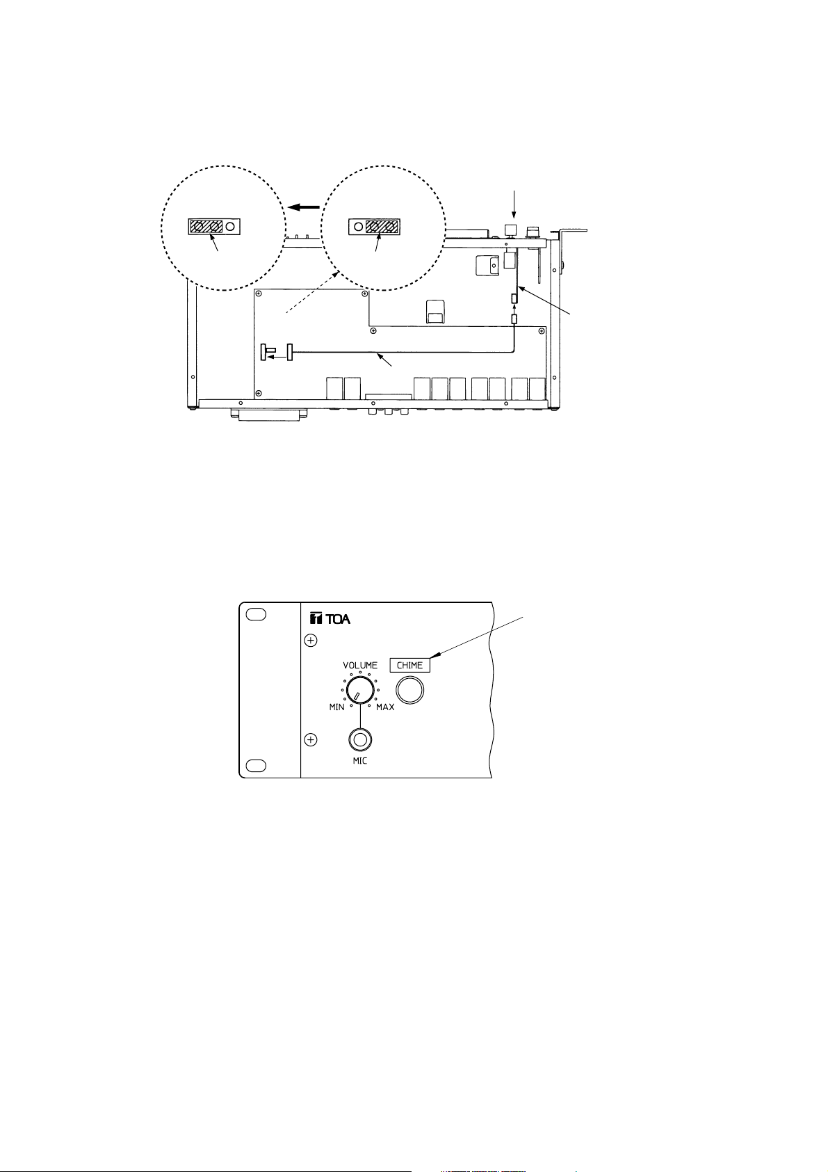
4. Connect one end of the connector cable supplied with the Chime Unit to the Chime Unit' s connector, and
the other end to connector CN17 on the PP-025B's internal circuit board.
JP1
CHIME SET
USE NO USE
Jumper connector
JP1
CHIME SET
USE NO USE
Jumper connector
Front
JP1
CHIME
SET
CN17
CHIME
Connector cable supplied with
the CK-025
Chime Unit CK-025
Chime Unit is used.
(USE position)
Chime Unit is not used.
(NO USE position)
5. Remove JP1 jumper connector on the PP-025B's internal circuit board and reset it to the USE position.
6. Replace both the front and top panels, and attach "CHIME" label (included in the supplied input indication
labels) to the position above the chime switch.
"Chime" label
Page 18

18
8. COMPONENT INSTALLATION
This section describes the points of installation you need to bear in mind when mounting the following main
components in the rack.
8.1. Integrated Control Panel
It is highly recommended that all the switches on the emergency operation panel be positioned at the height of
0.8 to 1.5 m from the floor. Therefore, the Integrated Control Panel EP-0510 and the Expansion Operation
Panels EP-029-10 and EP-029-20 must be positioned at the height shown below. When exceeding such
height ranges, install them in multiple racks and arrange those racks side by side.
Installation
height range
Under
10-unit size
Over
17-unit size
27-unit size
CR-272 rack
Capacity: 50 emergency broadcast zones
Installation
height range
Under
15-unit size
Over
17-unit size
Over 9-unit size
41-unit size
Over 0.8 m
Under 1.5 m
CR-412/-412-6 rack
Capacity: 110 emergency broadcast zones
One integrated control panel (5U) and
up to 2 expansion operation panels
(2U) are mountable.
One integrated control panel (5U) and
up to 5 expansion operation panels
(2U) are mountable.
The above figures show that the racks are installed directly on the floor. When using a channel base, ensure
that all the switches on the emergency operation panel are positioned at the height of 0.8 to 1.5 m from the
floor.
8.2. Junction Panel
• It is preferable to mount the perforated panel, such as the PF-023B, in the lowermost position of the rack,
and mount the Junction Panel JP-0410 above it. This facilitates connection of external wires.
• When mounting the Expansion Junction Panel JP-039-10 or JP-039-20 in the rack, mount it below the JP-
0410.
Page 19

19
8.3. Emergency Power Supply Panel
You need to mount the perforated panel (PF-013B, etc.) above and below each Emergency Power Supply
Panel DS-029B. However, up to two Emergency Power Supply Panels may be stacked without the perforated
panel between them.
Equipment rack
Emergency Power Supply Panel
Perforated Panel
Equipment rack
Emergency Power Supply Panel
Perforated Panel
8.4. DC Power Supply Panel
• The above-mentioned basic installation method of the Emergency Power Supply Panel also applies to the
installation of the DC Power Supply Panels AD-011 and AD-031B.
• The Rack Supporting Runner YA-706 is attached to the AD-031B. When installing it, follow the instructions
in the equipment rack installation manual.
Page 20

20
8.5. Power Amplifier Panel Mounting Position
• You need to mount the perforated panel (PF-013B, etc.) above and below each power amplifier panel.
However, up to two power amplifier panels may be stacked without the perforated panel between them
provided each amplifier output power is less than 120 W.
• Mounting examples
1. Power amplifier panel rated at 120 W or less (PA-1230B)
Equipment rack
Power amplifier panel
Perforated panel
2. Power amplifier panel rated at 240 W or more (PA-2440B and PA-3640B)
Equipment rack
Power amplifier panel
Perforated panel
• Rack Supporting Runner for the power amplifier panel
When installing the power amplifier panel PA-1230B, PA-2440B or PA-3640B, be sure to follow the
instructions in the Equipment Rack Installation Manual and attach the optional guide rail YA-706 to the rack.
Page 21

Supplied Connection Cables
Power cord, parallel vinyl covered cable, dual phone plug balanced cable
Dual phone plug balanced cable
Dual phone plug balanced cable, PP-JP control/power connector cable
EP-EP control connector cable, EP-EP power connector cable
Power cord, parallel vinyl covered cable (long cable x 1, short cable x 3), junction connector cable
JP-EP control connector cable, JP-EP power connector cable
JP-JP control connector cable, JP-JP power connector cable
21
9. RACK INTER-PANEL CONNECTION
9.1. FS-971 System Panel Connection Diagram
Component Model No.
PA-3640B
PP-025B
EP-0510
EP-029-20
DS-029B
JP-0410
JP-039-20
<Parallel vinyl covered cable>
Supplied with DS-029B.
Supplied with PA-3640B.
<JP-JP power
connector cable>
Supplied with
JP-039.
<Junction connector cable>
Supplied with DS-029B.
<Power cord>
Supplied with
DS-029B.
<EP-EP power connector
cable> Supplied with
EP-029.
<Power cord> Supplied with PA-3640B.
<PP-JP control/power connector cable> Supplied with EP-0510E.
<Parallel vinyl covered cable> Supplied with PA-3640B.
<Parallel vinyl covered cable> Supplied with DS-029B.
<Dual phone plug cable>
Supplied with PP-025B.
<JP-EP power connector cable> Supplied with JP-0410.
<EP-EP control connector
cable> Supplied with EP-029.
<Dual phone plug balanced cable>
Supplied with EP-0510.
<JP-EP control connector cable>
Supplied with JP-0410.
PA-3640B
PP-025B
EP-0510
EP-029-20
DS-029B
JP-0410
JP-039-20
<JP-JP control
connector cable>
Supplied with JP-039.
FS-971-36NA
Page 22

22
9.2. Pre-amplifier Panel PP-025B Connection
• You can install the Chime Unit in the Pre-amplifier Panel. (Refer to p. 16.)
• Input 1-A jack is located on both the front and rear panels. When both jacks are simultaneously used, the
broadcast from the front panel is allowed to go through.
• Input 1 takes precedence over Inputs 2 and 3, while Input 2 takes precedence over Input 3. Connect a BGM
player to Input 3, and the microphone and chime to Input 1 or 2 depending on the degree of their
importance. Use the muting volume control located in the front panel to adjust attenuation levels. Priority is
controlled by the external control signal from the control connector or by an input signal level. Should the
latter be the case, when the volume of the input signal is low, control may not be performed effectively. In
such a case, use the external control. Refer to the separate "Installation Manual - Writing" for the method by
external control.
• Line Output 2 is a dedicated output terminal for Input 3. Use this output to make multi-origination broadcast
by separating BGM zones from microphone announcement zones.
Supplied with PP-025B.
EP-0510 rear panel
PRE-AMP IN
JP-0410 rear panel
PP-025B power
PP-025B control
Supplied with EP-0510E.
Page 23

23
9.3. Power Amplifier Panel Connection
• Use the same output line voltage when connecting power amplifier panels for parallel operation. You can
connect up to three power amplifier panels of the same kind in parallel.
Important: Make connection so that the total of speaker rated input power is less than 1 kW for a group of
five consecutive speaker lines (i.e. lines 1-5, 6-10, etc.).
• Do not use the 4 Ωoutput terminal for the rack PA system.
• Refer to p. 24 "Emergency Power Supply Panel DS-029B Connection" for details of the connection to the
emergency power supply panel.
• The junction panel's C1 and H1 are input terminals for speaker lines 1-5, and C2 and H2 are for speaker
lines 6-10. When the panel is supplied from the factory, the input terminals are short-circuited between C1
and C2 and between H1 and H2 by means of a jumper wire. Also, because the monitor circuit is connected
to between C1 and H1, the monitor panel is additionally required for monitoring speaker lines 6-10 when
using the input terminals by separating C1 and H1 from C2 and H2.
Supplied with power
amplifier panel.
Supplied with power amplifier panel.
Supplied with power amplifier panel.
Supplied with power amplifier panel.
Supplied with EP-0510.
Supplied with DS-029B.
Supplied with DS-029B.
Power amplifier panel rear panel
Power amplifier panel rear panel
EP-0510 rear panel
DS-029B rear panel
JP-0410 rear panel
Page 24

24
9.4. Emergency Power Supply Panel DS-029B Connection
9.4.1. Battery connection
Internal Ni-Cd batteries are optional. Depending upon the output and number of power amplifier panels to use,
and the number of connected emergency remote control units, select the proper type of battery. After installing
the selected battery in the DS-029B, make connections. For battery selection, refer to p. 8 "About the
Emergency Power Supply".
After battery installation, connect the battery connector and set the battery using the battery selector switch
located on the right of the battery connector.
When using the NDC-2435, set the switch to the "3500 mAh" position.
When using the NDC-2460, set the switch to the "6000 mAh" position.
When not connecting any battery, set the switch to the OFF position.
OFF3500 mAh 6000 mAh
CHARGE CURRENT
Important
• The emergency PA system automatically checks the battery voltage every 24 hours. Therefore, if you set the
switch to the "3500 mAh" or "6000 mAh" position without connecting the battery, a warning tone is sounded
simultaneously with the battery error indication.
• Note that pressing the DS-029B's check key immediately after the system has been installed and the power
supplied may display the battery error indication.
• To check the battery manually, charge the battery for 24 hours or more before checking.
9.4.2. About the Emergency Power Supply Panel's (DS-029B's) terminals
REMOTE (left) (+, –) terminals
• These terminals supply power for making emergency broadcast when the activation of the fire alarm terminal
or the depression of the emergency key is detected while the system is in standby mode due to a power
failure. They also supply power to the operation/control section in emergency broadcast mode.
• 24 VDC is output when the supply of AC power stops. It is not output while the AC power is supplied.
(Outputs from two batteries 1 and 2 installed in the DS-029B are combined into one 24 VDC output through
a diode.)
• These terminals are connected to both the [EMG DS CTRL (+)] and [GND] terminals of the terminal block on
the rear panel of the Junction Panel JP-0410.
OUTPUT (+, –) terminals
• Output 24 VDC when there is a 24 VDC input to the [REMOTE (right) (+, –)] terminal while the supply of AC
power stops. Note that the 24 VDC power is not output while the AC power is supplied or the system is in
standby mode due to a power failure.
• Outputs 1 and 2 provide 24 VDC from Battery 1, and Outputs 3 and 4 provide it from Battery 2.
• The OUTPUT terminals connect to the power amplifier panel's [24 VDC INPUT (+, –)] terminals.
REMOTE (right) (+, –) terminals
• When these terminals receive 24 VDC while the supply of AC power stops, 24 VDC is output from output
terminals 1-4. Note that the 24 VDC power is not output from output terminals 1-4 even if the 24 VDC power
is input when the AC power is supplied.
• REMOTE (right) terminals connect to the [EMG DS ACTI (+)] and [GND] terminals of the terminal block on
the JP-0410's rear panel.
Page 25

25
9.4.3. About the operation of the Emergency Power Supply Panel DS-029B
When the AC power is supplied and the Emergency Activation terminal is not shorted (standby
status)....
Current flows in coils D and E, and contact points d and e are as shown below. 24 VDC is not sent to
REMOTE (left) or outputs 1-4.
AC power
D
E
DS-029B
Charging
circuit
Battery 1
Battery 2
b
c
e
Output 1
Output 2
Output 3
Output 4
REMOTE (left)
REMOTE (right)
EMG ACTI
EMG DS ACTI
EMG DS CTRL
JP-0410
f
F
d
C
B
When the AC power is cut off (power failure)....
Because no current flows in coils D and E, contact points d and e switch as shown below. 24 VDC is output
from Batteries 1 and 2 via a diode. The 24 VDC power is not sent to outputs 1-4.
AC power
D
E
b
c
e
JP-0410
f
F
d
C
B
DS-029B
Charging
circuit
Battery 1
Battery 2
Output 1
Output 2
Output 3
Output 4
REMOTE (left)
REMOTE (right)
EMG ACTI
EMG DS ACTI
EMG DS CTRL
Page 26

26
When the emergency function is operated while the AC power is cut off (power failure)....
Current flows in Coil F in the Junction Panel JP-0410 and contact point f switches, thereby causing the 24
VDC power output from REMOTE (left) of the Emergency Power Supply Panel DS-029B to return to the DS029B's REMOTE (right). As a result, the current flows in Coils B and C and contact points b and c switch as
shown below, transmitting 24 VDC to outputs 1-4.
D
E
b
c
e
f
d
C
B
JP-0410
F
AC power
DS-029B
Charging
circuit
Battery 1
Battery 2
Output 1
Output 2
Output 3
Output 4
REMOTE (left)
REMOTE (right)
EMG ACTI
EMG DS ACTI
EMG DS CTRL
Page 27

27
9.4.4. Connections
Connections of the Emergency Power Supply Panel DS-029B are classified into four methods a, b, c, and d
depending on the composition selected in the section "About the Emergency Supply Panel" on p. 8. Because
the operation and control sections are fundamental to the emergency broadcast system, any failure in their
operation will disable the function of the entire system. When two or more DS-029Bs are incorporated into the
system (connection methods c and d), the system's operating time can be extended by connecting all the
positive (+) and negative (–) REMOTE (left) terminals on all DS-029Bs in parallel. This permits all connected
batteries to be used as a backup power source for the operation and control sections.
Important: Be sure to connect the DS-029B's power source to the "UNSWITCHED" AC outlet located on the
JP-0410's rear panel.
Connection method a for the DS-029B
In this method, one battery (one DS-029B unit) is connected to supply power to both the operation/control
section and power amplifier panel.
PA-1230B's rear panel
DS-029B's rear panel
JP-0410's rear panel
Battery 1
NDC-2460
[Connection Example]
Rated output: 120 W
Battery composition: 6 Ah power is supplied to both operation/control section and power amplifier panel
Page 28

28
Connection method b for the DS-029B
In this method, two batteries (one DS-029B unit) are connected to supply power to the operation/control
sections and power amplifier panel separately.
PA-3640B's rear panel
DS-029B's rear panel
JP-0410's rear panel
[Connection Example]
Rated output: 360 W
Battery composition: Operation/control section 6 Ah, Power amplifier panel 6 Ah
Battery 1
NDC-2460
Battery 2
NDC-2460
In the above connection example, power is supplied to the power amplifier panel from Battery 2, and to the
operation/control section from both Batteries 1 and 2 (mainly from Battery 1).
In the case of another example of "Output: 480 W, Battery Composition: Common to both the
operation/control section and power amplifier panel for 12 Ah", connect the first PA-2440B power amplifier
panel to the Emergency Power Supply Panel's (DS-029B') Output 1, and the second PA-2440B unit to Output
3. Power is supplied to the first PA-2440B unit from Battery 1, and to the second unit from Battery 2. The
operation/control section receives the power from both Batteries 1 and 2.
Page 29

29
Connection method c for the DS-029B
In this method, three or more batteries (multiple DS-029B connection) are connected to supply power to the
operation/control section and power amplifier panel separately.
Battery 1
NDC-2460
Battery 3
NDC-2460
Battery 2
NDC-2460
Battery 4
NDC-2460
Second PA-3640B unit
Rear panel
First PA-3640B unit
Rear panel
Second DS-029B
Rear panel
First DS-029B
Rear panel
JP-0410
Rear panel
[Connection Example]
Rated output: 720 W
Battery composition: Operation/control section 12 Ah, Power amplifier panel 12 Ah
In the above connection example, power is supplied to the first power amplifier panel PA-3640B from Battery
3, and to the second power amplifier panel from Battery 4. The operation/control section receives power
mainly from both Batteries 1 and 2.
Page 30

30
Connection method d for the DS-029B
In this method, three or more batteries (multiple DS-029B connection) are connected. A single DS-029B unit
contains two batteries: one to supply power to the operation/control section and one to supply power to the
power amplifier panel.
In the above connection example, power is supplied to the first power amplifier panel PA-3640B from Battery
2, to the second power amplifier panel from Battery 3, and to the third power amplifier panel from Battery 4.
The operation/control section receives power mainly from Battery 1.
Third PA-3640B unit
Rear panel
Second PA-3640B unit
Rear panel
First PA-3640B unit
Rear panel
Battery 3
NDC-2460
Battery 4
NDC-2460
Second
DS-029B
Rear panel
Battery 1
NDC-2460
Battery 2
NDC-2460
First DS-029B
Rear panel
JP-0410
Rear panel
[Connection Example]
Rated output: 1080 W
Battery composition: Operation/control section 6 Ah, Power amplifier panel 18 Ah
Page 31

31
9.4.5. Connecting a single emergency power supply panel to power amplifiers
The figure below shows the method of connecting the Emergency Power Supply Panel DS-029B to the power
amplifier panel. Refer to the figure when expanding power amplifier panels or designing the power amplifier
rack.
• Only a single power amplifier panel (up to 120 W) can be connected per output terminal of the emergency
power supply panel.
• When using the 240 W power amplifier panel, connect it to parallel-connected outputs 1 and 2 (or 3 and 4) of
the emergency power supply panel.
• When using the 360 W power amplifier panel, connect the emergency power supply panel's outputs 1 and 2
(or 3 and 4) separately to individual power amplifier panels.
When using the PA-1230B (120 W)
First PA-1230B unit
Second PA-1230 unit
Third PA-1230B unit
Fourth PA-1230B unit
Power amplifier panel's
rear-mounted terminal block
Emergency power supply
panel's (DS-029B)
rear-mounted terminal block
When using the PA-2440B (240 W)
First PA-2440B unit Second PA-2440 unit
Power amplifier panel's
rear-mounted terminal block
Emergency power supply
panel's (DS-029B)
rear-mounted terminal block
When using the PA-3640B (360 W)
First PA-3640B unit
Second PA-3640B unit
Power amplifier panel's
rear-mounted terminal block
Emergency power supply
panel's (DS-029B)
rear-mounted terminal block
Page 32

32
9.5. Junction Panel JP-0410 Connection
9.5.1. Connecting the Junction Panel's rear-mounted terminal block
1. 24V IN/OUT terminals
• The power capacity of the JP-0410's
built-in power supply is 2 A. Use the 24V
IN/OUT terminals when the power
capacity is insufficient because of an
increase in the number of zones or
remote controls. (Refer to p. 35.)
• The junction panel is shorted between
IN and OUT terminals using a jumper
wire at the factory. Remove this jumper
and connect an expansion power supply
when using the expansion power
supply. (Refer to the figure on the right.)
2. EMG (Emergency) 24V terminal
• 24 VDC is output when emergency broadcast is made. (Maximum usable current: 100 mA.)
• Used to control external equipment.
3. EMG (Emergency) DS, GEN (General) DS, BATTERY FAULT/ CHECK terminals
• Connect to the DS-029B's rear-mounted terminal block.
4. TIMER 2 terminal
• Connects to the music playing machine's BUSY terminal activated by timer.
• Preset broadcast zones are automatically selected at the designated time, and the time signal (such as
Westminster Chime) is provided to the preset zones.
5. CHIME OUT terminal
• Connect this terminal to play the music playing machine's 4-tone chime without installing a chime device in
the pre-amplifier.
• Pressing the chime button on the main rack, general remote control unit or emergency remote control unit
currently making broadcast outputs an activation signal from this terminal.
6. Power amplifier panel connection terminals
• Connect to the power amplifier panel's speaker output terminals. There are two pairs of terminals (C1-H1
and C2-H2), and the relationship of each terminal to output speaker line is as shown below.
C1/H1: Speaker lines 1-5
C2/H2: Speaker lines 6-10
• These terminals are shorted with a jumper wire between C1 and C2 and between H1 and H2 at the factory.
Remove the jumper wire and connect these terminals to individual power amplifier panels when avoiding the
parallel operation of power amplifier panels or when making different broadcasts to each of five-zone
groups. Note that if the jumper wire has been removed, the output of the second power amplifier panel and
its subsequent panels cannot be monitored without the Monitor Panel MP-011.
DC power supply panel
OUT
IN
Built-in power supply
Built-in circuit
Emergency power supply
Emergency remote control unit
General remote control unit
Emergency cutoff 24 V
Page 33

Power Consumption
303 W
572 W
700 W
33
9.5.2. Connecting the AC power supply of the Junction Panel JP-0410
• The Junction Panel JP-0410 supplies the AC power to each component mounted in the rack.
• AC power is always supplied to the UNSWITCHED AC outlets. Be sure to connect the Emergency Power
Supply Panel to the UNSWITCHED outlet to keep its internal batteries fully charged. Make sure that the DC
Power Supply Panels AD-011 and AD-031B are also connected to the UNSWITCHED outlet.
• AC power is supplied to the SWITCHED AC outlets when the pre-amplifier's power switch is set to the ON
position or when the broadcast zone is selected from any connected component or when the Emergency
Activation terminal is shorted. Power amplifier panels are mainly connected to the SWITCHED outlets.
Note: The "H" version is equipped with terminal blocks instead of the AC outlets.
Note: Up to a total of 450 VA for six UNSWITCHED AC outlets
(five on the rear panel and one on the front panel).
Up to a total of 450 VA for all two outlets
JP-0410's (L version) rear panel
JP-0410's (H version) rear panel
• Power consumption of the power amplifier panel
The following table shows the power consumption of each power amplifier panel, providing guidelines on the
maximum connectable power for the SWITCHED AC outlets.
Model No.
PA-1230B
PA-2440B
PA-3640B
Component Name
120 W power amplifier panel
240 W power amplifier panel
360 W power amplifier panel
Page 34

34
9.6. DC Power Supply Panel Connection
9.6.1. When the DC power supply panel is not required (i.e. when you can do with the junction panel's
internal power supply)....
The power capacity of the Junction Panel's (JP-0410) internal power supply is 2 A in maximum output current.
Note the total current of connected components and external equipment. If their total current exceeds 2 A, the
power supply must be expanded. If not exceeding 2 A, use the junction panel with a jumper wire connected
between 24V IN and OUT terminals. (The jumper wire is connected at the factory.)
JP-0410's rear-mounted
terminal block
Jumper wire
Jumper wire
Rack mounted components
(Operation on 24 VDC)
Emergency power supply
DS-029B
OUT
IN
Internal circuit
Internal power supply
JP-0410
Emergency remote control unit
General remote control unit
Emergency cutoff 24 V
External equipment
Rack-mounted components (operation on 24 VDC)
Rack-connected external equipment (operation on 24 VDC)
Current Consumption
0.45 A
0.4 A
0.65 A
0.6 A
0.1 A
0.18 A
0.2 A
0.4 A
Model No.
JP-0410 (internal circuit)
JP-039-10
JP-039-20
EP-0510
EP-029-10
EP-029-20
PP-025B
MP-011
Component Name
Junction Panel
10-zone Expansion Junction Panel
20-zone Expansion Junction Panel
Integrated Control Panel
10-zone Expansion Operation Panel
20-zone Expansion Operation Panel
Pre-amplifier Panel
Monitor Panel
Current Consumption
0.3 A
0.1 A
0.18 A
0.13 A
0.13 A
Model No.
EP-059R
EP-029-10
EP-029-20
RM-1100
RM-1200
Component Name
Integrated Emergency Remote Control Panel
10-zone Expansion Operation Panel
20-zone Expansion Operation Panel
10-zone Remote Microphone
20-zone Remote Microphone
Page 35

35
9.6.2. When expanding the power supply for external equipment
Let us assume that one expansion power supply is added to the system solely to cover the shortage of power
to be supplied to external equipment as the result of connecting many external equipment or mounting many
components in the rack.
Note: Remove the jumper wire placed between the 24V IN and OUT terminals of the terminal block located on
the rear panel of the Junction Panel JP-0410.
Rack mounted components
(Operation on 24 VDC)
DS-029B
OUT
IN
Internal circuit
Internal power supply
Emergency power supply
Expansion power supply
JP-0410
Emergency remote control unit
General remote control unit
Emergency cutoff 24 V
External equipment
<DC power supply panel>
Two types of expansion power supplies (DC power supply panels) are made available depending on the
current capacity.
9.6.3. When expanding the power supply for internal equipment
When many components are mounted in the rack, the power supply system needs to be divided using an
expansion power supply.
Memo
• Leave a jumper wire connected between 24V IN and OUT terminals of the terminal block located on the rear
panel of the Junction Panel JP-0410.
• Supply power to the Integrated Control Panel EP-0510 from the JP-0410.
• Connect the output terminal of the Emergency Power Supply Panel DS-029B to the DC input terminal of the
expansion power supply.
Rack mounted components
(Operation on 24 VDC)
Rack mounted
components
(Operation
on 24 VDC)
DS-029B
OUT
IN
Internal circuit
Internal power supply
Emergency
power supply
Expansion
power supply
JP-0410
Emergency remote control unit
General remote control unit
Emergency cutoff 24V
<DC power supply panel>
External equipment
24 VDC OUT 24 VDC IN
AD-011: Maximum current 2.5 A
AD-011's rear-mounted terminal block
Connects to DC24 V IN terminal of JP-0410's rearmounted terminal block.
Connects to GND terminal of JP-0410's rear-mounted
terminal block.
DC24V DC24V Main power supply
IN OUT MAX10A
AD-031B: Maximum current 10 A
GND GND GND
AD-031B's rear-mounted
terminal block
Connects to DC24V IN terminal of JP-0410's rearmounted terminal block.
Connects to GND terminal of JP-0410's rear-mounted
terminal block.
Page 36

36
9.6.4. Connection between DC power supply panel and Expansion Operation Panel EP-029
Make connections using the optional expansion power cable YR-931. Note the polarity when connecting. The
red cord is for 24 VDC (+), while the black cord is for 24 VDC (–).
YR-931
EP-EP cord
Integrated Control Panel
EP-0510
Use this cord to
disconnect the
power supply.
Supplied with EP-029.
YR-931
EP-AD cord
Use this cord to connect
the power supply.
Black
Red
EP power supply
EP power supply
24 VDC OUT 24 VDC IN
Red
Black
AD-011's rear-mounted
terminal block
DS-029's
rear-mounted
terminal block
Expansion Operation
Panel
EP-029
DC Power Supply
Panel
AD-011
Emergency Power
Supply Panel
DS-029B
Page 37

37
9.6.5. Connection between DC power supply panel and Expansion Junction Panel JP-039
Use the optional expansion power cable YR-931 for connection. Note the polarity when connecting. The red
cord is for 24 VDC (+), while the black cord is for 24 VDC (–).
k
Junction Panel
JP-0410
Expansion Junction Panel
JP-039
DC Power Supply Panel
AD-011
Emergency Power
Supply Panel
DS-029B
24 VDC OUT 24 VDC IN
Black Red
AD-011's rear-mounted
terminal block
DS-029B's
rear-mounted
terminal block
YR-931
JP-JP cord
Use this cord to
disconnect power.
YR-931
JP-AD cord
Blac
Red
Use this cord to
connect power.
Page 38

38
10. SETTING OF THE INTEGRATED CONTROL PANEL EP-0510
Use switches SW1-SW4 on the EP-0510's control circuit board for setting.
Set the following items using the switches SW1-SW4.
• [Warning Announcement Interlock] or [Warning Announcement Non-Interlock] mode (SW4-1)
Use SW4-1 switch to set either mode.
• [Warning Announcement] or [Evacuation Announcement] mode (SW4-2)
Use SW4-2 switch to select either announcement.
• Manual operation interlock (SW4-3)
Set whether to select interlocking zones or individual zones when the selector key is pressed to make
emergency broadcast.
SW4
ON
OFF
1
Interlock
Non-interlock
SW4
Warning announcement non-interlock
ON
12345678
SW4
ON
12345678
ON
OFF
2
Warning Announcement
Evacuation Announcement
SW4
Warning/Evacuation Announcement selection
SW4
ON
OFF
3
Individual zone
Interlocking zone
SW4
Manual operation interlock
when making emergency broadcast
ON
12345678
ON
12345678
ON ON ON
12345678 12345678 12345678
SW2 SW3 SW4
SW1
Page 39

39
• Evacuation Announcement interval (SW4-4 through SW4-8)
Time intervals can be set for 30 seconds to 15 minutes 30 seconds in 30 seconds units.
• All-zone announcement interval (SW2-3 through SW2-8)
Time intervals can be set for "OFF", "0 second" or "30 seconds to 15 minutes 30 seconds" in 30 seconds
units.
• Warning Announcement (SW3-2 through SW3-8)
Set "repeat yes or no", "number of repeats", "repeat intervals", and "repeat mode" for the Warning
Announcement.
SW4
ON
OFF
4
0
8 minutes
5
0
4 minutes
6
0
2 minutes
7
0
1 minute
8
0
30 seconds
SW4
Evacuation Announcement interval
ON
12345678
SW2
ON
OFF
3
Off
On
4
0
8 minutes
5
0
4 minutes
6
0
2 minutes
7
0
1 minute
8
0
30 seconds
SW2
All-zone announcement interval
ON
12345678
SW3
ON
OFF
2
Termination
Resumption
SW3
Repeat mode No. of repeats Repeat intervalRepetition
ON
12345678
3
+0
+2
4
+0
+1
5
No
Yes
6
0 minute
1 minute
7
0 second
30 seconds
8
0 second
15 seconds
Memo
• "Resumption": Warning Announcement interrupted by a PA microphone announcement is resumed after
microphone announcement completion.
• "Termination": Warning Announcement is terminated when a PA microphone announcement is made. (It is
not resumed even when the microphone announcement is completed.)
• Number of repeats: Warning Announcement is repeated twice when the SW3-3 and SW3-4 switches are
both set to OFF. If, for example, the SW3-3 switch (+2) is set to ON, the number of repeats increases by
two, causing the Warning Announcement to be repeated four times.
Page 40

40
Set equipment that can initiate Main Rack BGM. Both switches are set to OFF at the factory so as to allow the
Main Rack BGM to be played from the [Main rack system and all emergency remote control units].
SW1
Equipment that can initiate Main Rack BGM
Main rack system and all emergency remote control units
Main rack system only
All emergency remote control units
Emergency remote control unit of address 0 only
1
OFF
OFF
OFF
2
ON
ON
ON ON
OFF
SW1
ON
12345678
Note
When equipment is not registered as the "equipment that can initiate Main Rack BGM", even if you press its
group selector key or individual zone selector key, which are both registered for [BGM], you cannot select the
Main Rack BGM.
SW1
ON
OFF
8
Normal
Zone lamp line indication
Line
SW1
ON
12345678
When neither emergency broadcast nor general
broadcast is made, the line operation status screen on
the right is displayed.
Displaying line status.
Return the test switch to OFF
after checking line status.
Note
If the SW1-8 switch (zone lamp line indication) is left ON (line check mode), the fire floor lamp does not light
when emergency broadcast is made. Therefore, shift the switch back to OFF (normal mode) and ensure that
the line operation status display is turned off after completing the check of lines in use.
• Main Rack BGM broadcast (SW1-1 and SW1-2)
Set the switch to ON (line check mode) to check to see which speaker line is currently in use by lighting the
zone lamp.
• Zone lamp line indication (SW1-8)
Page 41

41
11. EXPANSION PANEL ADDRESS SETTING
11.1. Expansion Operation Panel EP-029
When your system contains the 10-Zone Expansion Operation Panel EP-029-10 or 20-Zone Expansion
Operation Panel EP-029-20, the address number needs to be assigned to each expansion unit.
• Use consecutive numbers starting with 0 to set the address.
First unit : Address 0
Second unit : Address 1
Third unit : Address 2
Fourth unit : Address 3
Eleventh unit : Address A
Sixteenth unit: Address F
11.2. Expansion Junction Panel JP-039
• Systems incorporating the 10-Zone Expansion Junction Panel JP-039-10 or 20-Zone Expansion Junction
Panel JP-039-20 require that the address number be assigned to each expansion unit, as with the
expansion operation panel.
• As with the Expansion Operation Panel, assign the address using consecutive numbers starting with 0.
First unit : Address 0
Second unit : Address 1
Third unit : Address 2
Fourth unit : Address 3
Eleventh unit : Address A
Sixteenth unit: Address F
• The address switch is located
behind the zone name label at the
lower right. Set the switch using a
screwdriver for watch repair.
Expansion Operation Panel
Expansion Operation Panel
EP-029-20
EP-029-10
1
0
2
F
3
E
4
5
6
(Address setting to 1)
D
C
7
B
8
A
9
Address switch
(Address setting to 1)
0
1
F
2
E
3
D
C
4
5
6
B
7
A
8
9
Address switch
Expansion Junction Panel
JP-039-20
Expansion Junction Panel
JP-039-10
Page 42

42
12. CONNECTING THE RACK-MOUNTED COMPONENTS TO EXTERNAL
LINES
12.1. Names of the Front-Mounted Terminal of the Junction Panel JP-0410
12.2. AC Power Supply Connections
The power supply circuit of an emergency broadcast system must be a dedicated circuit, and the circuit
breaker after a branch point must be marked with the indication of the dedicated power supply.
Memo
About ZNR GND. (This memo also applies to the Expansion Junction Panel JP-039.)
ZNR GND is a dedicated grounding terminal for the speaker line surge absorber. By placing a shorting piece,
the surge absorber is grounded. Do not move the shorting piece except when conducting dielectric strength
and insulation resistance tests (p. 45).
BB
B
Low-voltage indoor
AC trunk line
Dedicated power
supply for emergency
broadcast system
Power supply for
general applications
BB
B
Low-voltage indoor
AC trunk line
Dedicated power
supply for emergency
broadcast system
Power supply for
general applications
JP-0410 (L version) JP-0410 (H version)
Service outlet
AC power is always supplied.
(Up to 100 VA)
Shorting piece
for ZNR GND
Shorting piece
for ZNR GND
front panel front panel
Page 43

Total speaker line wattage
Under 24 W
25-40 W
41-80 W
81-120 W
121-160 W
161-200 W
43
12.3. Speaker Connections
Connect speaker cables to terminals R,N, and C, as shown below. (The R wire may be omitted when no
attenuator is used.) When Expansion Junction Panel JP-039 is additionally used, make connections in like
manner.
Notes
• The maximum connectable speaker wattage per line is 200 W. When exceeding 200 W, divide the line into
two or more groups.
• Connect speaker cables so that the total of rated inputs of every five speaker lines (1-5, 6-10, etc.) is less
than 1 kW.
The junction panel is fitted at the factory with 0.5 A fuses for speaker line protection. Depending upon the
speaker line wattage to be used, these may have to be replaced with other values of optionally available
fuses. When replacing, be sure to use a specified type fuse set (10 fuses per set, option).
Fuse current capacity
0.3A
0.5A
1.0A
1.5A
2.0A
2.5A
Fuse set model No.
F-0.3A10
F-0.5A10
F-1A10
F-1.5A10
F-2A10
F-2.5A10
• Connections between speaker and attenuator
Speaker line No. 1
Speaker line No. 10
N1
R1
C1
N10
R10
C10
JP-0410 front panel
N R COM
Attenuator
C
H
N R COM
Attenuator
C
H
To other speakers
Normal (N)
Emergency (R)
Common (C)
Black
Red
White
No attenuator Attenuator used Attenuated speaker
Page 44

44
12.4. Connections to the Automatic Fire Alarm Systems
By connecting the emergency PA system to an automatic fire alarm system, voice alarms can be
automatically provided as soon as the PA system receives a fire signal from a fire detector. It must be seen to
that the floor signal lines (EL) are connected to the junction panel terminals of their corresponding floors.
Because fire confirmation signals (EF) are also important to automatic broadcast, connect their cables
properly.
When sounding a zone sound device ("zone bell" herein) simultaneously with the activation of the automatic
fire alarm system, connect the zone bell stop signal (EB1) lines to both the fire alarm system and PA system
in order to stop the zone bell during voice alarm broadcast (except the second signal) or microphone
announcement. Also, when using emergency guidance panels of the type that sounds a guidance tone,
connect the EB terminal (EB2) so that the guidance tone is disabled during voice alarm broadcast or
microphone announcement.
Only the floor signal lines are connected to the Expansion Junction Panel JP-039.
Notes
• Each contact of the automatic fire alarm system must be a no-voltage make contact with a contact capacity
of 30 VDC/200 mA or more.
• EB1 and EB2 are independent contacts and are exactly the same in operation timing.
• The line resistance of wiring between automatic fire alarm system and amplifier must be less than 50 Ω.
EF
confirmation
Guidance panel with
guidance tone device,
etc.
EC
EL1
EL2
EL3
EL4
EL5
EL6
EL7
EL8
EL9
EL10
EF
EB
EB
Automatic fire alarm system
Fire floor signal
Fire confirmation
signal
Zone bell stop
JP-0410 front panel
EB1
EB2
EL (automatic fire alarm system)
Page 45

45
13. CONNECTION INSPECTION
13.1. Inspection of Connections and Wiring
• After all connections are completed, inspect the connections and wiring again before turning on the AC
breaker of Junction Panel JP-0410.
• Ensure that cables are correctly connected between components. Also, check external wiring for connection
errors and wiring omissions.
13.2. Adjustment and Measurement of Power Circuitry
13.2.1. AC line insulation measurement (using megger)
Disconnect the power cable connection to measure the insulation between the following items.
(1) Between the ground and one line (Between G and L1) : Over 0.1 MΩ
(2) Between ground and another line (Between G and L2) : Over 0.1 MΩ
(3) Between lines (Between L1 and L2) : Over 0.1 MΩ
When lowering 0.1 MΩ, check for flaws on cable sheath, defective taping in the joint box, and any leakage into
pipes. If such problems are found, repair immediately.
13.2.2. Power voltage measurement (using tester)
Measure voltage between lines. Normally, it must be within the range between –5% and +10% of nominal
voltage.
• When lowering –5% of nominal voltage, the power capacity is insufficient. Inspect and adjust the receiving
system.
• When exceeding +10% of nominal voltage, adjust the receiving facilities to prevent equipment burning.
Page 46

46
13.3. Speaker Line Adjustment and Measurement
13.3.1. Speaker line impedance measurement (using impedance meter)
Measure the impedance of each speaker line, then measure the total impedance of all lines. Record the
planned impedance and measured impedance for future maintenance and inspection. If the planned
impedance is notably different from the total impedance, inspect individual lines again to find and remove the
cause.
Impedance of arbitrary wattage can be calculated using the formula below.
Z = E
2
/P (Ω)
where E = Rated line voltage (100 V)
P = Speaker wattage (per line)
Note: Disconnect each speaker line from the terminal block inside the main rack, and measure the impedance
of each line.
When the speaker lines are connected to the terminal block inside the main rack, remove the terminal block
by loosening two screws indicated by the arrow in the figure below, and disconnect the speaker lines from the
main rack.
Measure the impedance between C and N and between C and R of the speaker line using an impedance
meter (ZM-104, etc.).
JP-0410 front panel
Page 47

47
13.3.2. Speaker line insulation resistance measurement (Measuring instrument: Megger)
Measure between the ground and the cable for each line. Do not measure between cables, as this can
damage both the speaker and matching transformer. It is recommended that wiring be performed so that the
following resistance values are obtained.
• New line : 10 MΩ minimum
• Existing line : 5 MΩ minimum
• New line total resistance : 3 MΩ minimum
• Existing line total resistance : 1 MΩ minimum
Note: Do not measure the insulation resistance with the speaker line connected to the terminal block inside
the main rack.
When the speaker lines are already connected to the terminal block inside the main rack, remove the terminal
block by loosening two screws indicated by the arrow in the figure below, then disconnect the speaker lines
from the main rack.
Measure the insulation resistance between the ground and each speaker line using the megger.
When the measure insulation value is much lower than the specified value, this can be caused by shorts
inside the pipe or joint box, defective taping, incorrect wiring, play of the speaker, or contact of a lead with wall
surface. To ensure effective inspection, divide lines into lots when inspecting them.
If the measured results greatly differ from the calculated impedance, follow the procedure below.
(1) If the measured impedance is much greater than the calculated value, this can be caused by cable
disconnection or incorrect wiring inside the joint box. In this case, supply power to the speaker line using a
small amplifier when inspecting the line.
(2) If the measured impedance is much lower than the calculated value, wiring shorts, attenuator breakage,
wrong connections, or defective insulation may be the cause. In this case, disconnect the wiring at an
appropriate position and inspect the line.
(3) If the total impedance greatly lowers the calculated value whereas both are more or less the same on an
individual line bases, the possible cause is the defective insulation between lines and between the wire
and pipe.
JP-0410 front panel
Page 48

48
13.4. Speaker Sound Pressure Level Measurement
[Measuring instrument: Sound level meter (A weighting network characteristics)]
Measure the output sound pressure level at a 1 meter distance from the center of the installed speaker when
the voice alarm second signal is sounding at the rated output. Check to confirm that the output sound
pressure level is greater than the value shown below depending on the type of speaker.
Speaker type
Large size
Medium size
Small size
Sound pressure level
92 dB or greater
87 dB or greater
84 dB or greater
• How to sound the second signal
1. Press the [Emergency] key.
2. Select the line to measure using the [Zone selection] key.
3. Press either the [Evacuation announcement] or [Emergency] key to make the evacuation announcement.
4. Press and release the PA microphone's talk key.
After this procedure is completed, the second signal is sounded from the speaker to measure.
Note: Measure the speaker sound pressure level after registration completion.
14. POWER-ON AND INSPECTION
Turn on the AC breaker of the Junction Panel JP-0410, and check to confirm that
• the main power indicator lamp of the Integrated Control Panel EP-0510 lights.
• the charging indicator lamp on the Emergency Power Supply Panel DS-029B lights.
(Note that the lamp for the channel not connected to the battery does not light.)
• smoke is not emitted or the fuse does not blow.
If problems are not found in the above examination, advance to the Installation
Manual - Writing.
Page 49

24 VDC
0.6 A
Composite audio signal tone (1st signal, 2nd signal, Warning Announcement,
Evacuation Announcement, False Alarm Announcement)
1st basement - 22nd floor, 1st basement - 5th floor, stairs, elevator, roof top,
penthouse, gymnasium, auditorium, and no floor.
Notes
• Expandable to up to 330 zones (floors) by expanding the flash memory card
(option).
• Additional expense is charged for writing into the flash memory card.
English
Interlock or all-zone interlock
Two-floor interlock or two-floor non-interlock
Warning Announcement Interlock or Warning Announcement Non-interlock
30 seconds - 15 minutes 30 seconds (set in 30-second units with the internal
DIP switches)
Off/0 - 15 minutes 30 seconds (set in 30-second units with the internal DIP
switches)
PA microphone (attachment) : –40 dBV, 600 Ω, unbalanced, 4-pin jack
General pre-amplifier : 0 dBV, 600 Ω, balanced, phone jack
Timer (time signal) : 0 dBV, 600 Ω, unbalanced, phone jack
Attenuator-free audio input : 0 dBV, 600 Ω, unbalanced, phone jack
Emergency/general output : 0 dBV, 15 Ω, balanced, phone jack
10 individual zones + all zones, 5 groups (expandable to up to 330 individual
zones by expanding the EP-029)
Status: Voice alarm on, microphone announcement on,
Warning Announcement on, Evacuation Announcement on,
False Alarm Announcement on, abnormality in progress,
General Broadcast on, system check in progress
Output format: Open collector output, withstand voltage: 24 VDC,
current capacity: 0.1 A
Voice operation guide and screen display (30 characters x 4 lines)
3 W
Panel: ABS resin, black
Case: Zinc-plated steel plate (1 mm thick)
482 (w) x 221.4 (h) x 135.5 (d) mm
4.5 kg
Chime switch assembly x 1, balanced phone plug x 1, fuse (2 A) x 1,
balanced dual-plug cord x 1, PA microphone (uni-directional, dynamic type) x 1,
rack mounting screw x 4, name label (for individual zones) x 2,
name label (for zone group) x 1
49
15. SPECIFICATIONS OF THE MAIN RACK COMPONENTS
• Integrated Control Panel EP-0510
Power Source
Current Consumption
Emergency Alarm
Fire Floor Information
Fire Floor Information
Language
Fire Alarm Interlock
Mode
Two-floor Interlock
Mode
Warning Announcement
Interlock
Evacuation
Announcement Interval
All-zone Broadcast
Interval
Input
Output
Output Control
Broadcast Status
Output
Function
Monitor Speaker
Finish
Dimensions
Weight
Accessories
Page 50

220 VAC, 50/60 Hz
95 W (120 VA)
10 lines each of R (Attenuator-free), N (Normal), and C (Common),
M3.5 screw terminal
(Maximum connectable wattage per line: 140 W for 70 V line, and 200 W for 100 V line)
ø5 mm miniature tubed fuse 0.5 A x 10 preinstalled (must be replaced depending
on the connected load capacity)
EL (automatic fire alarm system) 1-10, EF (automatic fire alarm system), and EC,
M3.5 screw terminal
(Open voltage: 24 VDC, Short-circuit current: 200 mA for both EL and EF)
Emergency RM audio inputs 1-4, 0 dBV, 600 Ω, M3.5 screw
Emergency RM power supply 1 and 2: 24 VDC (total current of both terminals 1 and 2: 5 A),
M3.5 screw terminal
Monitor output: 0 dBV, 600 Ω, M3.5 screw terminal
Emergency RM BUS1-4: RS-485, 9,600 bps, M3.5 screw terminal
Emergency start input: M3.5 screw terminal
CPU off input: M3.5 screw terminal
Battery 1 and 2 inputs: M3.5 screw terminal
Check SW input: M3.5 screw terminal
General RM power supply: 24 VDC, 0.5 A, M3.5 screw terminal
General RM BUS: RS-485, 9,600 bps, M3.5 screw terminal
(RM-1200)
AUX control inputs 1-15: Open voltage: 24 VDC, short circuit current: 5 mA,
M3.5 screw terminal
(RM-1100)
Chime start input: Open voltage: 24 VDC, short-circuit current: 5 mA,
M3.5 screw terminal
Output during broadcast: Open collector output, rated voltage: 30 VDC,
current capacity: 0. 1A, M3.5 screw terminal
Output during operation of remote control unit:
Open collector output, rated voltage: 30 VDC,
current capacity: 0.1 A, M3.5 screw terminal
24 VDC
180 mA [100 mA]
20 zones [10 zones]
Black
482 (w) x 88.4 (h) x 71.8 (d) mm
1.6 kg [1.5 kg]
EP-EP control connector cable x 1, EP-EP power supply connector cable x 1,
fuse (2A) x 1, rack mounting screw x 4, name label x 2
50
• 20-Zone Expansion Operation Panel EP-029-20
([ ] = 10-Zone Expansion Operation Panel EP-029-10.)
Power Source
Current Consumption
Output Control
Finish
Dimensions
Weight
Accessories
• Junction Panel JP-0410 (H version)
Power Source
Power Consumption
Speaker Line
Line Short Protection
Automatic Fire Alarm
System Input
Emergency Remote
Control Unit
Input
Output
Control
General Remote
Control Unit
Output
Control
Page 51

51
24 V IN, M4 screw terminal
24 V OUT, M4 screw terminal
Emergency DS activation output: 24 VDC, 0.1 A, M4 screw terminal
Emergency DS control input: 24 VDC, 5 A, M4 screw terminal
Battery check output (up to 50 DS-029Bs connectable):
Open collector output, rated voltage: 30 VDC,
current capacity: 0.5 A, M4 screw terminal
Battery fail input: Open voltage: 24 VDC, short-circuit current: 5 mA,
M4 screw terminal
Emergency cut-off 24 V: 24 VDC, 0.5 A, M3.5 screw terminal
24 V in emergency: 24 VDC, 0.1 A, M4 screw terminal
EB 1 and 2: Relay output, contact rating: 30 VDC, 1 A,
M3.5 screw terminal
Emergency contact: Relay output, contact rating: 30 VDC, 1 A,
M3.5 screw terminal
Remote control: Relay output, contact rating: 30 VDC, 1 A,
M3.5 screw terminal
General DS start: M4 screw terminal
Timer 1 and 2: Open voltage: 24 VDC, short circuit current: 5 mA,
M3.5 screw terminal (Timer 1), M4 screw terminal (Timer 2)
PA fail: Open voltage: 24 VDC, short circuit current: 5 mA,
M4 screw terminal
Attenuator-free control, power failure control: Open voltage: 24 VDC,
short circuit current: 200 mA,
M3.5 screw terminal (power failure control),
M4 screw terminal (attenuator-free control)
General DS control: M4 screw terminal
SWITCHED: 3 outlets (up to 820 VA per outlet)
UNSWITCHED: 2 outlets (total up to 450 VA)
Panel: Zinc-plated steel plate, 1mm thick, black paint
Case: Zinc-plated steel plate, 1 mm thick
482 (w) x 177 (h) x 328.3 (d) mm
10.6 kg
ø5 mm miniature tube fuse: 0.5 A x 4, 1.6 A x 2, 1 A x 1, 3 A x 1,
JP-EP control connector cable x 1, JP-EP power connector cable x 1,
rack mounting screw x 4
Power Connection
Section
Input
Output
Control
External Control Output
External Control Input
AC Power Output
Finish
Dimensions
Weight
Accessories
Page 52

110 VAC, 50/60 Hz
95 W (120 VA)
10 lines each of R (Attenuator-free), N (Normal), and C (Common),
M3.5 screw terminal
(Maximum connectable wattage per line: 140 W for 70 V line, and 200 W for 100 V line)
ø5 mm miniature tubed fuse 0.5 A x 10 preinstalled (must be replaced depending
on the connected load capacity)
EL (automatic fire alarm system) 1-10, EF (automatic fire alarm system), and EC,
M3.5 screw terminal
(Open voltage: 24 VDC/Short-circuit current: 200 mA for both EL and EF)
Emergency RM audio inputs 1-4, 0 dBV, 600 Ω, M3.5 screw
Emergency RM power supply 1 and 2: 24 VDC (total current of both terminals 1 and 2: 5 A),
M3.5 screw terminal
Monitor output: 0 dBV, 600 Ω, M3.5 screw terminal
Emergency RM BUS1-4: RS-485, 9,600 bps, M3.5 screw terminal
Emergency start input: M3.5 screw terminal
CPU off input: M3.5 screw terminal
Battery 1 and 2 inputs: M3.5 screw terminal
Check SW input: M3.5 screw terminal
General RM power supply: 24 VDC, 0.5 A, M3.5 screw terminal
General RM BUS: RS-485, 9,600 bps, M3.5 screw terminal
(RM-1200)
AUX control inputs 1-15: Open voltage: 24 VDC, short circuit current: 5 mA,
M3.5 screw terminal
(RM-1100)
Chime start input: Open voltage: 24 VDC, short-circuit current: 5 mA,
M3.5 screw terminal
Output during broadcast: Open collector output, rated voltage: 30 VDC,
current capacity: 0. 1A, M3.5 screw terminal
Output during operation of remote control unit:
Open collector output, rated voltage: 30 VDC,
current capacity: 0.1 A, M3.5 screw terminal
24 V IN, M4 screw terminal
24 V OUT, M4 screw terminal
Emergency DS activation output: 24 VDC, 0.1 A, M4 screw terminal
Emergency DS control input: 24 VDC, 5 A, M4 screw terminal
Battery check output (up to 50 DS-029Bs connectable):
Open collector output, rated voltage 30 VDC,
current capacity: 0.5 A, M4 screw terminal
Battery fail input: Open voltage: 24 VDC, short-circuit current: 5 mA,
M4 screw terminal
52
• Junction Panel JP-0410 (L version)
Power Source
Power Consumption
Speaker Line
Line Short Protection
Automatic Fire Alarm
System Input
Emergency Remote
Control Unit
Input
Output
Control
General Remote
Control Unit
Output
Control
Power Connection
Section
Input
Output
Control
Page 53

24 VDC
650 mA [400 mA]
20 lines [10 lines] each of R (Attenuator-free), N (Normal), and C (Common),
M3.5 screw terminal
(Maximum connectable wattage per line: 140 W for 70 V line, and 200 W for 100 V line)
ø5 mm tubed fuse
20 fire alarm terminals [10 fire alarm terminals], open voltage: 24 VDC,
short-circuit current: 200 mA
Black
482 (w) x 132.6 (h) x 315.3 (d) mm
6 kg [5 kg]
JP-JP control connector cable x 1, JP-JP power connector cable x 1,
fuse 0.5 A x 2, fuse 2 A x 1, rack mounting screw x 4
Emergency cut-off 24 V: 24 VDC, 0.5 A, M3.5 screw terminal
24 V in emergency: 24 VDC, 0.1 A, M4 screw terminal
EB 1 and 2: Relay output, contact rating: 30 VDC, 1 A,
M3.5 screw terminal
Emergency contact: Relay output, contact rating: 30 VDC, 1 A,
M3.5 screw terminal
Remote control: Relay output, contact rating: 30 VDC, 1 A,
M3.5 screw terminal
General DS start: M4 screw terminal
Timer 1 and 2: Open voltage: 24 VDC, short circuit current: 5 mA,
M3.5 screw terminal (Timer 1), M4 screw terminal (Timer 2)
PA fail: Open voltage: 24 VDC, short circuit current: 5 mA,
M4 screw terminal
Attenuator-free control, power failure control: Open voltage: 24 VDC,
short circuit current: 200 mA,
M3.5 screw terminal (power failure control),
M4 screw terminal (attenuator-free control)
General DS control: M4 screw terminal
SWITCHED: 8 outlets (total up to 2,460 VA)
UNSWITCHED: 6 outlet (total up to 450 VA)
Panel: Zinc-plated steel plate, 1mm thick, black paint
Case: Zinc-plated steel plate, 1 mm thick
482 (w) x 177 (h) x 328.3 (d) mm
10.6 kg
ø5 mm miniature tube fuse: 0.5 A x 4, 1.6 A x 2, 2 A x 1, 3 A x 1,
JP-EP control connector cable x 1, JP-EP power connector cable x 1,
rack mounting screw x 4
53
External Control Output
External Control Input
AC Power Output
Finish
Dimensions
Weight
Accessories
• 20-Zone Expansion Junction Panel JP-039-20
([ ] = 10-Zone Expansion Junction Panel JP-039-10.)
Power Source
Current Consumption
Speaker Line
Line Short Protection
Automatic Fire Alarm
System Input
Finish
Dimensions
Weight
Accessories
Page 54

24 VDC
Less than 200 mA
Input 1-A: –2 dBV/–62 dBV (changeable), 600 Ω, balanced, phone jack
Input 1-B: –2 dBV, 600 Ω, balanced, phone jack
Input 2-A: –2 dBV/–62 dBV (changeable), 600 Ω, balanced, phone jack
Input 2-B: –2 dBV, 600 Ω, balanced, phone jack
Input 3-A: –2 dBV, 20 kΩ, unbalanced, phone jack
Input 3-B: –2 dBV, 20 kΩ, unbalanced, phone jack
Input 3-C:
–2 dBV/-22 dBV (changeable), 50 kΩ, unbalanced, phone jack/RCA jack
Input 3-D: –2 dB, 50 kΩ, unbalanced, RCA jack
Line output 1: 0 dBV, 600 Ω, balanced Outputs all inputs
(Outputs only inputs 1 and 2 when line output 2 is in use.)
Line output 2: 0 dBV, 600 Ω, unbalanced Outputs input 3.
Recording output: –10 dBV, 5 kΩ, unbalanced same output as line output 1
50 Hz – 15 kHz within ±3 dB
±10 dB (1kHz) at 100 Hz and 10kHz
Better than 60 dB
Less than 1%
Order: (1) Input 1, (2) Input 2, (3) Input 3
Priority signal level: Set input level
Panel: Black
482 (w) x 88.4 (h) x 218 (d) mm
3 kg
Phone plug cable (balanced type) x 1, power connector cable x 1,
5-pin DIN plug x 1, 5 x 12 screw (black) x 4, Input ID label x 1
54
• Pre-amplifier Panel PP-025B
PP-025B
Power Source
Current Consumption
Input
Output
Frequency Response
Tone Controls
S/N Ratio
Distortion
Priority3
Finish
Dimensions
Weight
Accessories
CK-025 (optional for PP-025B)
24 VDC (supplied from PP-025B)
1. Ascending 4-tone chime 2. Two-tone chime 3. Gong
4. Single tone chime 5. Descending 4-tone chime
30 g
Chime cable x 1, M3 x 6 screw x 2
Power Source
Tone Types
Weight
Accessories
Page 55

110/120/220/240 VAC (changeable), 50/60 Hz
24 W (30 VA)
Sealed Ni-Cd battery, up to 2 batteries are usable.
NDC-2435 (3500 mAH/5 HR), optional
NDC-2460 (6000 mAH/5 HR), optional
Trickle charging
NDC-2435: 88 mA
NDC-2460: 150 mA
Automatic judgment by check start signal
Black
482 (w) x 88.4 (h) x 346.1 (d) mm
5.4 kg (battery excluded)
NDC-2435: 3 kg
NDC-2460: 4.7 kg
Parallel vinyl-covered cable 8 m x 1, parallel vinyl-covered cable 85 cm x 3,
junction connector x 1, fuse 0.3 A x 1, fuse 0.5 A x 2, fuse 1 A x 1,
fuse 5 A x 1, fuse 25 A x 1, rack mounting screw x 4
55
• Emergency Power Supply Panel DS-029B
Power Source
Power Consumption
Applicable Battery
Charging Method
Charging Current
Battery Check Circuit
Finish
Dimensions
Weight
Battery Weight
Accessories
Page 56

Printed in Japan
133-12-580-3D
 Loading...