

Page 1
INSTALLATION MANUAL
VOICE EVACUATION SYSTEM
FS-7000 SERIES
Thank you for purchasing TOA's Voice Evacuation System.
Please carefully follow the instructions in this manual to ensure long, trouble-free use of your equipment.
Page 2

Page 3

3
TABLE OF CONTENTS
1. SAFETY PRECAUTIONS ................................................................................. 5
2. SYSTEM SUMMARY ......................................................................................... 7
3. FEATURES ........................................................................................................... 8
4. INSTALLATION PRECAUTIONS ................................................................... 8
5. NOMENCLATURE AND FUNCTIONS
5.1. FS-7000CP Control Panel ................................................................................. 9
5.2. FS-7010CP Expansion Control Panel ............................................................. 13
5.3. FS-7000JP Junction Panel .............................................................................. 14
5.4. FS-7000PS DC Power Supply Panel .............................................................. 16
5.5. FS-7000AT Attenuator Control Panel ............................................................. 17
5.6. FS-7000EV Voice Evacuation Panel ............................................................... 18
5.7. FS-7000GM Group Matrix Panel ..................................................................... 20
5.8. FS-7000RF Remote Microphone Interface Panel ........................................... 21
5.9. FS-7000RM Remote Microphone ................................................................... 23
5.10. FS-7010RM Remote Microphone Extension ................................................... 25
5.11. FS-7006PA/7012PA Power Amplifiers ............................................................ 26
5.12. YA-7000 Amplifier Auto Switching Module ...................................................... 28
6. CONNECTIONS
6.1. Basic System Configuration ............................................................................. 29
6.2. Zone Expansion ............................................................................................... 31
6.3. 24 V DC Power Supply Expansion ................................................................... 33
6.4. Power Amplifier Expansion .............................................................................. 34
6.5. 2-Channel Broadcasts ...................................................................................... 35
6.6. Systems Combining the FS-7000RF, FS-7000RM, and FS-7010RM .............. 37
6.6.1. Connecting the FS-7000RF to 2 FS-7000RMs ...................................... 40
6.6.2. Joining the FS-7000RM to the FS-7010RM ........................................... 42
6.7. FS-7000GM
6.7.1. Changing the FS-7000CP's/7010CP's zone selector keys
into group selector keys ......................................................................... 43
6.7.2. Changing the FS-7000RM's zone selector keys
into group selector keys ......................................................................... 49
6.8. Connecting the FS-7000AT to 4-Wire System Attenuators .............................. 51
6.9. Standby Amplifiers ........................................................................................... 54
6.10. Timer-Operated Equipment .............................................................................. 56
6.11. Telephone Paging ............................................................................................ 56
6.12. BGM Players .................................................................................................... 57
6.13. FS-7000EV ....................................................................................................... 58
6.14. Automatic Fire Alarm Systems ......................................................................... 59
6.15. Power Failure Backup
6.15.1. Providing Backup Power Using
an Uninterruptible Power Supply (UPS) System ................................. 60
6.15.2. Power Backup Using
the DS-029B Emergency Power Supply Panel .................................... 60
Page 4

4
7. TABLE FOR CABLES
7.1. Cables Supplied with Equipment ..................................................................... 64
7.2. Cables To Be Prepared by the Customers
7.2.1. FS-7000CP Control Panel .................................................................... 66
7.2.2. FS-7010CP Expansion Control Panel ................................................... 66
7.2.3. FS-7000JP Junction Panel ................................................................... 67
7.2.4. FS-7000PS DC Power Supply Panel .................................................... 67
7.2.5. FS-7000AT Attenuator Control Panel ................................................... 67
7.2.6. FS-7000EV Voice Evacuation Panel .................................................... 68
7.2.7. FS-7000GM Group Matrix Panel .......................................................... 68
7.2.8. FS-7000RF Remote Microphone Interface Panel ................................. 68
7.2.9. FS-7000RM Remote Microphone ......................................................... 68
7.2.10. FS-7006PA/7012PA Power Amplifiers .................................................. 69
7.2.11. YA-7000 Amplifier Auto Switching Module ........................................... 69
8. REMOVABLE TERMINAL PLUG CONNECTION .................................. 70
9. PARTS INSTALLATION
9.1. Installing Diodes on the FS-7000GM's Circuit Board ....................................... 71
9.2. Changing the Operation Mode of the FS-7000RM Microphone ....................... 75
10. MOUNTING THE YA-7000 IN THE POWER AMPLIFIER .................... 76
11. FAILURE INDICATION .................................................................................... 77
12. SPECIFICATIONS
12.1. FS-7000CP Control Panel ............................................................................. 79
12.2. FS-7010CP Expansion Control Panel ........................................................... 80
12.3. FS-7000JP Junction Panel ............................................................................ 81
12.4. FS-7000PS DC Power Supply Panel ............................................................ 82
12.5. FS-7000AT Attenuator Control Panel ........................................................... 82
12.6. FS-7000EV Voice Evacuation Panel ............................................................. 83
12.7. FS-7000GM Group Matrix Panel ................................................................... 84
12.8. FS-7000RF Remote Microphone Interface Panel ......................................... 84
12.9. FS-7000RM Remote Microphone ................................................................. 85
12.10. FS-7010RM Remote Microphone Extension ................................................. 85
12.11. FS-7006PA/7012PA Power Amplifiers .......................................................... 86
12.12. YA-7000 Amplifier Auto Switching Module .................................................... 87
1. SETTINGS TABLE ........................................................................................... 88
2. FS-7000RM/FS-7010RM ZONE IDENTIFICATION CARDS ............... 91
SUPPLEMENT
Page 5
5
When Installing the Unit
• FS-7000PS/7006PA/7012PA only
Do not expose the unit to rain or an environment
where it may be splashed by water or other liquids,
as doing so may result in fire or electric shock.
Use the unit only with the voltage specified on the
unit. Using a voltage higher than that which is
specified may result in fire or electric shock.
Do not cut, kink, otherwise damage nor modify the
power supply cord. In addition, avoid using the
power cord in close proximity to heaters, and never
place heavy objects -- including the unit itself -- on
the power cord, as doing so may result in fire or
electric shock.
• FS-7006PA/7012PA, YA-7000 only
Be sure to replace the unit's terminal cover after
connection completion. Because the voltage of up
to 100 V is applied to the high impedance speaker
terminals (FS-7006PA/7012PA, YA-7000) and
Main/standby Amplifier terminals (YA-7000), never
touch these terminals to avoid electric shock.
• All units
Avoid installing or mounting the unit in unstable
locations, such as on a rickety table or a slanted
surface. Doing so may result in the unit falling
down and causing personal injury and/or property
damage.
Install the unit only in a location that can
structurally support the weight of the unit and the
mounting bracket. Doing otherwise may result in
the unit falling down and causing personal injury
and/or property damage.
Owing to the unit's size and weight, be sure that at
least two persons are available to install the unit.
Failure to do so could result in personal injury.
Tighten each nut and bolt securely. Ensure that the
bracket has no loose joints after installation to
prevent accidents that could result in personal
injury.
When the Unit is in Use
• FS-7000PS/7006PA/7012PA only
To prevent a fire or electric shock, never open nor
remove the unit case as there are high voltage
components inside the unit. Refer all servicing to
qualified service personnel.
Do not place cups, bowls, or other containers of
liquid or metallic objects on top of the unit. If they
accidentally spill into the unit, this may cause a fire
or electric shock.
Do not insert nor drop metallic objects or
flammable materials in the ventilation slots of the
unit's cover, as this may result in fire or electric
shock.
Do not touch a plug during thunder and lightning,
as this may result in electric shock.
1. SAFETY PRECAUTIONS
• Before installation or use, be sure to carefully read all the instructions in this section for correct and safe
operation.
• Be sure to follow all the precautionary instructions in this section, which contain important warnings and/or
cautions regarding safety.
• After reading, keep this manual handy for future reference.
Safety Symbol and Message Conventions
Safety symbols and messages described below are used in this manual to prevent bodily injury and property
damage which could result from mishandling. Before operating your product, read this manual first and
understand the safety symbols and messages so you are thoroughly aware of the potential safety hazards.
WARNING
Indicates a potentially hazardous situation which, if mishandled, could
result in death or serious personal injury.
Indicates a potentially hazardous situation which, if mishandled, could
result in moderate or minor personal injury, and/or property damage.
WARNING
CAUTION
Page 6
6
When the Unit is in Use
• All units
Should the following irregularity be found during
use, immediately switch off the power, disconnect
the power supply plug from the AC outlet and
contact your nearest TOA dealer. Make no further
attempt to operate the unit in this condition as this
may cause fire or electric shock.
· If you detect smoke or a strange smell coming
from the unit.
· If water or any metallic object gets into the unit
· If the unit falls, or the unit case breaks
· If the power supply cord is damaged (exposure of
the core, disconnection, etc.):
FS-7000PS/7006PA/7012PA only
· If it is malfunctioning (no tone sounds.)
When Installing the Unit
• FS-7000PS/7006PA/7012PA only
Never plug in nor remove the power supply plug
with wet hands, as doing so may cause electric
shock.
When unplugging the power supply cord, be sure
to grasp the power supply plug; never pull on the
cord itself. Operating the unit with a damaged
power supply cord may cause a fire or electric
shock.
When moving the unit, be sure to remove its power
supply cord from the wall outlet. Moving the unit
with the power cord connected to the outlet may
cause damage to the power cord, resulting in fire or
electric shock. When removing the power cord, be
sure to hold its plug to pull.
Do not block the ventilation slots in the unit's cover.
Doing so may cause heat to build up inside the unit
and result in fire. Also, periodically clean the
ventilation slots of dust.
To avoid electric shocks, be sure to switch off the
unit's power when connecting speakers.
Be sure to follow the instructions below when rackmounting the unit. Failure to do so may cause a fire
or personal injury.
· Install the equipment rack on a stable, hard floor.
Fix it with anchor bolts or take other arrangements
to prevent it from falling down.
· When connecting the unit's power cord to an AC
outlet, use the AC outlet with current capacity
allowable to the unit.
• All units
Avoid installing the unit in humid or dusty locations,
in locations exposed to the direct sunlight, near the
heaters, or in locations generating sooty smoke or
steam as doing otherwise may result in fire or
electric shock.
When unpacking or moving the unit, be sure to
handle it with two or more persons. Falling or
dropping the unit may cause personal injury and/or
property damage.
When the Unit is in Use
• FS-7006PA/7012PA only
Do not operate the unit for an extended period of
time with the sound distorting. This is an indication
of a malfunction, which in turn can cause heat to
generate and result in a fire.
• FS-7000CP/7006PA/7012PA only
Make sure that the volume control is set to
minimum position before power is switched on.
Loud noise produced at high volume when power is
switched on can impair hearing.
• FS-7000PS/7006PA/7012PA only
If dust accumulates on the power supply plug or in
the wall AC outlet, a fire may result. Clean it
periodically. In addition, insert the plug in the wall
outlet securely.
Switch off the power, and unplug the power supply
plug from the AC outlet for safety purposes when
cleaning or leaving the unit unused for 10 days or
more. Doing otherwise may cause a fire or electric
shock.
• All units
Contact your TOA dealer as to the cleaning. If dust
is allowed to accumulate in the unit over a long
period of time, a fire or damage to the unit may
result.
CAUTION
WARNING
Page 7
7
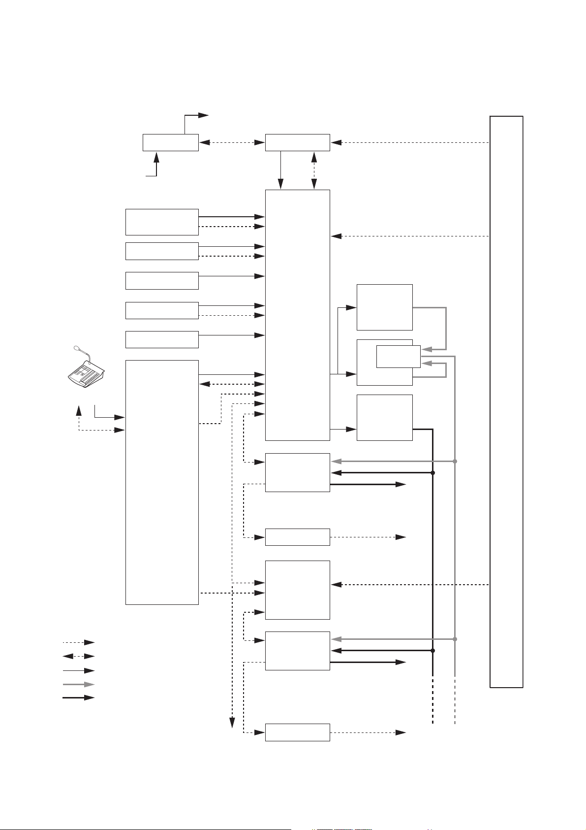
2. SYSTEM SUMMARY
24 V DC (supplied to rack internal components)
230 V AC
FS-7000RM
FS-7000PS
50 Hz
Timer-operated
sound source
CP microphone
Sound source
PBX
BGM player
ZONES 1 – 10
OUT
RF CONT
FS-7000EV
TIMER
BUSY
FLOOR ID
CP MIC
TALK SW
AUX
CALL
BUSY
BGM
FS-7000CP
RF CONT
RF ZONE
CP CONT
JP CONT
ContEV IN
PRIORF IN
BGM
Confirmation signal
Floor identifier signals 1 – 10
FS-7006PA
YA-7000
FS-7006PA
FS-7006PA
FS-7000RF
Max. 50 zones
ZONES 11 – 20
: Control line, 1-way
: Control line, 2-way
: Audio signal
: Speaker output (priority)
: Speaker output (BGM)
FS-7000JP
AT CONT
FS-7000AT
FS-7010CP
CP CONT
RF CONT
GM CONT
JP CONT
FS-7000JP
AT CONT
FS-7000AT
Automatic fire alarm system
Speaker outputs 1 – 10
Attenuator controls
1 – 10
Floor identifier signals
11 – 20
Speaker outputs
11 – 20
Attenuator controls
11 – 20
Page 8
8
3. FEATURES
• The FS-7000EV is loaded with English language messages when shipped from the factory.
• The semiconductor memory incorporated in the FS-7000EV ensures stable rebroadcast of recorded
messages.
• If speaker lines are shorted, the line protection fuse disconnects the shorted lines and a line short indication
is displayed.
• Simultaneous 2-channel broadcasts can be made of BGM (background music) and announcement
broadcasts (emergency and priority broadcasts), allowing BGM broadcasts to continue in zones not selected
for announcement broadcasts, even when announcements are being made.
• Up to 4 remote microphones can be connected.
• Up to 200 speaker lines can be controlled.
• Time signals can be simultaneously broadcast over all zones by connecting timer-operated sound sources.
• All-zone calls can be made from a telephone set by connecting the system to a telephone exchange.
• Connection of the emergency power supply panel permits emergency broadcasts to be made even during a
power failure.
4. INSTALLATION PRECAUTIONS
• The required power voltage for this system is 230V AC. Calculate the total combined power consumption of
all equipment in the system to ensure ample power capacity. Note that the system may not work properly
due to breaker cutoff or power voltage drops when the total supply voltage is insufficient.
• About the handling of the power supply cord (FS-7000PS only):
The supplied power cord is intended for exclusive use with the FS-7000PS Power Supply Panel. Avoid using
this power cord for any other equipment than the PS-7000PS panel.
• Ensure that the rear of the component is sufficiently distant from the rear wall to facilitate maintenance
service. Speaker line protection fuses and output overcurrent fuses are located on the component rear
panel. Sufficient space must be provided between the back of the component and the rear wall surface to
change the fuses.
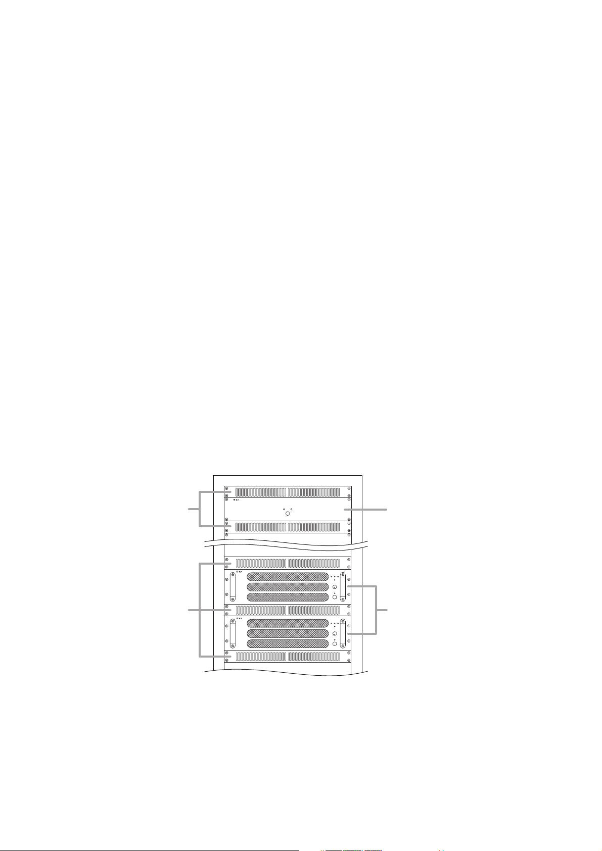
• When mounting the FS-7000PS and FS-7006PA or FS-7012PA in an equipment rack, mount a Perforated
Panel larger than 1U size* just above and below each component, as shown in the following figure.
• When mounting the FS-7006PA or FS-7012PA power amplifier in an equipment rack, keep the rear of the
amplifier at least 10 cm away from the rear wall so that its rear panel-mounted fan vent is not blocked.
• Each component is designed with robust construction. However, be sure to use reinforcement brackets
when mounting if extra strength is required.
• No rack mounting screws are supplied with the system. Use the appropriate screws for the racks used.
*1U size = 44.5 mm (standard size)
Perforated Panels
Perforated Panels
DC Power Supply Panel
FS-7000PS
Power Amplifiers
FS-7006PA/7012PA
Page 9
9
5. NOMENCLATURE AND FUNCTIONS
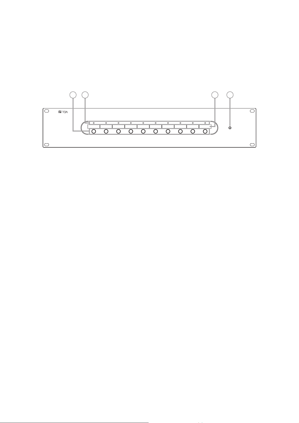
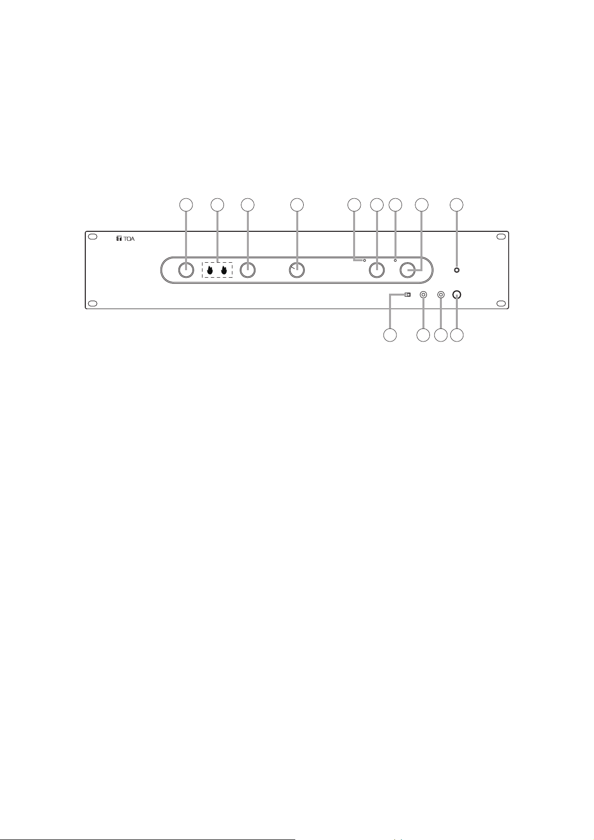
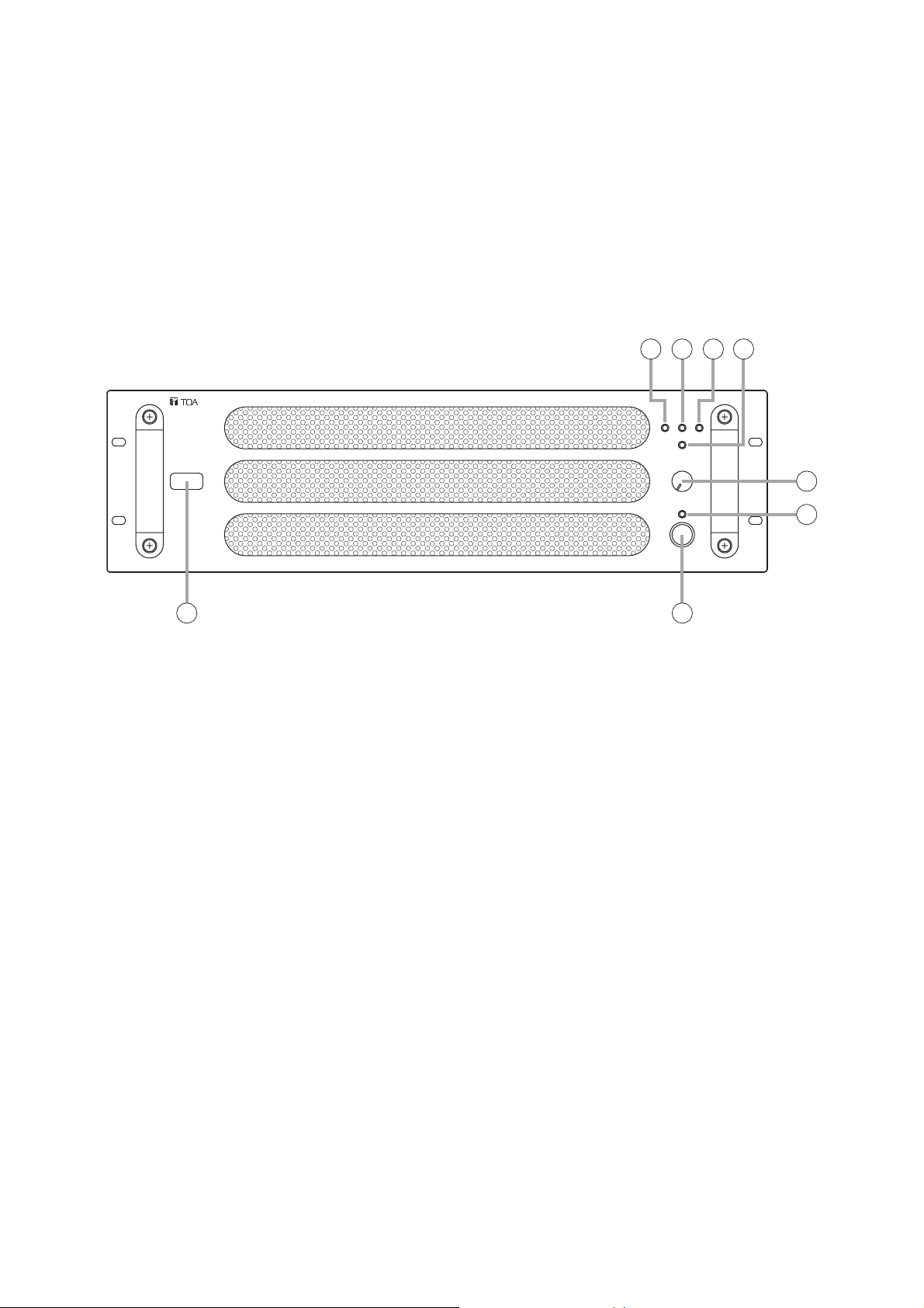
5.1. FS-7000CP Control Panel
The FS-7000CP is a standard operation panel for the FS-7000 Series Voice Evacuation Systems.
It is designed to be used in conjunction with the FS-7000JP panel, and enables individual paging calls to up to
10 zones plus all-zone calls.
The number of zones can be expanded to up to 200 zones in 10-zone units by connecting the FS-7010CP
expansion panel. Further, connection of both the FS-7000GM panel and the FS-7010CP panel permits
creation of up to 20 broadcast zone groups.
The FS-7000CP is equipped with a built-in pre-amplifier function and chime unit (ascending 4-note tone).
Audio output can be set to either a 2-channel output of background music (BGM) and priority broadcast or a 1channel output of mixed BGM and priority broadcast.
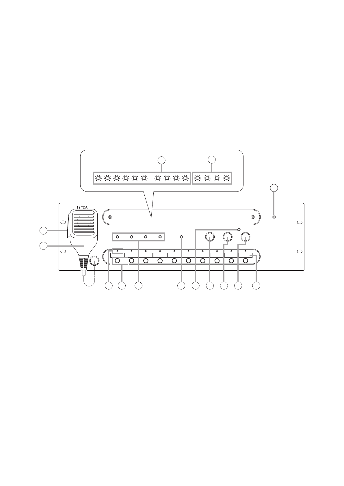
[Front]
1. Power Indicator
Lights when power is supplied and the FS7000CP is ready for operation.
2. CP Microphone
Make announcements while holding down the
Talk Switch (3). The microphone can be used only
while the FS-7000CP panel is in use or
emergency broadcasts are in progress.
3. Talk Switch
Hold down this switch to make announcements
using the microphone.
4. Volume Controls
Adjust the sound volume for each audio input.
Turning the control clockwise increases the
volume, while turning it counterclockwise
decreases the volume.
Controls are arranged from left to right as follows:
• EV
Adjusts the volume of the EV Audio Input on the
rear panel.
• TIMER
Adjusts the volume of the Timer Input on the rear
panel.
• PAGING
Adjusts the volume of the Paging Input on the rear
panel.
• RM MIC
Adjusts the volume of the RF Audio Input on the
rear panel.
• CP MIC
Adjusts the volume of the CP Microphone (2).
• CHIME
Adjust the volume of the built-in 4-tone chime.
• BGM 1 – 4
Adjusts the volume of BGM Inputs 1 – 4 on the
rear panel.
Inside of the front cover
3
2
7 9 10 11 12 136 148
4
5
1
Page 10

10
5. Tone Controls
Adjust high and low frequencies of the output.
Frequencies are accentuated when the control is
rotated clockwise, and attenuated when rotated
counterclockwise. Controls are arranged from left
to right as follows:
• PRIORITY BASS
Adjusts the low frequencies of the Priority Output
on the rear panel.
• PRIORITY TREBLE
Adjusts the high frequencies of the Priority Output
on the rear panel.
• BGM BASS
Adjusts the low frequencies of the BGM Output on
the rear panel.
• BGM TREBLE
Adjusts the high frequencies of the BGM Output
on the rear panel.
6. Zone Indicators
Light to indicate current broadcast zones.
Note
These indicators also light during emergency
broadcasts when broadcast zones are selected by
signal inputs from an automatic fire alarm system.
7. Zone Selector Keys
Press these keys to select broadcast zones. To
cancel the selection, press the keys again.
Multiple broadcast zones can be selected
simultaneously with the additional use of the FS7000GM panel.
8. Busy Status Indicators
The indicator corresponding to the component
currently in use for broadcast lights while the
system is in general-purpose broadcast mode.
Note
These indicators do not light during emergency
broadcasts.
The priorities of the indicators are: TIMER,
PAGING, RM MIC, and CP IN-USE from high to
low. (Emergency broadcasts take precedence
over all other equipment operations.)
Each indicator is arranged from left to right as
follows:
• TIMER
Remains lit during broadcasts from the component
connected to the timer input.
• PAGING
Remains lit during broadcasts from the
component connected to the paging input.
• RM MIC
Remains lit during broadcasts from the FS7000RM.
• CP IN-USE
Remains lit during broadcasts from the FS7000CP. Announcements can be made via the
CP Microphone (2).
9. Speaker Line Short Indicator
Lights when 1 or more speaker lines connected
to the FS-7000JP have shorted.
(See page 77.)
10. All-Zone Call Indicator
Lights when the All-Zone Call button (13) is
pressed to select all broadcast zones
simultaneously. (Lights continuously only while
the FS-7000CP is operating or emergency
broadcasts are being made.)
11. Chime Button
Sounds a built-in 4-tone chime. This button can
be used only while the FS-7000CP is operating.
12. Reset Button
Resets the broadcast zones selected with the
Zone Selector keys (7) or All-Zone Call button
(13). Pressing this button also terminates
general-purpose broadcasts provided from the
FS-7000CP.
13. All-Zone Call Button
Selects all broadcast zones simultaneously.
14. Broadcast Zone Fill-In Space
Write the names of zones to be selected with the
Zone Selector keys (7) in this space.
Page 11
11
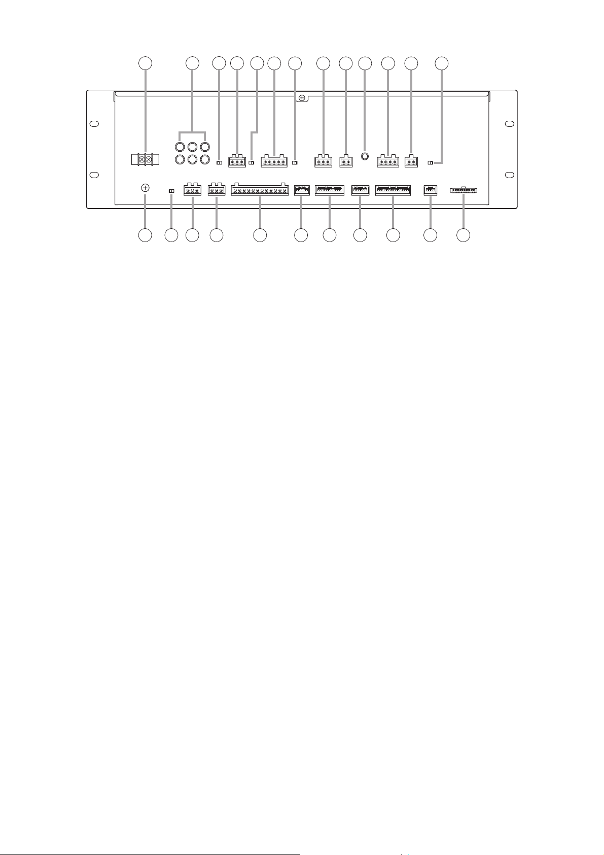
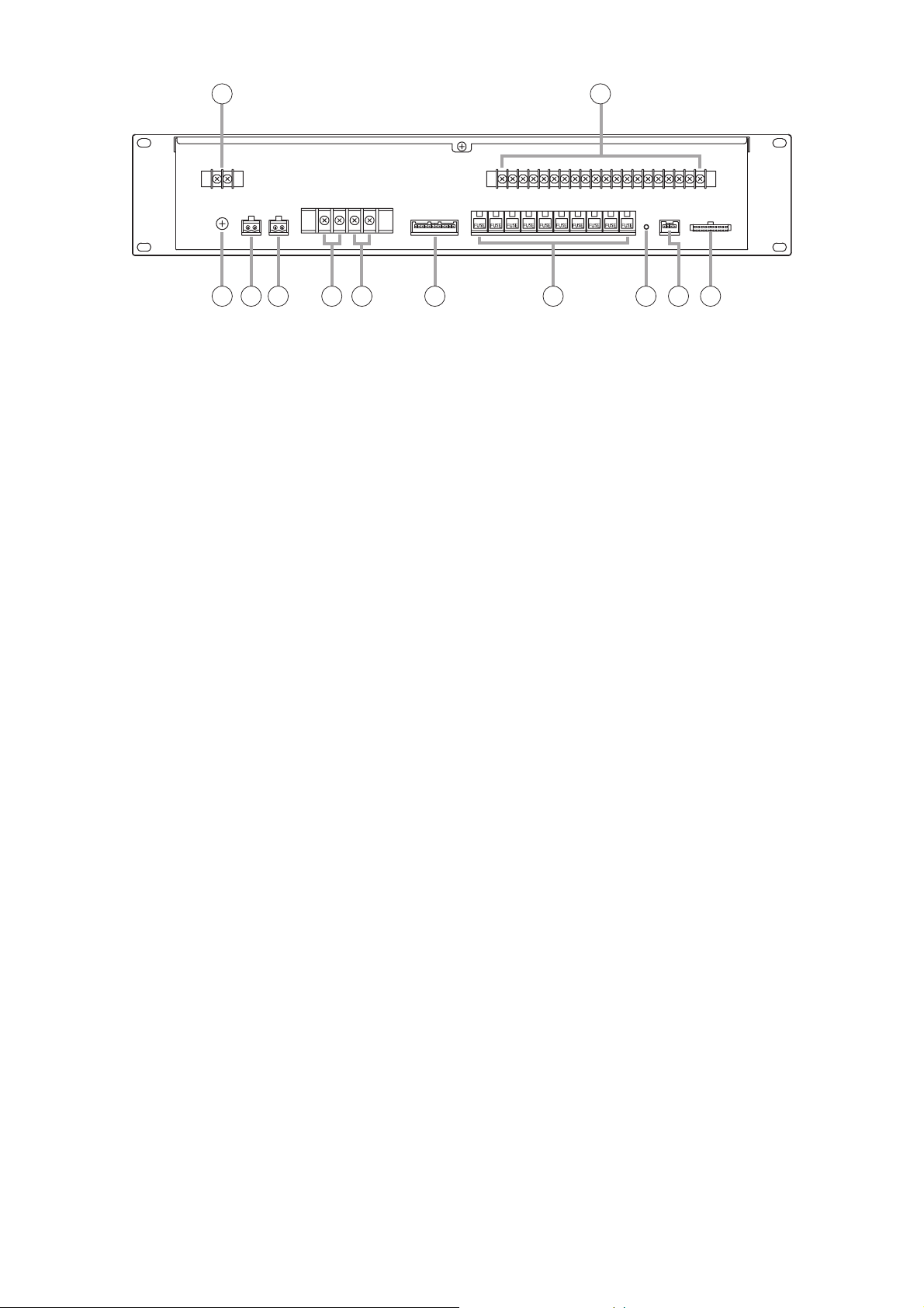
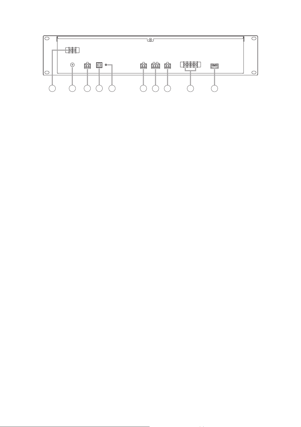
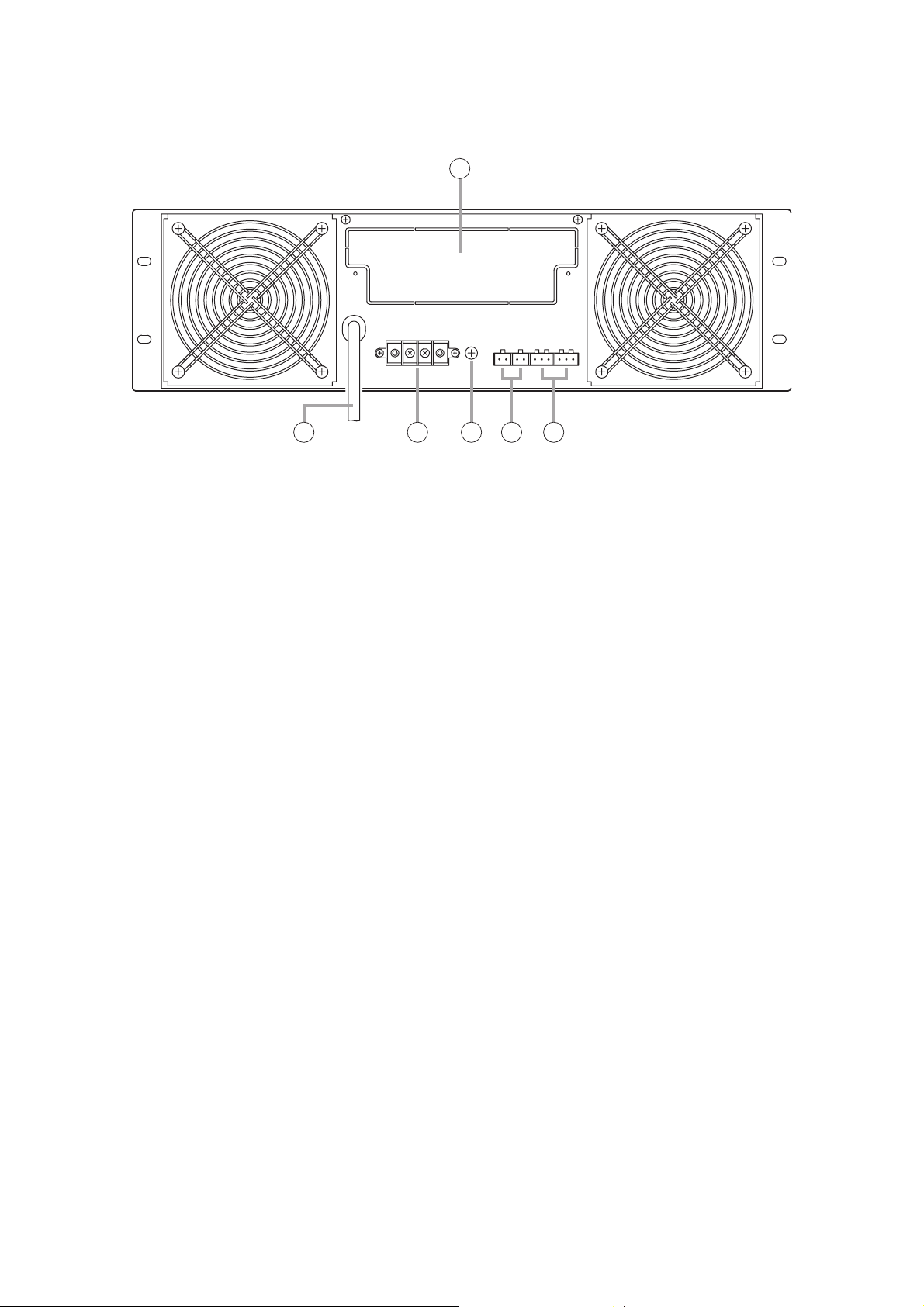
[Rear]
15. DC Power Input Terminal
Connect 24 V DC power to this terminal. Power
is supplied from the FS-7000PS.
(M3 screw terminal; barrier distance: 6.4 mm)
16. BGM Input Terminals 2,3,4
Connect background music equipment to these
terminals. When the output is set to 2-channel
broadcast, background music is supplied from
the BGM Output (30). When the output is set to
1-channel broadcast, background music is mixed
with priority broadcasts and provided from the
Priority Output (31) as well. However, activation
of the muting function* due to signal inputs other
than BGM will attenuate the BGM level.
BGM inputs 2 – 4: –20 dBV, 10 kΩ, unbalanced,
2P RCA jack
* Muting function: A function that automatically
decreases the volume of original broadcast when
another broadcast is initiated during original
broadcast, and restores the original broadcast
volume level when the other broadcast is
completed.
17. Mute Switch
Sets whether or not to attenuate the signal levels
of BGM Inputs 2 – 4 (16) when a broadcast is
made from the BGM Input 1 (18). (Default: OFF)
18. BGM Input Terminal 1
Connect background music equipment to this
terminal. When the output is set to 2-channel
broadcast, BGM is supplied from the BGM
Output (30). Setting the muting function permits
this input to take precedence over BGM Inputs 2
– 4. When the output is set to 1-channel
broadcast, background music is mixed with
priority broadcasts and provided from the Priority
Output (31) as well. However, activation of the
muting function due to signal inputs other than
BGM will attenuate the BGM level. (–60 dBV/0
dBV selectable, 600 Ω, balanced, 3P terminal
block)
19. BGM Input 1 Sensitivity Selector Switch
Sets the input sensitivity of BGM Input 1 (18) to
"–60 dBV" or "0 dBV." (Default: 0 dBV)
20. Paging Input Terminal
Connect audio and control signals from
equipment (such as telephone paging
equipment) to this terminal. Input signals to this
terminal are broadcast when the control
terminals are closed.
Audio: –60 dBV/–20 dBV selectable, 600 Ω,
balanced
Control: Open voltage: 26 V DC; short-circuit
current: under 2 mA
5P terminal block
21. Paging Input Sensitivity Selector Switch
Sets the input sensitivity of Paging Input (20) to
"–60 dBV" or "–20 dBV."
(Default: –20 dBV)
22. RF Audio Input Terminal
Used to connect the FS-7000RF. Audio signals
from the FS-7000RM are input via the FS7000RF. (0 dBV, 600 Ω, balanced, 3P terminal
block)
23. Auxiliary Input Terminal
Signals received by this terminal are mixed with
signals from the CP Microphone (2) and output
while the FS-7000CP is in operation.
(–20 dBV, 600 Ω, unbalanced, 2P terminal block)
24. Auxiliary Input Volume Control
Adjusts the sound volume of Auxiliary Input (23).
16 1715
18 19
20
26
2721 22 23 24 25
28 30 31 32 33 34 35 3629 37 38
Page 12

12
25. Timer Input Terminal
Connect audio and control signals from timeroperated equipment to this terminal. Input
signals to this terminal are broadcast with the
highest priority when the control terminals are
closed.
Audio: 0 dBV, 600 Ω, unbalanced
Control: Open voltage: 26 V DC; short-circuit
current: under 2 mA
4P terminal block
26. EV Audio Input Terminal
Used to connect the FS-7000EV. This input can
be used only while an emergency broadcast is
being made. (0 dBV, 600 Ω, unbalanced, 2P
terminal block)
27. Output Mode Selector Switch
Sets the audio output to "1-CH" (1-channel) or
"2-CH" (2-channel) broadcasts.
(Default: 2-channel broadcast)
28. Functional Earth Terminal
Connect this terminal to the functional earth
terminal of external equipment if excessive noise
is generated when the FS-7000CP is connected
to the external equipment. This could reduce
noise.
Note: This terminal is not for protective earth.
29. All-Zone Call Mode Selector Switch
Sets the mode of broadcast to be initiated with
the All-Zone Call button (13). When the FS7000AT has been connected to the system, if
this switch is set to "URGE" (general urgency)
and an all-zone call is made, a 24 V DC for
controlling attenuators is output, permitting the
call to bypass the attenuator. (Default: "NORM")
30. BGM Output Terminal
Signals from the BGM Inputs 1 – 4 (16 and 18)
are mixed and output. Connect this terminal to
the power amplifier for BGM broadcast. (0 dBV,
600 Ω, balanced, 3P terminal block)
31. Priority Output Terminal
When the Output Mode Selector Switch (27)
is set to 2-channel broadcast:
Outputs signals other than those from the BGM
Inputs 1 – 4 (16 and 18). Connect this terminal to
the power amplifier intended for priority
broadcast.
When the Output Mode Selector Switch (27)
is set to 1-channel broadcast:
Outputs signals from all audio inputs. Signals
output from sources other than BGM Inputs 1 – 4
causes these 4 BGM input signals to atttenuate.
Connect this terminal to the power amplifier. (0
dBV, 600 Ω, balanced, 3P terminal block)
32. Automatic Fire Alarm System Input Terminal
Connect this terminal to the floor identifier signal
transmitted from the automatic fire alarm system.
The identifier signal automatically selects zones
and broadcasts audio alarms to such zones.
(Open voltage: 26 V DC; short-circuit current:
under 5 mA; 12P terminal block; 10 zones +
COM + COM)
Note
This terminal is not connected when the FS7000EV is not used.
33. EV Control Terminal
Connect the FS-7000EV to this terminal.
34. RF Zone Control Terminal
Use this terminal to connect the FS-7000RF.
Data regarding broadcast zones transmitted from
the FS-7000RF is input to this terminal.
35. RF Control Terminal
Use this terminal to connect the FS-7000RF.
36. CP Control Terminal
Use this terminal to connect the FS-7010CP. All
of the FS-7010CP units that are mounted in the
system must be connected to this terminal.
37. JP Control Terminal
Connect this terminal to the FS-7000JP when the
FS-7000GM is not connected to the system.
Note
This terminal is not used when the FS-7000GM
is connected to the FS-7000CP.
38. JP/GM Control Terminal
Connect this terminal to the FS-7000JP or FS7000GM.
When the FS-7000GM is not connected to the
FS-7000CP:
Connect this terminal to the FS-7000JP in order
to control speaker line ON/OFF operations.
When the FS-7000GM is connected to the FS7000CP:
Connect this terminal to the FS-7000GM. The
Zone Selector keys (7) on the front panel
function as group selector keys.
Page 13
13
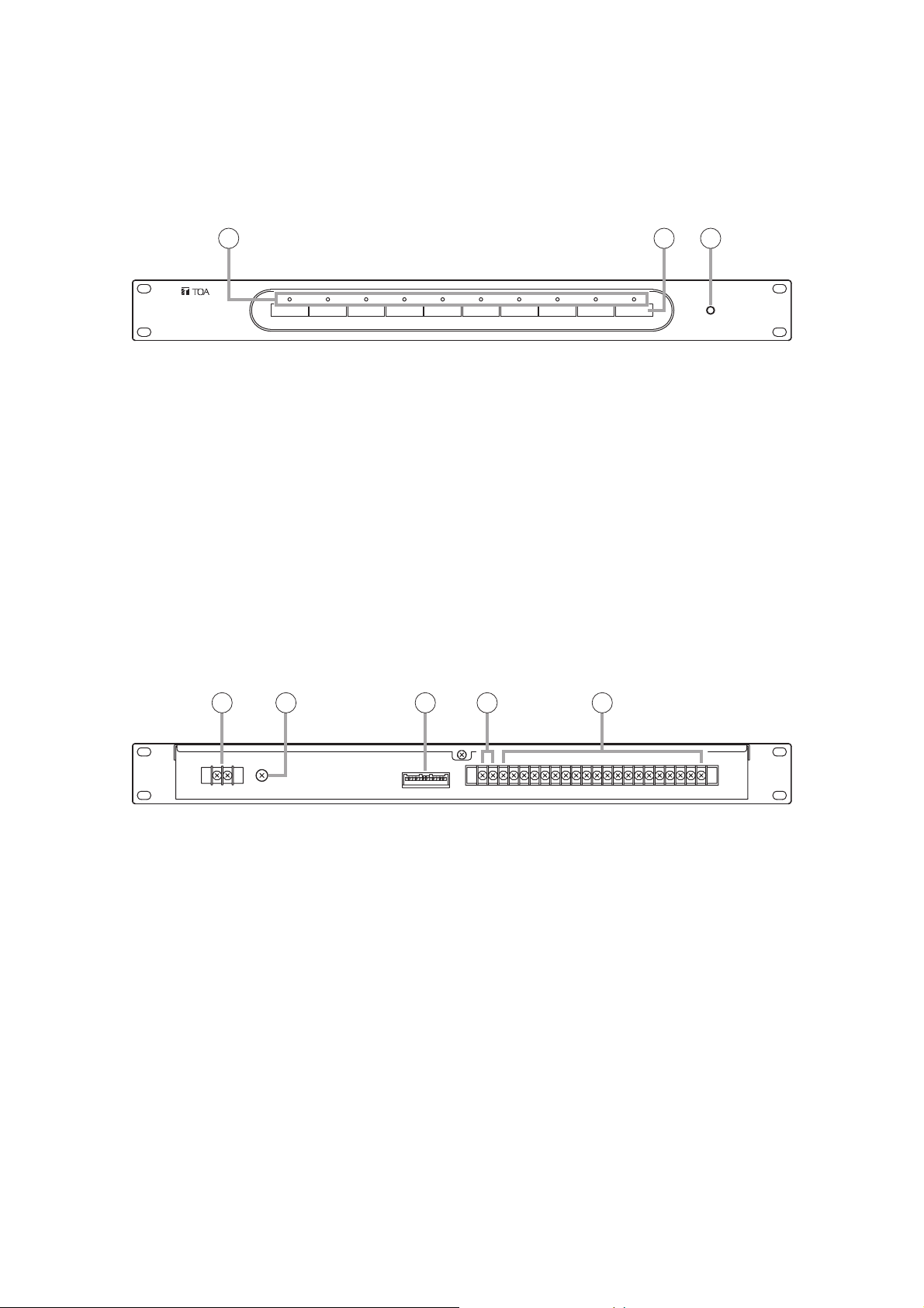
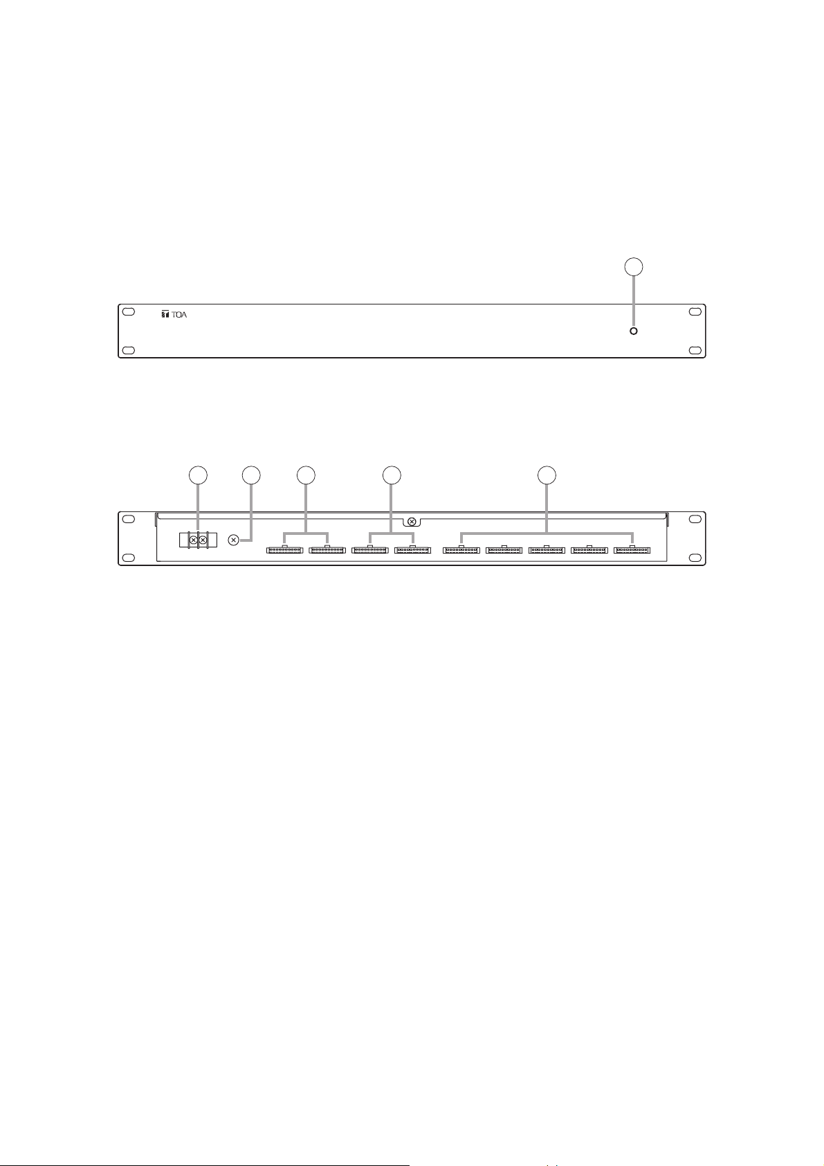
5.2. FS-7010CP Expansion Control Panel
The FS-7010CP is used to expand the broadcasting capacity of FS-7000 Series Voice Evacuation Systems.
Announcements and background music can be broadcast to up to 10 individual zones. Connecting the FS7000GM to the FS-7000CP/FS-7010CP combination permits broadcasts to be made to up to 20 zone groups.
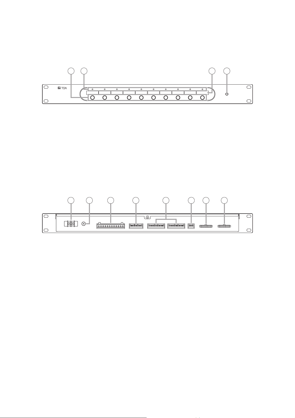
[Front]
1. Power Indicator
Lights when power is supplied and the FS7010CP is ready for operation.
2. Zone Selector Keys
Press these keys to select broadcast zones. To
cancel the selection, press the keys again.
Multiple broadcast zones can be selected
simultaneously with the additional use of the FS7000GM.
3. Zone Indicators
Light to indicate current broadcast zones.
Note
These indicators also light during emergency
broadcasts when their corresponding zones are
selected by automatic fire alarm signals.
4. Broadcast Zone Fill-In Space
Write the names of zones to be selected with the
Zone Selector keys (2) in this space.
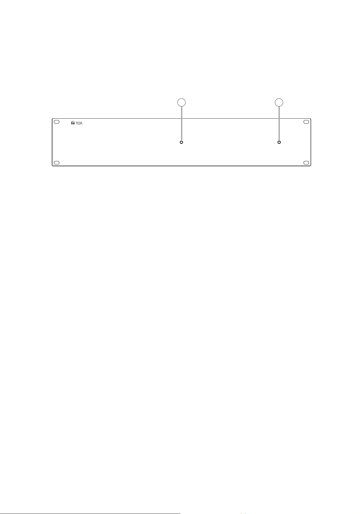
5. DC Power Input Terminal
Connect 24 V DC power to this terminal. Power is
supplied from the FS-7000PS.
(M3 screw terminal; barrier distance: 6.4 mm)
6. Functional Earth Terminal
Connect this terminal to the functional earth
terminal of external equipment if excessive noise
is generated when the external equipment is
connected to the FS-7010CP. This could reduce
noise.
Note: This terminal is not for protective earth.
7. Automatic Fire Alarm System Input Terminal
Connect this terminal to floor identifier signals
transmitted from the automatic fire alarm system.
The identifier signal designates broadcast zones
to provide audio alarm to such zones. (Open
voltage: 26 V DC; short-circuit current: under 5
mA; 12P terminal block; 10 zones + COM + COM)
Note: This terminal is not connected when the FS-
7000EV is not used.
8. RF Zone Control Terminal
Use this terminal to connect the FS-7000RF.
9. CP Control Terminal
Connect this terminal to the FS-7000CP or other
FS-7010CP units. All of the FS-7010CP units
within the system must be connected to the FS7000CP.
10. JP Control Terminal
Connect this terminal to the FS-7000JP Junction
Panel.
11. JP Zone Control Terminal
Connect this terminal to the FS-7000JP in order
to control speaker line ON/OFF operations.
12. GM Zone Control Terminal
Connect this terminal to the FS-7000GM when
the FS-7000GM is connected to the FS-7000CP.
[Rear]
2 3 4 1
6 7 85 119 10 12
Page 14
14
1. Power Indicator
Lights when power is supplied and the FS-7000JP
panel is ready for operation.
2. BGM Zone Selector Keys
Press these keys to select BGM broadcast zones.
Press the keys again to cancel the selection. (2channel broadcast)
3. Speaker Line Indicators
Indicate speaker line operating statuses as
follows:
Green: BGM broadcast in progress (2-channel
broadcast)
Orange: BGM broadcast in progress (1-channel
broadcast) or priority or emergency
broadcasts in progress
Red: Short-circuit (see page 77.)
4. Broadcast Zone Fill-In Space
Write the names of zones to be selected with the
BGM Zone Selector keys (2) in this space.
5.3. FS-7000JP Junction Panel
The FS-7000JP panel is used in conjunction with the FS-7000CP and the FS-7010CP to connect speaker
lines in FS-7000 Series Voice Evacuation Systems. It can connect up to 10 speaker lines. If speaker lines are
shorted, the line protection fuses disconnect the shorted lines, leaving broadcasts to other speaker lines
functioning intact. The FS-7000JP is equipped with BGM input and priority broadcast input, with BGM
broadcast zones selectable using the keys on the front panel. Priority broadcast zones are selected using the
FS-7000CP.
[Front]
4 12 3
Page 15
15
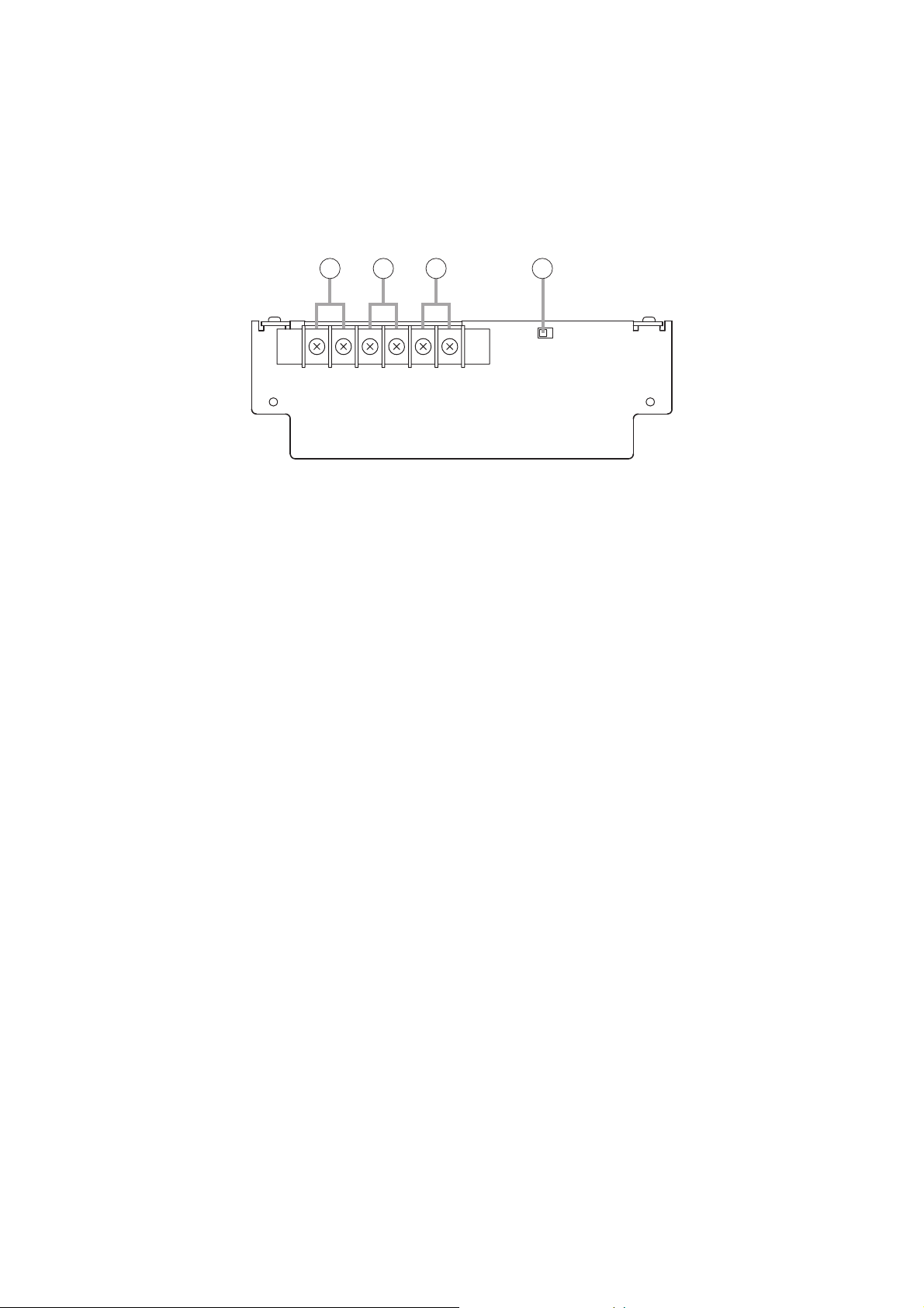
[Rear]
5. DC Power Input Terminal
Connect 24 V DC power to this terminal. Power
is supplied from the FS-7000PS.
(M3 screw terminal; barrier distance: 6.4 mm)
6. Speaker Output Terminal
Connect this terminal to speaker lines. Ten lines
can be connected.
Maximum per-line output (high impedance, 100
V line)
When the FS-7006PA amplifier is connected:
280 W
When the FS-7012PA amplifier is connected:
500 W
(M3 screw terminal; barrier distance: 6.4 mm)
7. Functional Earth Terminal
Connect this terminal to the functional earth
terminal of external equipment if excessive noise
is generated when the FS-7000JP panel is
connected to the external equipment. This could
reduce noise.
Note: This terminal is not for protective earth.
8. General Urgency/Emergency Mode Output
Terminal
Activated while a General urgency broadcast or
Emergency broadcast is being made.
(Open collector output; rated voltage: 30 V DC;
current capacity: 0.1 A; 2P terminal block)
9. Power Remote Output Terminal
Activated when a broadcast is made to any zone.
This terminal can be used for remotely
controlling the power amplifier's power supply.
(Relay output; rated voltage: 30 V DC; current
capacity: 1 A; 2P terminal block)
10. BGM Input Terminal
Connect this terminal to the power amplifier
intended for BGM broadcast.
(M4 screw terminal; barrier distance: 9 mm)
Note
Only 1 piece of FS-7006PA, FS-7012PA or YA7000 can be connected to this terminal. Never
connect 2 or more units to this terminal, as the
excessive load could cause the amplifier to fail.
11. Priority Input Terminal
Connect this terminal to the output of the power
amplifier intended for priority broadcast.
(M4 screw terminal; barrier distance: 9 mm)
Note
Only 1 piece of FS-7006PA, FS-7012PA or YA7000 can be connected to this terminal. Never
connect 2 or more units to this terminal, as the
excessive load could cause the amplifier to fail.
12. Attenuator Connection Terminal
Connect this terminal to the FS-7000AT.
13. Speaker Line Protection Fuses
Disconnect shorted speaker lines to prevent
adverse effects on other speaker lines.
Note
Install the fuse having the correct capacity for all
the connected speakers.
14. Reset Switch
Pressing this switch after removing the cause of
a speaker line short and replacing the blown
Speaker Line Protection Fuse (13) restores
broadcasts to that speaker line.
15. JP Control Terminal
Connect this terminal to the FS-7000CP and FS7010CP.
16. JP Zone Control Terminal
Connect this terminal to the FS-7000CP and FS7010CP to select speaker lines during priority
broadcasts.
5
6
7 8
119 10 12 13 14 15 16
Page 16
16
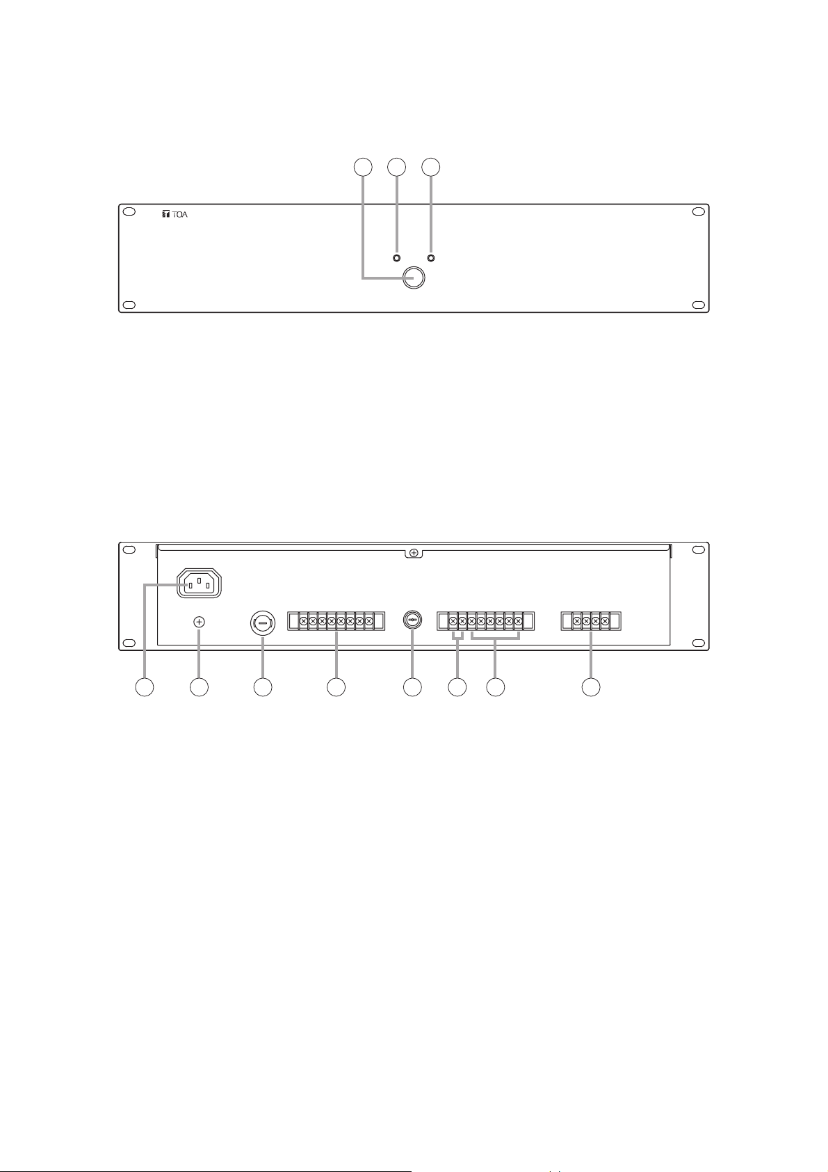
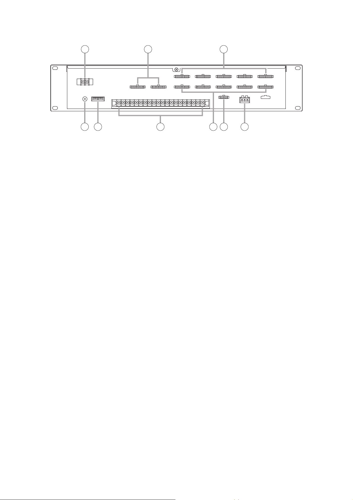
5.4. FS-7000PS DC Power Supply Panel
The FS-7000PS supplies 24 V DC power to each component used in FS-7000 Series Voice Evacuation
Systems. Connecting the DS-029B provides a power supply for emergency broadcasts even during power
failures.
[Front]
1. AC Power Switch
AC power is turned on and off with each press of
this switch.
2. AC Power Indicator
Lights when AC power is supplied and the FS7000PS is ready for operation on AC power.
3. DC Power Indicator
Lights when DC power is supplied and the FS7000PS is ready for operation on DC power.
4. AC Power Inlet
Connect the supplied power cord to this inlet.
5. Functional Earth Terminal
Connect this terminal to the functional earth
terminal of external equipment if excessive noise
is generated when the external equipment is
connected to the FS-7000PS. This could reduce
noise.
Note: This terminal is not for protective earth.
6. AC Fuse
Protects the unit against output overcurrent when
the unit is operated on AC power. When replacing
the fuse, use the specified type.
7. 24 V DC Output Terminal
Connect this terminal to the 24 V DC input of each
system component.
M3 screw terminal; barrier distance: 6.4 mm;
current capacity: 5 A (total).
8. DC Fuse
Protects the unit against output overcurrent when
the unit is operated on DC power. When
replacing the fuse, use the specified type.
9. Grounding Terminal
Disconnects a 24 V DC output ground from a
frame ground. (Default: Shorted between F.G
and S.G)
(M3 screw terminal; barrier distance: 6.4 mm)
10. Emergency Power Connection Terminal
Connect this terminal to the DS-029B to enable
emergency broadcasts even during power
failures.
(M3 screw terminal; barrier distance: 6.4 mm)
11. Emergency Power Control Terminal
Activates an emergency power supply unit to
enable emergency broadcasts during power
failures. Connect this terminal to the FS-7000EV.
(M3 screw terminal; barrier distance: 6.4 mm)
[Rear]
1 2 3
6 7 85 119 104
Page 17
17
5.5. FS-7000AT Attenuator Control Panel
The FS-7000AT is used in conjunction with FS-7000 Series Voice Evacuation Systems to control 4-wire
system attenuators. Up to 10 zones can be attenuator-controlled. When general urgency or emergency
broadcasts are made, the FS-7000AT provides 24 V DC power to allow such broadcasts to bypass the
attenuators. The output status of each line can be monitored by the indicators on the front panel.
[Front]
[Rear]
1. Power Indicator
Lights when power is supplied and the FS-7000AT
is ready for operation.
2. Attenuator Line Indicators
Light when 24 V DC for bypassing the attenuators
are being supplied, and extinguish when the
overcurrent protection circuit is triggered due to
line shorts or other failures, or when the power
supply is cut off.
3. Broadcast Zone Fill-In Space
Write the names of the corresponding broadcast
zones in this space.
4. DC Power Input Terminal
Connect this terminal to 24 V DC power to be
used for internal circuits. Power is supplied from
the FS-7000PS.
(M3 screw terminal; barrier distance: 6.4 mm)
5. Functional Earth Terminal
Connect this terminal to the functional earth
terminal of external equipment if excessive noise
is generated when the external equipment is
connected to the FS-7000AT. This could reduce
noise.
Note: This terminal is not for protective earth.
6. AT Control Terminal
Connect this terminal to the FS-7000JP to control
ON/OFF operations of the Attenuator Control
Output (8).
7. ATT DC Power Input Terminal
Connect this terminal to 24 V DC power used for
attenuator control to be output from the Attenuator
Control Output Terminals 1 – 10 (8).
(M3 screw terminal; barrier distance: 6.4 mm)
8. ATT Control Output Terminals
Provide 24 V DC output for bypassing the
attenuators during general urgency or emergency
broadcasts.
[M3 screw terminal; barrier distance: 6.4 mm;
maximum current capacity: 5 A (total of 10
lines)/0.75 A (per line)]
2 3 1
6 7 854
Page 18
18
5.6. FS-7000EV Voice Evacuation Panel
The FS-7000EV is an emergency broadcast operation panel for FS-7000 Series Voice Evacuation Systems.
This panel is not required if the system is to be used solely for general-purpose public address applications. It
is possible to start and reset emergency broadcasts through manual operation. The FS-7000EV has a built-in
voice alarm device that can make both evacuation and false-alarm announcements. Not only are evacuation
announcements automatically broadcast when the system receives a fire instruction signal from the connected
automatic fire alarm system, they can also be initiated using the Evacuation Announcement button on the front
panel. False alarm announcements can be initiated using the False Alarm Announcement button on the front
panel. Evacuation and false alarm announcement messages can also be recorded using the appropriate
buttons on the front of the panel, in which case the recorded message can be confirmed by listening with
headphones.
[Front]
1. Power Indicator
Lights when power is supplied and the FS7000EV is ready for operation.
2. Emergency Reset Button
When it is confirmed that a fire has been
extinguished or other emergency situations have
returned to normal, press this button to terminate
emergency broadcasts after resetting the
connected automatic fire alarm system.
3. Fire Indicator
Indicates that an emergency broadcast is in
progress. This indicator lights when a fire
detection signal is transmitted from the automatic
fire alarm system or when the Emergency
Activation button (4) is pressed.
4. Emergency Activation Button
Press this button to manually initiate emergency
broadcasts after the occurrence of fire has been
confirmed.
5. Mode Selector Switch
Selects the operation mode of the FS-7000EV unit
to be used as a sound source for evacuation and
false alarm announcements. Set the mode to
"NORMAL" in general use. No voice alarm is
output when the mode is set to "MONITOR" or
"RECORD."
Functions of the 3 switch positions are as follows:
NORMAL: Select this mode in general use. Voice
alarms are provided at the time of
emergency broadcast.
MONITOR: Allows the operator to listen to
messages recorded on a sound
source.
RECORD: Records evacuation and false alarm
announcements on a sound source.
(Default: NORMAL)
6. Evacuation Announcement Indicator
Lights or flashes when an evacuation
announcement is played back or recorded.
7. Evacuation Announcement Button
Press this button to play back or record
evacuation announcements.
8. False Alarm Announcement Indicator
Lights or flashes when a false alarm
announcement is played back or recorded.
9. False Alarm Announcement Button
Press this button to play back or record false
alarm announcements.
10. Input Sensitivity Setting Switch
Sets the input sensitivity of Recording Input (11).
Select the sensitivity depending on the type of
connected component.
(Default: –20 dBV)
11. Recording Input Terminal
Used for recording voice alarm messages.
(–60 dBV/2.2 kΩ or –20 dBV/10 kΩ selectable,
unbalanced, mini-jack)
12. Headphone Terminal
Connect headphones to this terminal to listen to
recorded messages for confirmation. Recorded
contents are output regardless of the settings of
the Mode Selector switch.
(0 dBV, 100 Ω, unbalanced, mini-jack)
13. Headphone Volume Control
Adjusts the volume of headphones.
2 3 4 7 8 9
165
10 11 12 13
Page 19
19
[Rear]
14. DC Power Input Terminal
Connect this terminal to 24 V DC power. Power
is supplied from the FS-7000PS Power Supply
Panel.
(M3 screw terminal; barrier distance: 6.4 mm)
15. Functional Earth Terminal
Connect this terminal to the functional earth
terminal of external equipment if excessive noise
is generated when the external equipment is
connected to the FS-7000EV. This could reduce
noise.
Note: This terminal is not for protective earth.
16. EV Audio Output Terminal
Connect this terminal to the FS-7000CP for
broadcasting evacuation announcements and
other voice alarms. Such alarms are output only
when the Mode Selector switch (5) is set to the
Normal position.
(0 dBV, 600 Ω, unbalanced, 2P terminal block)
17. USB Terminal
Connect this terminal to a PC or other equipment
using the USB cable. With this connection the
built-in sound source can be rewritten using
dedicated software.
18. USB Communication Indicator
Lights or flashes during USB communications.
19. Emergency ON Output Terminal
Activated during emergency broadcasts. This
terminal is connected to the FS-7006PA or FS7012PA amplifier to disable PA attenuators while
emergency announcements are being made.
(Relay output; rated voltage: 30 V DC; current
capacity: 1 A; 2P terminal block)
20. Emergency Control Contact Output Terminal
There are an output that is activated and an
output that is deactivated during emergency
announcements.
(Relay output; rated voltage: 30 V DC; current
capacity: 1 A; 3P terminal block)
21. Automatic Fire Alarm System Confirmation
Signal Input Terminal
Connect this terminal to a confirmation signal
(fire confirmation signal) from the automatic fire
alarm system. Evacuation announcements are
broadcast if they have not yet been initiated
when this signal is received.
[Open voltage: 24 V DC; short-circuit current: 6
mA, 2P terminal block (1 channel + COM)]
22. Emergency Power Control Terminal
Activates an emergency power supply unit
connected to the FS-7000PS in order to enable
emergency broadcasts during power failures.
Connect this terminal to the FS-7000PS.
Control input: Rated voltage: 24 V DC; current
capacity: 100 mA
Starting output: Open collector output; rated
voltage: 30 V DC; current capacity: 100 mA
(M3 screw terminal; barrier distance: 6.4 mm)
23. EV Control Terminal
Connect this terminal to the FS-7000CP Control
Panel.
14
15 16 18 1917
21 22 23
20
Page 20
20
5.7. FS-7000GM Group Matrix Panel
The FS-7000GM panel is used in conjunction with FS-7000 Series Voice Evacuation Systems to make group
broadcasts. The FS-7000GM connects to the FS-7000CP and FS-7000RF and enables group broadcasts by
selecting multiple speaker lines simultaneously via the zone selector keys on the FS-7000CP or FS-7000RM.
Up to 20 groups and 50 speaker lines can be made available per unit, which can be expanded to 20 groups
and 200 speaker lines by connecting 4 units.
[Front]
[Rear]
1. Power Indicator
Lights when power is supplied and the FS7000GM is ready for operation.
2. DC Power Input Terminal
Connect this terminal to 24 V DC power supply.
Power is supplied from the FS-7000PS.
(M3 screw terminal; barrier distance: 6.4 mm)
3. Functional Earth Terminal
Connect this terminal to the functional earth
terminal of external equipment if excessive noise
is generated when the external equipment is
connected to the FS-7000GM. This could reduce
noise.
Note: This terminal is not for protective earth.
4. GM Group Control Output Terminals
Used to increase the number of broadcast zones
that can be selected with a single group key by
connecting multiple FS-7000GM units. Connect
these terminals to other FS-7000GM unit.
5. GM Group Control Input Terminals
Use these terminals to change the zone selector
keys on the FS-7000CP into group selector keys
by connecting the FS-7000CP. These terminals
are also used to enable zone group selection from
the FS-7000RM by connecting the FS-7000RF. To
increase the number of zones that can be
selected simultaneously, connect these terminals
to other FS-7000GM's GM Group Control Output
Terminals (4).
6. GM Zone Control Terminals
Connect these terminals to the FS-7010CP and
FS-7000RF.
1
2 3 4 5 6
Page 21
21
5.8. FS-7000RF Remote Microphone Interface Panel
The FS-7000RF is used to connect the FS-7000RM to FS-7000 Series Voice Evacuation Systems. Up to 4
FS-7000RM units can be connected using the FS-7000RF. It is possible to control 50 speaker lines as well as
all-zone calls. Connection of the FS-7000GM enables broadcasts to be made to up to 20 zone groups.
[Front]
1. Power Indicator
Lights when power is supplied and the FS7000RF is ready for operation.
2. Fault Indicator
Lights if any failure is detected in communications
with the FS-7000RM and flashes if any failure
occurs on the FS-7000RF itself. (See page 77.)
2 1
Page 22
22
[Rear]
3. DC Power Input Terminal
Connect this terminal to 24 V DC power supply.
Power is supplied from the FS-7000PS.
(M3 screw terminal; barrier distance: 6.4 mm)
4. GM Group Control Terminals
Connect these terminals to the FS-7000GM.
Output is provided when zones are selected using
the FS-7000RM's zone selector keys programmed
to function as group selector keys.
5. GM Zone Control Terminals
Connect these terminals to the FS-7000GM.
Broadcast zones included in the group selected
via the FS-7000RM's keys designated as group
selector keys are individually input by the FS7000GM.
6. Functional Earth Terminal
Connect this terminal to the functional earth
terminal of external equipment if excessive noise
is generated when the external equipment is
connected to the FS-7000RF. This could reduce
noise.
Note: This terminal is not for protective earth.
7. Function Switch
This switch performs the following settings:
• FS-7000RM all-zone call mode (SW #1)
Sets the mode of broadcast selected with the FS7000RM's all-zone call key to Normal or Urgency.
• Number of FS-7000RM units (SW #2 and #3)
Sets the number of FS-7000RM units to 1 through
4.
• Number of system's broadcast zones (SW
#4~#6)
Sets the number of zones to 10 through 50 in 10zone units.
• Priorities among FS-7000RM units (SW #7 and
#8)
Sets priorities among the FS-7000RM units to
"None," "Last-In-First-Out," "First-In-First-Out," or
"Individual."
(Default: "Normal," "1," "10 zones," and "Last-InFirst-Out")
8. FS-7000RM Link Terminals
The following terminals are available for
connection of the FS-7000RM:
• AUDIO
Connects the audio line from the FS-7000RM.
• DC 24 V
Supplies 24 V DC power to the FS-7000RM.
• BUS
Communicates data with the FS-7000RM.
(M3.5 screw terminal; barrier distance: 7.2 mm)
9. RF Zone Control Terminals
Connect these terminals to the FS-7000CP
and/or FS-7010CP. Data of zones selected via
the FS-7000RM is output from these terminals.
10. RF Control Terminal
Connect this terminal to the FS-7000CP
11. RF Audio Output Terminal
Connect this terminal to the FS-7000CP. Audio
signals from the FS-7000RM are output.
3 4 5
6 7 8 9 10 11
Page 23
23
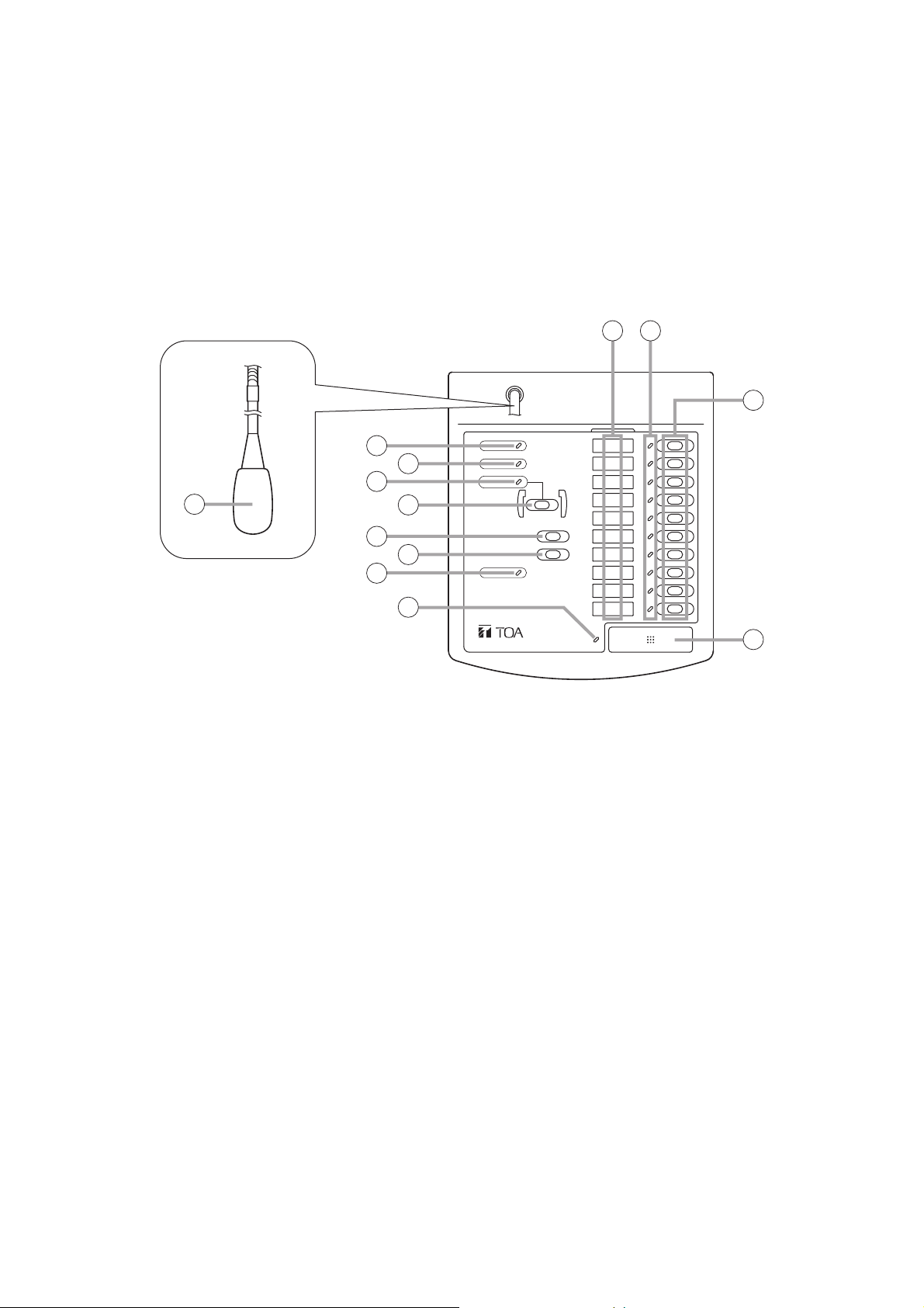
5.9. FS-7000RM Remote Microphone
The FS-7000RM Remote Microphone is used solely for general-purpose public address applications in FS7000 Series Voice Evacuation Systems. It enables broadcasting to up to 10 individual zones, as well as allzone calls. One FS-7000RF panel is required in order to connect the FS-7000RM to the system. Up to 4 FS7000RM units can be connected. Pressing the FS-7000RM's chime key causes the FS-7000CP's built-in 4tone chime to sound. Connection of 4 FS-7010RMs enables broadcasts to 50 individual zones as well as allzone calls (expandable by 10 lines per FS-7010RM). Further, up to 20 broadcast zone groups can be created
by connecting the FS-7000RF to an FS-7000GM Group Matrix Panel.
Tip
Connection of 6 FS-7010RM Remote Microphone Extension units enables broadcasting to 50 individual zones
and 20 zone groups, as well as all-zone calls.
[Top]
1. Power Indicator
Lights when power is supplied and the
FS-7000RM is ready for operation.
2. Fault Indicator
Lights when any failure is detected in
communications with the FS-7000RF or when any
failure occurs on the FS-7000RM itself.
(See page 77.)
3. All-Zone Call Indicator
Remains lit while an all-zone call is broadcast from
the FS-7000RM. (Lights only when calls are made
from this FS-7000RM.)
4. All-Zone Call Key
Selects all broadcast zones simultaneously.
5. Chime Key
Sounds a 4-tone chime built inside the FS7000CP.
6. Broadcast Reset Key
Resets broadcast zones selected via the All-Zone
Call key (4) or Zone Selector keys (11),
terminating broadcasts from the FS-7000RM.
7. Busy Indicator
Lights green when a broadcast is made from this
FS-7000RM, and lights orange when a broadcast
is made from other equipment.
8. Talk Key Indicator
Lights when a microphone announcement is made
using the Talk key (12).
9. Zone Identification Card
Write the names of the broadcast zones on this
card and insert it into the card receptacle from
top.
Note
Since this card is not supplied with the FS7000RM, prepare it according to the instructions
given on page 91.
10. Zone Selection Indicators
Light when the corresponding Zone Selector
keys (11) are pressed. (Light only when the FS7000RM's keys are used.)
11. Zone Selector Keys
Select broadcast zones. Connection of the FS7000RF to the FS-7000GM permits simultaneous
selection of multiple broadcast zones.
12. Talk Key
Microphone announcements can be made only
while this key is pressed.
Tip
Key operation can be changed to allow
microphone announcements to alternate
between ON and OFF each time this key is
pressed. (See page 75.)
13. Microphone
1
3
13
5
7
9 10
11
2
4
6
8
12
Page 24
24
[Right Side] [Rear]
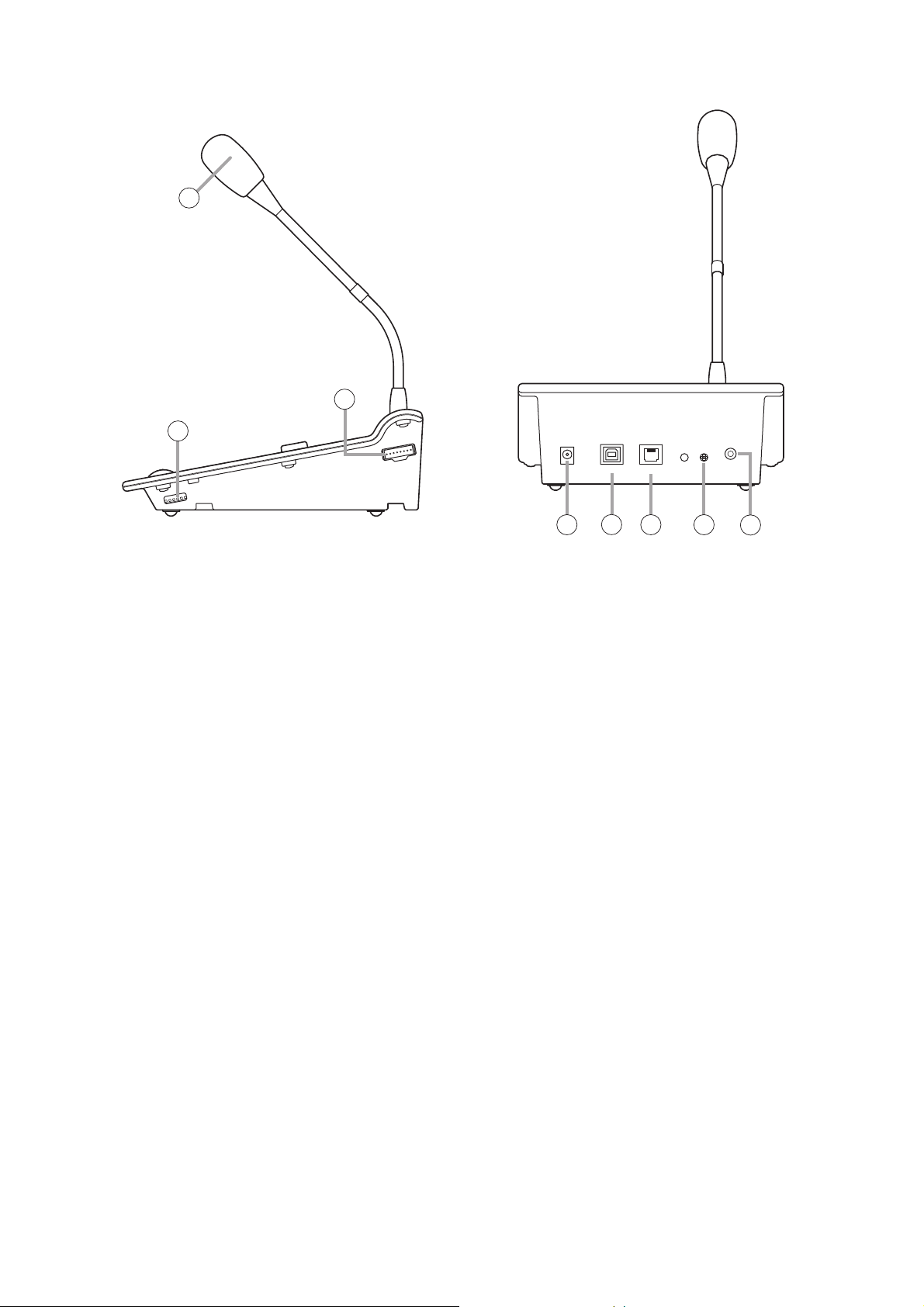
14. Setting Switch
Performs the following settings:
• Data communications address (0 – 3)
• Number of group keys (0, 10, or 20)
• Microphone compressor (ON/OFF)
[Default settings]
Data communications address: 0
Number of group keys: 0
Microphone compressor: ON
15. FS-7010RM Connection Terminal
Connect the FS-7010RM to this terminal to
increase the number of zone selector keys.
16. DC Power Supply Input Terminal
Connect this terminal to an AC adapter.
17. USB Terminal
Not used.
18. FS-7000RF Link Terminal
Connect this terminal to the FS-7000RF.
19. Microphone Volume Control
Adjusts the volume of the Microphone (13) and
External Microphone (20).
20. External Microphone Input
Connect this terminal to an external microphone.
(–40 dBV, 2.2 kΩ, unbalanced, mini-jack,
w/phantom power supply)
13
15
14
16 18 1917
20
Page 25
25
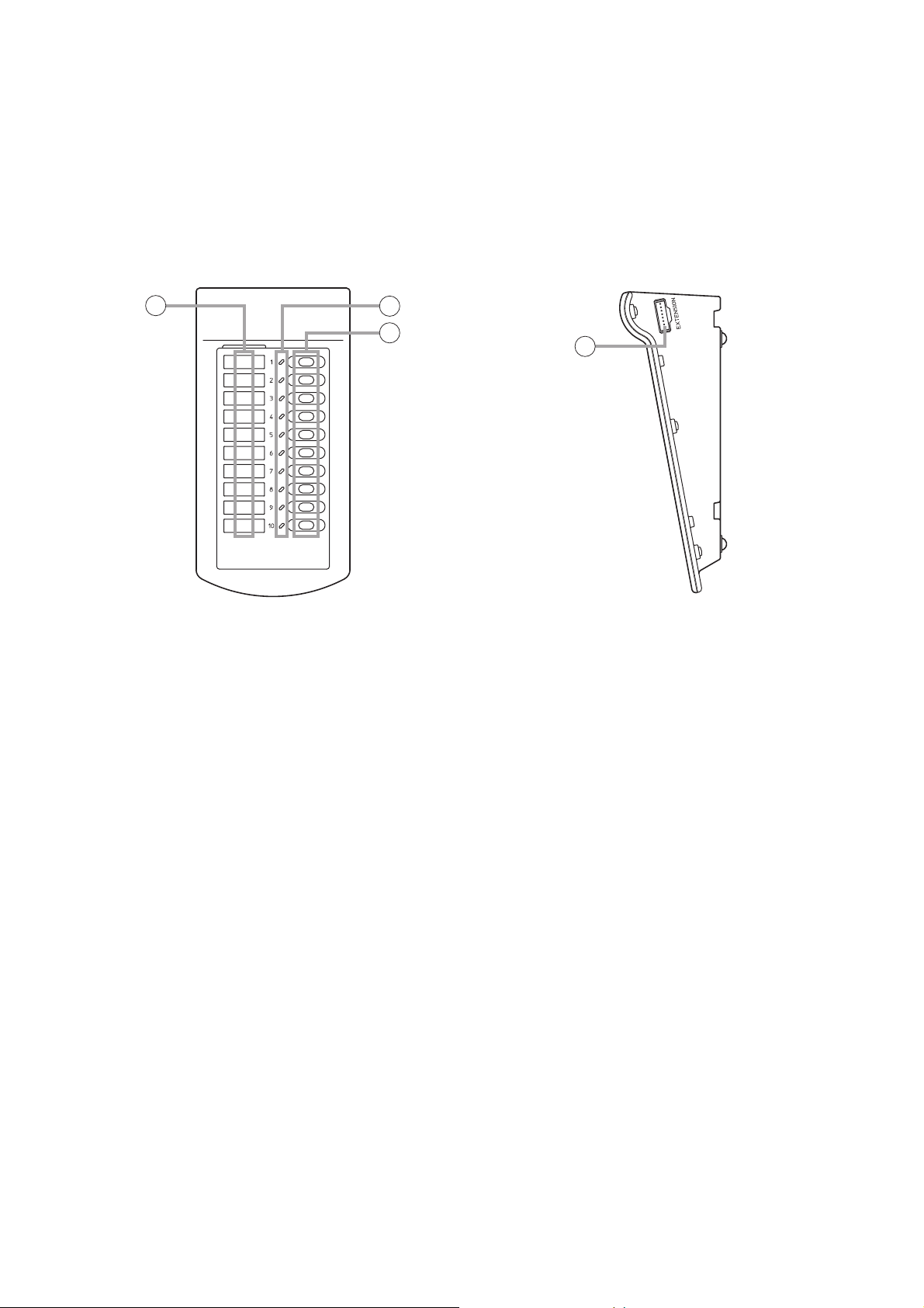
5.10. FS-7010RM Remote Microphone Extension
The FS-7010RM is an extension unit for the FS-7000RM to be used in FS-7000 Series Voice Evacuation
Systems. Ten zones can be expanded per FS-7010RM. Up to 6 FS-7010RM units can be connected to the
FS-7000RM.
[Top] [Right Side]
1. Zone Identification Card
Write the names of the broadcast zones on this
card and insert them it the card receptacle from
top.
Note
Since this card is not supplied with the FS7010RM, prepare it according to the instructions
given on page 91.
2. Zone Selection Indicators
Light when the corresponding Zone Selector keys
(3) are pressed. (Only when zones are selected
from the FS-7010RM.)
3. Zone Selector Keys
Select broadcast zones.
4. RM Connection Terminals (located on both
sides)
Connect these terminals to the FS-7000RM and/or
FS-7010RM.
1
2
3
4
Page 26
26
1. Power Switch
Press this switch to turn on the power. To turn off
the power, press this switch again.
2. Power Indicator
Lights when power is supplied and the FS7006PA/7012PA is ready for operation.
3. Volume Control
Adjusts the input signal level. This volume control
cannot be used while the Bypass Indicator (8)
continuously lights.
4. Fill-In Space
Write uses of the main and standby amplifiers in
this space.
5. Fault Indicator
Lights when an output muting function* is
operated or when a failure is detected.
If the YA-7000 is used, this indicator lights when
the YA-7000 detects a failure and the power
amplifier is switched over to a standby amplifier.
(See page 77.)
* This function prevents noise from being
generated when power is switched on and off.
6. Signal Indicator
Lights when a signal that exceeds a level 24 dB
below the rated output is sent to the Speaker Output
(11) on the rear panel.
7. Peak Indicator
Lights when a signal that exceeds a level of 3 dB
below the rated output is sent to Speaker Output (11)
on the rear panel.
8. Bypass Indicator
Lights when the Volume Bypass Control Input (13)
on the rear panel is enabled and indicates that the
Volume Control (3) has been bypassed and
disabled.
5.11. FS-7006PA/7012PA Power Amplifiers
These power amplifiers are used in conjunction with FS-7000 Series Voice Evacuation Systems. The FS7006PA's output is rated at 600 W and the FS-7012PA is rated to deliver 1,200 W. By mounting the YA-7000
module in a power amplifier and connecting a standby amplifier to it, the power amplifier can be automatically
switched over to the standby amplifier if the power amplifier fails. When initiating emergency broadcasts, the
volume control on the front panel is bypassed by closing the Volume Bypass Control terminals on the rear
panel, allowing broadcasts of emergency message at maximum volume.
[Front]
Figure shows the FS-7012PA.
7
65
8
3
2
4
1
Page 27
27
[Rear]
Figure shows the FS-7012PA.
9. YA-7000 Receptacle
Mount an optional YA-7000 module from this
receptacle. (See page 76.)
Note
Use of the YA-7000 permits the main amplifier to
be switched over to a standby amplifier if the
main amplifier fails.
10. Power Cord
Connect this cord to the wall AC outlet (230 V
AC, 50 Hz).
11. Speaker Output Terminal (with cover)
This high-impedance, 100 V line output is
connected to the FS-7000JP.
Note
Connect this terminal to the YA-7000 when the
YA-7000 has been mounted.
• FS-7006PA
M4 screw terminal; barrier distance: 9 mm; load
impedance: 16.7 Ω
• FS-7012PA
M4 screw terminal; barrier distance: 9 mm; load
impedance: 8.3 Ω
Note
Never connect this terminal to the speaker output
terminal of other FS-7006PA or FS-7012PA
power amplifier. Failure to follow this instruction
could lead to equipment failures.
12. Functional Earth Terminal
Connect this terminal to the functional earth
terminal of external equipment if excessive noise
is generated when the power amplifier is
connected to the external equipment. This could
reduce noise.
Note: This terminal is not for protective earth.
13.
Volume Control Bypass Control Input Terminal
Bypasses Volume Control (3) on the front panel
and allows announcements to be made at
maximum volume.
(Open voltage: under 24 V DC; short-circuit
current: under 10 mA; 2P terminal block)
14. Audio Signal Input Terminal
Connect this terminal to the FS-7000CP's Priority
Output and BGM Output.
(0 dB, 10 kΩ, balanced, 3P terminal block)
9
10 11 12 13 14
Page 28
28
5.12. YA-7000 Amplifier Auto Switching Module
The YA-7000 module is designed to be mounted in the power amplifier of FS-7000 Series Voice Evacuation
Systems. Connecting a standby amplifier to the YA-7000 module installed in the main amplifier (FS-7006PA or
FS-7012PA) permits the main amplifier to be switched over to the standby amplifier if the main amplifier fails.
[Front]
1. Speaker Output Terminal (with cover)
This high-impedance, 100V line speaker output
terminal connects to the FS-7000JP. Signals from
the Main Amplifier Input (2) are output when the
main amplifier (i.e. power amplifier in which the
YA-7000 has been mounted) is operating
correctly, and signals from the Standby Amplifier
Input (3) are output if a main amplifier failure is
detected.
(M4 screw terminal; barrier distance: 9 mm)
Note
Never connect this terminal to the speaker output
terminal of the FS-7006PA or FS-7012PA power
amplifier. Failure to follow this instruction could
lead to power amplifier failures.
2. Main Amplifier Input Terminal (with cover)
Connect the main amplifier's speaker output to
this terminal.
(M4 screw terminal; barrier distance: 9 mm)
Note
Only 1 piece of FS-7006PA or FS-7012PA can be
connected to this terminal. Never connect 2 or
more units to this terminal, as the excessive load
could cause the amplifier to fail.
3. Standby Amplifier Input Terminal (with cover)
Connect this terminal to the standby amplifier's
speaker output.
(M4 screw terminal; barrier distance: 9 mm)
Note
Only 1 piece of the FS-7006PA or FS-7012PA can
be connected to this terminal. Never connect 2 or
more units to this terminal, as the excessive load
could cause the amplifier to fail.
4. Operation Mode Selector Switch
Selects the YA-7000's operation mode. Set this
switch to the Normal position in general use.
(Default: Normal)
21 3 4
Page 29

29
* Fuses of ratings over 4 A can be used only when the
FS-7012PA is connected.
6. CONNECTIONS
6.1. Basic System Configuration
The basic system consists of the FS-7000CP, FS-7000JP, FS-7000PS, and FS-7006PA or FS-7012PA. This
basic configuration allows 1-channel/10-zone general-purpose broadcasts to be made. To configure
scheduled (timer-controlled) broadcasts, telephone paging, or BGM broadcasts other than announcements
using the CP microphone, refer to the specific connection instructions for the relevant pieces of equipment.
Connection examples in this chapter show the FS-7012PA being used as the power amplifier, but the same
wiring instructions also apply to the FS-7006PA.
[System Operation]
• Ten different broadcast zones can be selected individually or simultaneously.
• Broadcasts can be either announcements (made using the CP microphone installed on the FS-7000CP
Control Panel) or background music (BGM).
• The broadcast zones to be used are selected at the FS-7000CP.
• Announcements made using the CP microphone to zones where BGM broadcasts are in progress will be
audible over the BGM in those zones.
[Notes]
• Only 1 FS-7006PA or FS-7012PA unit can be connected to the FS-7000JP's Priority Input. Never connect 2
or more units to this terminal, as the excessive load could cause the amplifier to fail.
• The FS-7000JP's maximum output per speaker line varies depending on the connected power amplifiers.
Maximum power output is 500 W when the FS-7012PA is connected, and 280 W when the FS-7006PA is
connected. If the load capacity exceeds the maximum power output, divide speaker lines into 2 or more
lines.
• A 0.5A fuse is preinstalled by the factory for speaker line protection.
Depending on the total wattage of all the connected speakers on a line, replace the fuse with one having the
correct rating, referring to the following table:
WARNING
The TERMINALS marked with the symbol are HAZARDOUS LIVE.
The external wiring to these terminals requires installation by an INSTRUCTED PERSON.
[Settings]
Set the FS-7000CP's output mode selector switch to "1-CH."
Total Wattage per Speaker Line
Up to 24
25 – 40
41 – 80
81 – 120
121 – 160
161 – 200
201 – 240
241 – 280
281 – 320
321 – 400
401 – 480
481 – 500
Fuse Rating (A)
0.3
0.5
1.0
1.5
2.0
2.5
3.0
3.5
4.0 *
5.0 *
6.0 *
6.3 *
Preinstalled by the factory
Page 30

30
[Wiring Diagram]
FS-7000PS
: Supplied cables
: Cables prepared separately
See page 64; Table for Cables.
230 V AC
FS-7000CP
DC POWER IN
FS-7000JP
DC POWER IN
PRIO OUT
DC POWER OUT
PRIORITY IN
JP CONT
SP OUT
JP ZONE/
GM GROUP CONT
Speaker lines
JP ZONE CONT
FS-7012PA
230 V AC
SP OUT
JP CONT
INPUT
Page 31

31
6.2. Zone Expansion
If more than 10 broadcast zones are required, then additional FS-7010CP and FS-7000JP panels may be
added as needed. Adding 1 each of these units will increase by 10 zones. Up to 19 each of the FS-7010CP
and FS-7000JP can be added, allowing expansion to a maximum of 200 zones. The current of the 24 V DC
power supplied from the FS-7000PS is 5 A. If the addition of the expansion panel causes the 24 V DC
capacity to exceed 5 A, then add the required number of the FS-7000PS panels and divide the power supply.
[Note]
The FS-7000PS panel must be added if the total of current consumption of 24 V DC-operated equipment
(such as the FS-7010CP and FS-7000JP) exceeds 5 A.
Page 32

32
[Wiring Diagram]
The following figure shows a configuration in which 2 each of the FS-7010CP and FS-7000JP units have been
added to the basic system.
FS-7000PS
230 V AC
FS-7000CP
FS-7010CP
FS-7010CP
DC POWER IN
DC POWER OUT
CP CONT
PRIO OUT JP CONT
CP CONT
DC POWER IN
CP CONT
JP CONT
CP CONT
: Supplied cables
: Cables prepared separately
See page 64; Table for Cables.
JP ZONE/
GM GROUP CONT
JP ZONE CONT
JP ZONE CONT
FS-7000JP
FS-7000JP
FS-7000JP
FS-7012PA
DC POWER IN
DC POWER IN
DC POWER IN
DC POWER IN
PRIORITY IN
PRIORITY IN
PRIORITY IN
JP CONT
SP OUT
JP CONT
SP OUT
JP CONT
SP OUT
JP CONT
Speaker lines
1 – 10
JP ZONE CONT
Speaker lines
11 – 20
JP ZONE CONT
Speaker lines
21 – 30
JP ZONE CONT
230 V AC
SP OUT
INPUT
Page 33

33
6.3. 24 V DC Power Supply Expansion
If the addition of zones causes the total of current consumption of 24 V DC-operated equipment to exceed 5
A, then add the required number of the FS-7000PS panels.
[Notes]
• Make connections between negative (–) terminals of the 24VDC output of all FS-7000PS panels.
• Divide the power supply to 24 V DC-operated equipment in order to keep the current supplied from a single
FS-7000PS panel at 5A or less. (Refer to the following table showing each component's current
consumption at 24 V DC.)
Current Consumption
200 mA
150 mA
450 mA
200 mA
130 mA
Equipment
FS-7000CP
FS-7010CP
FS-7000JP
FS-7000AT
FS-7000EV
Current Consumption
110 mA
60 mA
90 mA
15 mA
Equipment
FS-7000GM
FS-7000RF
FS-7000RM
FS-7010RM
[Wiring Diagram]
The following figure shows only the wiring related to the expansion of the 24 V DC power supply.
Cables used: (See page 66; Table for Cables.)
FS-7000PS
230 V AC
DC POWER OUT
230 V AC
FS-7000PS
DC POWER OUT
To 24 V DC input of each DC-operated component
Page 34

34
6.4. Power Amplifier Expansion
Power amplifiers must be expanded when the total of speaker line load capacity exceeds 1,200 W and a
single power amplifier cannot handle this load. However, since only 1 power amplifier can be connected to
each FS-7000JP panel, the number of speaker lines must also be increased by adding the FS-7010CP and
FS-7000JP, even if the number of necessary speaker lines is less than 10.
[Notes]
• Only 1 piece of the FS-7006PA or FS-7012PA can be connected to the FS-7000JP's Priority Input. Never
connect 2 or more units to this terminal, as the amplifier could fail.
• The total of the FS-7000JP's speaker line output must not exceed the power amplifier output.
[Wiring Diagram]
The following figure shows only the wiring related to the power amplifier expansion.
FS-7000CP
FS-7000JP
FS-7000JP
: Cables prepared separately
See page 66; Table for Cables.
PRIO OUT
PRIORITY IN
PRIORITY IN
FS-7012PA
FS-7012PA
230 V AC
230 V AC
SP OUT
SP OUT
INPUT
INPUT
Page 35

35
6.5. 2-Channel Broadcasts
To provide 2-channel priority/background music broadcasts, first add a BGM player and power amplifiers to
the basic system configuration, then perform the wiring described on the next page. Select BGM broadcast
zones using the FS-7000JP's BGM Zone Selector Keys.
See page 57 regarding the connection of BGM player.
[System Operation]
• Broadcasts can be made to up to 10 selected zones.
• Background music and announcements using the CP microphone can be broadcast simultaneously to
different zones.
• Zones to which announcements are broadcast from the CP microphone are selected at the FS-7000CP.
• BGM broadcast zones are selected at the FS-7000JP.
• Selecting zones in which BGM broadcasts are in progress at the FS-7000CP interrupts the BGM broadcasts
in those zones, allowing announcements from the CP microphone to be heard instead.
[Notes]
• Only 1 piece of the FS-7006PA or FS-7012PA can be connected to each of the FS-7000JP's Priority Input
and BGM Input. Never connect 2 or more units to these terminals, as the excessive load could cause the
amplifier to fail.
• The FS-7000JP's maximum output per speaker line varies depending on the connected power amplifiers.
Maximum power output is 500 W when the FS-7012PA is connected, and 280 W when the FS-7006PA is
connected. If the load capacity exceeds the maximum power output, divide speaker lines into 2 or more
lines.
• A 0.5 A fuse is preinstalled by the factory for speaker line protection. Depending on the total wattage of all
the connected speakers on a line, replace the fuse with one having the correct rating. (See page. 29.)
[Settings]
Set the FS-7000CP's Output Mode Setting switch to the "2-CH" position.
Page 36

36
[Wiring Diagram]
FS-7000PS
: Supplied cables
: Cables prepared separately
See page 64; Table for Cables.
230 V AC
FS-7000CP
DC POWER IN
BGM OUT
FS-7000JP
DC POWER IN
DC POWER OUT
PRIO OUT JP CONT
BGM IN
JP ZONE/
GM GROUP CONT
Speaker lines
SP OUT
JP ZONE CONT
PRIORITY IN
FS-7012PA (For priority broadcasts)
SP OUT
230 V AC
FS-7012PA (For BGM broadcasts)
SP OUT
JP CONT
INPUT
INPUT
230 V AC
Page 37

37
6.6. Systems Combining the FS-7000RF, FS-7000RM, and FS-7010RM
When using the FS-7000RM, add the FS-7000RF and perform the wiring shown below.
Then, connect the FS-7000RF and the FS-7000RM. When expanding the FS-7000RM's Zone Selector Keys,
connect the FS-7010RM to the FS-7000RM.
[Notes]
• For the FS-7000RF's RF Zone Control Terminal 3 and subsequent terminals, make connections in such a
way that Terminal 3 is connected to the second FS-7010CP, Terminal 4 to the third FS-7010CP, and
Terminal 5 to a fourth FS-7010CP.
• If the FS-7000GM is to be connected to the FS-7000CP, the FS-7000RF's RF Zone Control Terminal will
need to be connected to a different terminal (see page 47 for details).
[Wiring Diagram]
The figure shows only the wiring related to the FS-7000RF.
For the wiring of other models, refer to the relevant system wiring diagrams, such as those for basic
configuration and zone expansion.
: Supplied cables
: Cables prepared separately
See page 64; Table for Cables.
FS-7000PS
230 V AC
DC POWER OUT
FS-7000CP
RF IN
DC POWER IN
RF CONT
RF ZONE CONT
FS-7010CP
RF ZONE CONT
DC POWER IN
FS-7000RF
DC POWER IN
RF ZONE CONT 2 RF ZONE CONT 1
RF OUTRF CONT
Page 38

38
[Settings]
Set the Function Switch on the FS-7000RF's rear panel to match the needs and uses of the system, as
described below.
(1) FS-7000RM All-Zone Call Mode (SW#1): Normal/Urgency
(Default: Normal)
Designate the mode used to establish all-zone calls using FS-7000RM's All-Zone Call Key. If the mode is set
to "Urgency" when the FS-7000AT is connected, announcements bypass the attenuator and are allowed
through at maximum sound volume.
(2) Number of FS-7000RM units (SW #2 and #3): 1 – 4
(Default: 1)
Set the number of FS-7000RM units to be connected to the FS-7000RF.
(3) Number of system's broadcast zones (SW #4 – #6): 10/20/30/40/50
(Default: 10)
Designate the number of system's broadcast zones.
Individual zones can be selected from the FS-7000RM within a designated range of numbers. (Example: If the
number is set to 30, any number of zones from 1 to 30 can be selected, but not zones exceeding that
number.)
FS-7000RF rear panel
FUNCTION SW
12345678
UrgencyNormal
18234567 1 8234567
Number of connected units
1 unit
2 units 3 units 4 units
18234567 1 8234567 1 823456718234567
Number of zones
Up to 10 zones 11 – 20 zones 21 – 30 zones 31 – 40 zones 41 – 50 zones
1823456718234567 1 8234567 1 823456718234567
Page 39

39
(4) Priorities Among FS-7000RM Units (SW #7 and #8): Last-in-first-out / First-in-first-out / Individual
priority / None
(Default: Last-in-first-out)
Designate priorities among announcements made simultaneously from multiple connected FS-7000RM
microphones. There are 4 priority setting methods, as follows:
• Last-in-first-out (LIFO)
The announcement from the FS-7000RM last operated takes precedence.
• First-in-first-out (FIFO)
The announcement from the FS-7000RM first operated takes precedence. Until this announcement is
completed, other FS-7000RM microphones cannot make broadcasts.
• Individual Priority*
The announcement from the FS-7000RM assigned a smaller address number takes precedence. The FS7000RM with an address number smaller than that of the FS-7000RM currently making broadcasts can make
broadcasts to the selected zones. However, the FS-7000RM with a larger address number must wait until the
current announcement is completed.
• None
No priority relationship exists among the FS-7000RM units. Announcements from different FS-7000RMs are
mixed and broadcast to the selected zone.
* If Individual Priority is selected, the smaller the address number, the higher priorities among the connected
FS-7000RMs.
Address 0 > Address 1 > Address 2 > Address 3
FIFO NoneIndividual priority*LIFO
Page 40

40
6.6.1. Connecting the FS-7000RF to 2 FS-7000RMs
Connect the RJ45 connector to the FS-7000RM's FS-7000RF Link Terminal. Strip the other ends of the cable
and connect them to the FS-7000RF's FS-7000RM Link Terminal.
Notes
• If a long distance between the FS-7000RM and the FS-7000RF causes the FS-7000RM's voltage to drop
below 20 V, the power supply must be augmented using an AC adapter.
• The total cable length from the FS-7000RF to each FS-7000RM must not exceed 800 m.
FS-7000RF
: Supplied cable
See page 64; Table for Cables.
AUDIO AUDIO
RJ45’s
Pin Arrangement
FS-7000RM FS-7000RM
DC24 V #2 DC24 V #1 DC24 V #3DC24 V #4
#5 AUDIO C
#4 AUDIO H
#8 DC 24 V –
#7 DC 24 V +
RF LINK RF LINK
BUS #2/#4 BUS #1/#3
#6 BUS –
#3 BUS +
#5 AUDIO C
#4 AUDIO H
#8 DC 24 V –
#7 DC 24 V +
#6 BUS –
#3 BUS +
RJ45 connector RJ45 connector
Page 41

41
(1) Data Communications Address (SW #1 – #3): 0 – 3
(Default: 0)
To enable data communications with the FS-7000RF, set the address of the first unit to 0, the second unit to
1, the third unit to 2, and the fourth unit to 3.
Note
Remote microphones cannot be used with any other settings.
[Settings]
1. Setting switch on the FS-7000RM's right side panel
Make the following switch settings to match the needs and uses of the system.
(2) Number of Group Keys (SW #4 and #5): 0/10/20
(Default: 0)
Designate the number of zone selector keys to be used as group selector keys when the FS-7000GM is
connected to the FS-7000RF.
"0": If the number is set to "0," all keys are individual zone selector keys and no group selector key is created.
"10": The FS-7000RM's zone selector keys are changed into group selector keys.
"20": The zone selector keys of the FS-7000RM and those of the first FS-7010RM unit connected to the FS-
7000RM are changed into group selector keys.
(3) Microphone Compressor (SW #6): ON/OFF
(Default: ON)
Set the built-in compressor to ON or OFF.
Selecting ON automatically limits the microphone volume to the range in which the output will not distort,
thereby preventing broadcasts from sounding unpleasant.
2. Talk Key Mode (Equipment Internal Jumpers): PTT/Alternate
(Default: PTT)
Set the Talk Key's operation mode to either the "PTT" (Press-to-Talk) mode, which enables microphone
announcements to be made while the key is being pressed, or the "Alternate" mode, in which announcements
are enabled by pressing the key once and terminated by pressing it again. To select the Alternate mode, open
the microphone cover and change the internal jumper's position. (See page 75.)
Setting switch
Address 0 Address 1 Address 2 Address 3
[FS-7000RM's right side]
01020
or
ONOFF
Page 42

42
6.6.2. Joining the FS-7000RM to the FS-7010RM
Step 1. Turn over the FS-7000RM and FS-7010RM and bring both units next to each other.
Step 2. Using the cable supplied with the FS-7010RM, connect the FS-7000RM's Connection Terminal to the
Connection Terminal on the FS-7010RM's left side panel.
Step 3. Join the FS-7000RM to the FS-7010RM using the connecting plate (B) and the 4 screws supplied with
the FS-7010RM.
Step 4. Join the FS-7000RM to the FS-7010RM using the 2 connecting plates (A) and the 8 screws supplied
with the FS-7010RM.
Note
Follow the same procedure when joining any additional FS-7010RM to the FS-7010RM.
: Supplied cable
See page 64; Table for Cables.
[Bottom surface]
[Bottom surface]
Connection cable
2
FS-7010RM FS-7000RM
Connecting plates (A)
4
FS-7010RM FS-7000RM
Connecting plates (B)
3
Page 43

43
6.7. FS-7000GM
Connect the FS-7000GM to the system when selecting broadcast zone groups using the zone selector keys of
the FS-7000CP or FS-7000RM. For each FS-7000GM, up to 50 zones can be programmed for group
selection. Add 2 or more FS-7000GMs (up to 4 units) to the system to program more than 50 zones for group
selection.
6.7.1. Changing the FS-7000CP's/7010CP's zone selector keys into group selector keys
If the FS-7000GM is connected to the FS-7000CP, the FS-7000CP's individual zone selector keys can be
used as group selector keys, permitting multiple broadcast zones to be selected simultaneously by pressing a
single key. Further, connecting the FS-7010CP to the FS-7000GM makes up to 20 group selector keys
available.
[System Operation]
The individual zone selector keys on the FS-7000CP panel, and on the first one of 6 connected FS-7010CP
panels, function as group selector keys, while those on the 2nd to 6th FS-7010CP panels function as
individual zone selector keys.
Note: Open the cover and install the necessary parts before use.
Install the necessary diodes and connectors on the circuit board first according to the desired
group broadcast zone allocation. The FS-7000GM comes supplied with the necessary parts and
cannot be used without this modification. For details, see page 71; Installing Diodes on the FS7000GM Circuit Board.
Page 44

44
[Wiring Diagram (Example of 20 groups/50 individual zones)]
The figure below shows only the wiring related to group broadcasts.
For the wiring of other models, refer to the relevant system wiring diagrams, such as those for basic
configuration and zone expansion.
FS-7000PS
230 V AC
FS-7000CP
FS-7010CP
(1st unit)
FS-7010CP
(2nd unit)
DC POWER IN
DC POWER OUT
DC POWER IN
DC POWER IN
JP CONT
: Supplied cables
: Cables prepared separately
See page 64; Table for Cables.
JP ZONE/
GM GROUP CONT
JP ZONE CONT
JP ZONE CONT
GM ZONE CONT
FS-7010CP
(6th unit)
FS-7000GM
FS-7000JP
(1st unit)
FS-7000JP
(5th unit)
DC POWER IN
DC POWER IN
DC POWER IN
DC POWER IN
JP ZONE CONT
JP CONT
GM GROUP
CONT IN
21 21453
GM ZONE CONT
SP OUT
JP CONT
SP OUT
GM ZONE CONT
Speaker lines
1 – 10
JP ZONE CONT
Speaker lines
41 – 50
JP ZONE CONT
JP CONT
Page 45

45
[Wiring Diagram (Example of 20 groups/100 individual zones)]
The figure below shows only the wiring related to group broadcasts.
For the wiring of other models, refer to the relevant system wiring diagrams, such as those for basic
configuration and zone expansion.
: Supplied cables
FS-7000CP
JP ZONE/
GM GROUP CONT
: Cables prepared separately
See page 64; Table for Cables.
FS-7010CP
(1st unit)
FS-7010CP
(2nd unit)
FS-7010CP
(6th unit)
FS-7010CP
(7th unit)
FS-7010CP
(11th unit)
JP CONT
JP CONT
JP CONT
JP CONT
JP ZONE CONT
JP ZONE CONT
GM ZONE CONT
JP ZONE CONT
GM ZONE CONT
JP ZONE CONT
GM ZONE CONT
JP ZONE CONT
GM ZONE CONT
FS-7000GM
(1st unit)
FS-7000GM
(2nd unit)
GM GROUP
CONT OUT
2121
GM GROUP
CONT IN
21
GM GROUP
CONT IN
GM ZONE CONT
21453
GM ZONE CONT
21453
To next page
Page 46

46
FS-7000JP
(1st unit)
FS-7000JP
(5th unit)
: Supplied cables
: Cables prepared separately
See page 64; Table for Cables.
From previous page
Speaker lines
1 – 10
SP OUT
JP ZONE CONT
JP CONT
Speaker lines
41 – 50
SP OUT
JP ZONE CONT
JP CONT
FS-7000JP
(6th unit)
FS-7000JP
(10th unit)
Speaker lines
51 – 60
SP OUT
JP ZONE CONT
JP CONT
Speaker lines
91 – 100
SP OUT
JP ZONE CONT
JP CONT
Page 47

47
[Connections between FS-7000RF and FS-7000CP/FS-7010CP when FS-7000GM is connected to FS-7000CP]
Connect the FS-7000RF's RF Zone Control Terminal to the RF Zone Control Terminal of the FS-7000CP
and/or FS-7010CP connected to the FS-7000JP. Do not connect the RF Zone Control Terminal of the FS7000CP and/or FS-7010CP connected to the FS-7000GM's GM Group Control Input.
[Example of 10 groups/50 individual zones]
FS-7000CP
FS-7010CP
(1st unit)
FS-7010CP
(5th unit)
RF ZONE CONT
RF ZONE CONT
JP CONT
JP CONT
: Supplied cables
: Cables prepared separately
See page 64; Table for Cables.
JP ZONE/
GM GROUP CONT
JP ZONE CONT
GM ZONE CONT
JP ZONE CONT
GM ZONE CONT
FS-7000GM
FS-7000RF
FS-7000JP
(1st unit)
FS-7000JP
(5th unit)
GM GROUP
CONT IN
21 21453
GM ZONE CONT
RF ZONE CONT
21453
SP OUT
JP CONT
SP OUT
Speaker lines
1 – 10
JP ZONE CONT
Speaker lines
41 – 50
JP CONT
JP ZONE CONT
Page 48

48
[Example of 20 groups/50 individual zones]
FS-7000CP
: Supplied cables
: Cables prepared separately
See page 64; Table for Cables.
JP ZONE/
GM GROUP CONT
FS-7010CP
(1st unit)
FS-7010CP
(2nd unit)
FS-7010CP
(6th unit)
FS-7000GM
RF ZONE CONT
RF ZONE CONT
JP ZONE CONT
JP ZONE CONT
JP CONT
JP ZONE CONT
JP CONT
GM GROUP
CONT IN
21 21453
GM ZONE CONT
GM ZONE CONT
GM ZONE CONT
FS-7000RF
FS-7000JP
(1st unit)
FS-7000JP
(5th unit)
RF ZONE CONT
SP OUT
JP CONT
SP OUT
JP CONT
21453
Speaker lines
1 – 10
JP ZONE CONT
Speaker lines
41 – 50
JP ZONE CONT
Page 49

49
6.7.2. Changing the FS-7000RM's zone selector keys into group selector keys
If the FS-7000GM is connected to the FS-7000RF, the FS-7000RM's individual zone selector keys can be
used as group selector keys, permitting multiple broadcast zones to be selected simultaneously by pressing a
single key. Further, connecting the FS-7010RM to the FS-7000RM makes up to 20 group selector keys
available.
[Wiring Diagram (Example of 20 groups/50 individual zones)]
The figure below shows only the wiring related to group broadcasts. For the wiring of other models, refer to
the relevant system wiring diagrams, such as those for basic configuration and zone expansion.
T
: Supplied cables
See page 64; Table for Cables.
FS-7000GM
FS-7000RF
GM GROUP CONT
GM GROUP
CONT IN
21
21
GM ZONE CONT
34521
GM ZONE CON
34521
To FS-7000RM (See Connections on page 40.)
Page 50

50
[Wiring Diagram (Example of 20 groups/100 individual zones)]
The figure below shows only the wiring related to group broadcasts. For the wiring of other models, refer to
the relevant system wiring diagrams, such as those for basic configuration and zone expansion.
* If the FS-7000GM is connected to the FS-7000CP and 20 group selector keys are created, the 6th, 7th, 8th,
9th and 10th units of the FS-7010CP should be read as the 7th, 8th, 9th, 10th, and 11th units.
: Supplied cables
See page 64; Table for Cables.
FS-7010CP
(6th unit *)
FS-7010CP
(10th unit *)
FS-7000GM
(1st unit )
FS-7000GM
(2nd unit )
GM GROUP
CONT OUT
RF ZONE CONT
RF ZONE CONT
GM GROUP
CONT IN
JP ZONE CONT
JP CONT
JP ZONE CONT
JP CONT
GM GROUP
CONT IN
2121 21453
21 21453
GM ZONE CONT
GM ZONE CONT
To FS-7000JP that provides
Speaker lines 51 – 60
To FS-7000JP
that provides
Speaker lines 91 – 100
GM ZONE CONT
GM GROUP CONT
FS-7000RF
21
21453
Page 51

51
6.8. Connecting the FS-7000AT to 4-Wire System Attenuators
When an emergency broadcast is made, or when a general urgency broadcast is made from the CP
microphone or FS-7000RM, if the FS-7000AT has been connected to the FS-7000JP, then 24 V DC power will
be supplied to the attenuators to allow these broadcasts to be made at maximum volume by overriding the
attenuators.
Tip
The type of attenuator that can be connected directly is a 4-wire system attenuator for which attenuation
becomes "0" when 24 V DC power is supplied. If another type is used, an additional external circuit must be
installed.
[System Operation]
• 24 V DC power is supplied to the 4-wire system attenuators when an emergency broadcast is made and the
emergency broadcast can bypass the attenuators.
• All-zone calls from the CP microphone or remote microphone can also be set to bypass attenuators.
• Attenuator lines correspond in a one-to-one relationship to the speaker lines of the FS-7000JP connected to
the FS-7000AT.
[Note]
The FS-7000PS to be connected to the FS-7000AT's 24 V DC Input for ATT Control Output must be different
from the one that supplies the 24 V DC power to each panel. Sharing the same FS-7000PS could cause
equipment failures. For the FS-7000PS connected to the 24 V DC Input for ATT Control Output, remove a
jumper wire between F.G and S.G located on the rear panel.
Page 52

52
[Wiring Diagram]
FS-7000PS
Note
Remove a jumper wire between
F.G and S.G (This unit only.)
: Supplied cables
: Cables prepared separately
See page 64; Table for Cables.
230 V AC
230 V AC
FS-7000PS
FS-7000EV
DC POWER IN
FS-7000CP
DC POWER IN
EV OUT
DC POWER OUT
DC POWER OUT
3
EMERG OUT
EV CONT
EV CONT
EV IN
JP ZONE/
GM GROUP CONT
FS-7000JP
DC POWER IN
FS-7000AT
DC POWER IN
FS-7012PA
PRIORITY IN
AT CONT
230 V AC
PRIO OUT
DC POWER IN
AT CONT
SP OUT
JP CONT
SP OUT
JP ZONE CONT
JP CONT
ATTENUATOR CONT / OUT
Speaker and attenuator
connections
(See next page.)
INPUT
VOL-BYPASS CONT IN
Page 53

53
[Speaker/Attenuator Connection Diagram]
Note
The maximum output current of the FS-7000AT's ATT Control Output is 0.75 A per circuit. If the current
exceeds this limit, the FS-7000AT's built-in protection circuit cuts off the output. When a control current larger
than 0.75 A is needed, divide both the ATT Control Output lines and the FS-7000JP's speaker lines into 2 or
more lines.
FS-7000JP
SP OUT
5
2
HC3HC4HC
HC1HC
COM
N
SP
FS-7000AT
ATTENUATOR CONT/
OUT
Relay contact
4-wire system attenuator
Bypassed when 24 V DC power is supplied.
3456
12
Page 54

54
6.9. Standby Amplifiers
So that the power amplifier can be automatically switched over to the standby amplifier to allow broadcasts to
continue when the amplifier fails, mount the YA-7000 in the power amplifier and connect the power amplifier to
the standby amplifier. (See page 76; Mounting the YA-7000 in the power amplifier.)
[Notes]
• Use a standby amplifier of the same type as the main amplifier, or one with a rated output larger than that of
the main amplifier. If the standby amplifier's rated power output is smaller than that of the main amplifier, the
standby amplifier could be damaged by overload.
• Set the volume controls on the front panels of both the main and standby amplifiers to the same position.
• Standby amplifiers cannot be used with other main amplifiers.
• Only 1 power amplifier (FS-7006PA or FS-7012PA) can be connected to each of the YA-7000's main and
standby amplifier inputs. Never connect 2 or more amplifiers to these terminals, as the excessive load could
cause the amplifier to fail. Connect the YA-7000's Speaker Output only to the FS-7000JP's Priority Input and
BGM Input.
Page 55

55
[Wiring Diagram]
FS-7000PS
230 V AC
: Supplied cables
: Cables prepared separately
See page 64; Table for Cables.
DC POWER OUT
FS-7000EV
FS-7000CP
DC POWER IN
FS-7000JP
YA-7000 +
FS-7012PA
(Main amplifier)
DC POWER IN
EV OUT
DC POWER IN
EMERG OUT
PRIO OUT
PRIORITY IN
AMP IN SUB AMP IN
SP OUT
EV CONT
EV CONT
EV IN
JP ZONE/
GM GROUP CONT
JP CONT
Speaker lines
SP OUT
JP ZONE CONT
JP CONT
FS-7012PA
(Standby amplifier)
230 V AC
230 V AC
SP OUT
INPUT
VOL-BYPASS CONT IN
SP OUT
INPUT
VOL-BYPASS CONT IN
Page 56

56
6.10. Timer-Operated Equipment
To make timer-operated broadcasts, connect the device equipped with the play make output to the FS7000CP's Timer Input as follows. While the Timer Input's (+) and (–) terminals are closed, audio signals
entering the Timer Input are output to all speaker lines.
[Connection Diagram]
6.11. Telephone Paging
To enable telephone paging, connect control and audio signals from the telephone exchange's paging trunk to
the FS-7000CP's Paging Input. While the Paging Input's (+) and (–) terminals are closed, audio signals
entering the Paging Input are output to all speaker lines.
[Connection Diagram]
[Settings]
Set the Paging Input Sensitivity Selector Switch to "–60 dBV" (microphone signal level) or "–20 dBV" (line
signal level) depending on the audio signal level connected to the Paging Input.
FS-7000CP
TIMER IN
H
See page 66; Table for Cables.Cable used:
Audio output
E
C
BGM player
Play make output
FS-7000CP
PAGING IN
LEVEL
Telephone exchange with
See page 66; Table for Cables.Cable used:
the paging trunk
Audio signal
Control signal
Page 57

57
6.12. BGM Players
The FS-7000CP is equipped with 4 BGM Inputs (BGM IN 1 – 4) for broadcasting background music.
The BGM Input 1 is provided with a muting function* that overrides other BGM Inputs 2 – 4.
*Muting function: A function that automatically decreases the volume of original broadcast when another
broadcast is initiated during original broadcast, and restores the original broadcast volume
level when the other broadcast is completed.
• BGM input 1 is monaural. When using a stereo device, mix the left and right channel signals before
connecting.
• BGM Inputs 2 through 4 are equipped with stereo connection terminals to facilitate the connection of
playback devices such as CDs and MDs. On each BGM input, its left and right channel signals are mixed
inside the FS-7000CP and converted to a monaural signal.
[Settings]
1. BGM Input 1 Sensitivity Selector Switch
Set this input sensitivity to "–60 dBV" (microphone signal level) or "–20 dBV" (line signal level) depending
on the audio signal level connected to the BGM Input 1.
2. Mute Switch
The signal levels of BGM Inputs 2 through 4 can be attenuated by the signal entering the BGM Input 1.
Setting the switch to ON attenuates the signals to Inputs 2 through 4, while setting it to OFF causes these
inputs to be mixed.
FS-7000CP
BGM IN
BGM IN
432
MUTE LEVEL
1
(dBV)
BGM player
Cable used:
See page 66; Table for Cables.
Cable used:
See page 66; Table for Cables.
BGM player
Page 58

58
6.13. FS-7000EV
Connecting the FS-7000EV enables automatic evacuation guidance broadcasts that are interlocked with flooridentifier signals from the connected automatic fire alarm system or manually operated voice guidance
broadcasts. The FS-7000EV's built-in voice alarm provides pre-recorded fire evacuation announcements and
false-alarm announcements, the recordings on which can be changed as needed, for example when used at
installation sites. (For the recording method, refer to the separate Operating Instructions.)
[Wiring Diagram]
: Supplied cables
: Cables prepared separately
FS-7000PS
230 V AC
DC POWER OUT
See page 64; Table for Cables.
FS-7000EV
FS-7000CP
FS-7000JP
DC POWER IN
DC POWER IN
DC POWER IN
EV OUT
PRIO OUT
PRIORITY IN
EMERG OUT
EV CONT
JP CONT
SP OUT
EV CONT
EV IN
JP ZONE /
GM GROUP CONT
Speaker
lines
JP ZONE CONT
FS-7012PA
230 V AC
JP CONT
SP OUT
INPUT
VOL-BYPASS CONT IN
Page 59

59
6.14. Automatic Fire Alarm Systems
Fire evacuation announcements can be made to the broadcast zones selected automatically when the
connected automatic fire alarm system is activated. The FS-7000EV is used for evacuation guidance
broadcasts. Connect the instruction signals for selecting broadcast zones, which are transmitted from the
connected automatic fire alarm system, to the Fire Alarm System Input of the FS-7000CP or FS-7010CP.
If the Fire Alarm System Input's Terminals 1 and C are shorted, then the FS-7000JP's Speaker Output 1 is
selected. Similarly, Speaker Output 10 is selected at the Fire Alarm System Input 's Terminal 10. When a
single instruction signal covers a single floor with multiple broadcast zones, make connections so that the
instruction signal is routed to multiple fire alarm inputs and these zones can be selected simultaneously via a
single instruction signal. If announcements must be automatically broadcast to the fire floor, and immediately
upper and lower floors, the automatic fire alarm system needs be set to output such an instruction signal
immediately after smoke detectors are activated.
[Note]
Connect the instruction signal from the automatic fire alarm system to the Fire Alarm System Input of the FS7000CP and FS-7010CP connected to the FS-7000JP. Avoid connecting the signal to the FS-7000CP and
FS-7010CP connected to the FS-7000GM's GM Group Control Input.
[Wiring Diagram]
Cables used: (See page 66; Table for Cables.)
FS-7000CP
FIRE ALARM SYSTEM
CC
FS-7010CP
10
FIRE ALARM
SYSTEM
1
Automatic fire alarm system speaker line selection
1 – 10, C
11 – 20
C
10
1
Page 60

60
6.15. Power Failure Backup
If broadcasts need to continue even during power failures, power must be supplied from an uninterruptible
power supply system (UPS) or emergency power supply unit.
6.15.1. Providing Backup Power Using an Uninterruptible Power Supply (UPS) System
Using a UPS as a backup power source permits both emergency and general-purpose broadcasts to continue
without interruption even if the main power source fails.
Procure a UPS that meets the following requirements and use it to supply AC power to equipment like the FS7000PS, FS-70006PA and FS-7012PA that must operate continuously even during power failures. If the UPS
does not meet the following requirements, it may shorten the amount of time that backup power can operate
and/or may prevent continued broadcasts. Therefore, it is important that the UPS selected meets the
necessary requirements.
[UPS Requirements]
• Switching time: Under 10 ms
• Capacity (W) is larger than the total capacity (W) of equipment being backed up.
• Capacity (VA) is larger than the total capacity (VA) of equipment being backed up.
• Backup time, calculated from the total capacity (W and VA), is over twice as long as the desired backup
time.
• Output wave should be a sine wave.
6.15.2. Power Backup Using the DS-029B Emergency Power Supply Panel
When the DS-029B is being used for power backup, emergency broadcasts can still be made even during
power failures, but general-purpose broadcasts become unavailable. Only equipment other than the FS7006PA and FS-7012PA can be backed up using the emergency power supply unit. Therefore, power
amplifiers that operate on 24 V DC power must be used, or a UPS must be prepared for the FS-7006PA and
FS-7012PA.
[Storage Battery Capacity Calculation]
The method for calculating the battery capacity of the emergency power supply unit needed to ensure
sufficient power backup is described below.
The Storage battery capacity C required to operate for a fixed period of time (T2) after waiting for a fixed
period of time (T1) can be calculated as follows. Select a battery with the capacity larger than the calculation
result. Using Table 1 (Battery capacity conversation time) or Approximate expression (A), determine Capacity
conversion time K corresponding to Discharge time T, then calculate the required battery capacity using the
equation on the next page. Also, use Table 2 (Current consumption during power failures) to determine the
current consumption during standby or operation.
I2
I1
Discharge current I (A)
0
1
T
Time T (min)
T2
Page 61

61
Storage battery capacity C (Ah) = [ K 1 I 1 + K 2 ( I 2-I 1 ) ]
Where,
C: Required storage battery capacity at 25°C
L: Maintenance rate* (generally 0.8)
K
1: Capacity conversion time corresponding to the sum (T1+T2) of Waiting time T1 and Operation time T2.
K
2: Capacity conversion time corresponding to Operation time T2.
I
1: Current consumption in standby mode from the time that power fails until emergency broadcasting begins.
This is the sum of all currents needed by the FS-7000EV, DS-029B, and other equipment consuming
power even during power failures.
I
2: Power consumption during emergency broadcasts (the 24 V DC current consumption of the entire
system). When 4-wire system attenuators are connected, their current consumptions are also included.
*Maintenance rate is a correction value used to guarantee needed battery capacity and satisfy specified load
characteristics while accounting for variations caused by battery age and usage conditions. As a general
guideline, it is assumed that battery capacity decreased to 80% of the original represents the end of the
battery's useful life, and therefore a maintenance rate of 0.8 is used in these calculations.
Table 1. Battery Capacity Conversion Time Table
1
L
Capacity Conversion Time K (hours)
0.333
0.575
0.820
1.06
1.30
1.55
1.80
2.05
2.28
2.50
Discharge Time (minutes)
10
20
30
40
50
60
70
80
90
100
Current Consumption (A)
Operation
0.20
0.15
0.45
0.20
0.13
0.11
Model No.
FS-7000CP
FS-7010CP
FS-7000JP
FS-7000AT
FS-7000EV
FS-7000GM
Standby
0.00
0.00
0.00
0.00
0.01
0.00
Current Consumption (A)
Operation
0.06
0.09
0.015
0.07
0.05
Model No.
FS-7000RF
FS-7000RM
FS-7010RM
FS-7000PS
DS-029B
Standby
0.00
0.00
0.00
0.00
0.03
Confirm attenuator current consumption using the relevant specification sheets or manuals.
When capacity conversion coefficients corresponding to the operation time (discharge time) of more than 100
minutes is needed, approximate values can be obtained from the following expression:
Capacity conversion time K = 0.0217 x Discharge time + 0.33 ......... (A)
Table 2. Current Consumption During Power Failures
Page 62

62
[Calculation Example]
Storage battery capacity required for a system of the following configuration to operate for 10 minutes after
waiting for an hour from the start of a power failure can be calculated as follows:
System Configuration Current Consumption (A)
Operation Mode
0.20
0.45
0.13
0.07
0.05
0.90
Model No.
FS-7000CP
FS-7000JP
FS-7000EV
FS-7000PS
DS-029B
Total
Quantity
1
1
1
1
1
-
Standby Mode
0.00
0.00
0.01
0.00
0.03
0.04
K1: 1.80 (60 minutes of standby time + 10 minutes of operation time = 70-minute capacity conversion time)
K2: 0.333 (capacity conversion time for 10-minute operation time)
I1: 0.04 A (total standby current consumption from the above table)
I2: 0.90 A (total operation current consumption from the above table)
Battery capacity C (Ah) = [ 1.8 x I 1 + 0.333 ( I 2 -I 1 ) ]
= [ 1.8 x 0.04 +0.333 ( 0.90
-
0.04 ) ]
= 0.45
From this, it can be seen that if a battery with capacity of 0.45 Ah is used, the system will be able to operate
for 10 minutes.
1
0.8
1
0.8
Page 63

63
[Wiring Diagram]
The figure shows only the wiring related to the DS-029B Emergency Power Supply Panel.
For the wiring of other models, refer to the relevant system wiring diagrams, such as those for basic
configuration and zone expansion.
Note
When not connecting the DS-029B Emergency Power Supply Panel, Cables No. 18 and No. 19 connecting
between both PS CONT terminals of the FS-7000PS and FS-7000EV are not needed.
: Supplied cables
: Cables prepared separately
See page 64; Table for Cables.
DS-029B
230 V AC
FS-7000PS
CONT
230 V AC
DC POWER OUT
IN
START
DC POWER IN
DC POWER IN
FS-7000JP
DC POWER IN
EMERG POWER
PS CONT
FS-7000EV
PS CONT
EV CONT
EV OUT
FS-7000CP
EV CONT
EV IN
JP ZONE /
GM GROUP CONT
JP CONT
Speaker lines
SP OUT
JP ZONE CONT
JP CONT
Page 64

64
7. TABLE FOR CABLES
Each number corresponds to the cable number in wiring diagrams.
7.1. Cables Supplied with Equipment
No. Cables Equipment Quantity
1
XAP14P
14
60 cm
Terminals to be connected
FS-7000CP [CP CONT] <--> FS-7010CP [CP CONT]
FS-7010CP [CP CONT] <--> FS-7010CP [CP CONT]
XAP4P
1
4
2.5 m
Terminals to be connected
FS-7000CP [JP CONT] <--> FS-7000JP [JP CONT]
FS-7010CP [JP CONT] <--> FS-7000JP [JP CONT]
XAP5P
1
5
60 cm
14
1
1
4
1
5
XAP14P
XAP4P
XAP5P
FS-7010CP 1
FS-7000JP
FS-7000EV
1
1
Terminals to be connected
FS-7000CP [EV CONT] <--> FS-7000EV [EV CONT]
1
XAP6P
6
1
SMR6P
6
2.5 m
Terminals to be connected
FS-7000CP [RF CONT] <--> FS-7000RF [RF CONT]
1
SMR10P
10
1
SMR10P
10
2.5 m
Terminals to be connected
FS-7000CP [JP ZONE/GM GROUP CONT] <--> FS-7000JP [JP ZONE CONT]
FS-7000CP [JP ZONE/GM GROUP CONT] <--> FS-7000GM [GM GROUP CONT IN]
FS-7010CP [JP ZONE CONT] <--> FS-7000JP [JP ZONE CONT]
FS-7010CP [JP ZONE CONT] <--> FS-7000GM [GM GROUP CONT IN]
FS-7010CP [GM ZONE CONT] <--> FS-7000GM [GM ZONE CONT]
FS-7000GM [GM ZONE CONT] <--> FS-7000RF [GM ZONE CONT]
FS-7000GM [GM GROUP CONT IN] <--> FS-7000RF [GM GROUP CONT]
FS-7000GM [GM GROUP CONT IN] <--> FS-7000GM [GM GROUP CONT OUT]
FS-7000RF
FS-7000JP
FS-7000GM
1
1
7
Page 65

65
No. Cables Equipment Quantity
1
XAP11P
10
11
2.5 m
Terminals to be connected
FS-7000CP
FS-7010CP
FS-7010CP
[RF ZONE CONT]
[RF ZONE CONT]
[RF ZONE CONT]
1
<--> FS-7000RF
<--> FS-7000RF
<--> FS-7000GM
[RF ZONE CONT]
[RF ZONE CONT]
[GM ZONE CONT]
XAP12P
12
60 cm
Terminals to be connected
FS-7000JP [AT CONT] <--> FS-7000AT [AT CONT]
1
RJ45
8
3 m
1
10
1
12
1
8
SMR10P
XAP12P
RJ45
FS-7010CP
FS-7000RF
FS-7000AT
1
1
1
Terminals to be connected
FS-7000RM [RF LINK] <--> FS-7000RF [AUDIO, DC24 V, BUS]
Note: For the FS-7000RF, detach the RJ45 connector and connect the stripped
cable end.
Pin1 (white/orange): Not connected
Pin2 (orange) : Not connected
Pin3 (white/green): BUS +
Pin4 (blue): AUDIO H
1
XAP8P
8
Pin5 (white/blue): AUDIO C
Pin6 (green): BUS –
Pin7 (white/brown): DC24 V +
Pin8 (brown): DC24 V –
8
XAP8P
1
8 cm
Terminals to be connected
FS-7000RM [EXTENSION] <--> FS-7010RM [EXTENSION]
FS-7010RM [EXTENSION] <--> FS-7010RM [EXTENSION]
FS-7000RM 1
FS-7010RM
1
Page 66

66
7.2. Cables To Be Prepared by the Customers
The following tables show the cables used as viewed from each component and the connectors they are to be
connected to. Since the cables used by a component to connect to the target component are also shown in
the target component's cable list, take care not to duplicate connections when counting the number of cables
needed.
• The 3P removable terminal plugs supplied with each component are referred to in abbreviated form as
"3PTB".
• Determine the cable length depending on the system equipment configuration.
7.2.1. FS-7000CP Control Panel
FS-7000CP Connection Target
Terminal Name
DC POWER IN
DC POWER OUT
FS-7000PSM3 screw terminal M3 screw terminalParallel PVC cable
BGM IN 1 –– BGM player3PTB ––
2-core
shielded cable
BGM IN 2 –– BGM player2P RCA jack ––
Single-core
shielded cable x 2
BGM IN 3
BGM IN 4
PAGING IN Audio
Control
Telephone
exchange
(paging trunk)
5PTB ––
––
2-core
shielded cable
RF IN
AUX IN
TIMER IN
EV IN
BGM OUT
PRIO OUT
RF OUT
––
Audio
Control
EV OUT
INPUT
INPUT
––
FS-7000RF
Playback
equipment, etc.
Timer-operated
playback equipment
FS-7000EV
FS-7006PA
FS-7012PA
FS-7006PA
FS-7012PA
Fire alarm system
3PTB
2PTB
4PTB
2PTB
3PTB
3PTB
FIRE ALARM
SYSTEM
12PTB
3PTB
2-core
shielded cable
Single-core
shielded cable
Single-core
shielded cable
Parallel PVC cable
Single-core
shielded cable
2-core
shielded cable
––
––
––
2PTB
3PTB
3PTB
––
2-core
shielded cable
Heat-resistant
cable
No. of connected
fire alarm lines + 1
Parallel PVC cable
No. Terminal Name EquipmentConnector Connector
Cable Type
7.2.2. FS-7010CP Expansion Control Panel
FS-7010CP Connection Target
Terminal Name
DC POWER IN
FIRE ALARM
SYSTEM
DC POWER OUT
––
FS-7000PS
Fire alarm system
M3 screw terminal
12PTB
Parallel PVC cable
No. of connected
fire alarm lines + 1
M3 screw terminal
––
Heat-resistant
cable
No. Terminal Name EquipmentConnector Connector
Cable Type
1
1
2
3
4
5
6
7
8
9
10
11
11
Page 67

67
7.2.3. FS-7000JP Junction Panel
7.2.4. FS-7000PS DC Power Supply Panel
7.2.5. FS-7000AT Attenuator Control Panel
FS-7000JP Connection Target
Terminal Name
DC POWER IN
DC POWER OUT
FS-7000PSM3 screw terminal M3 screw terminalParallel PVC cable
SP OUT –– Speaker M3 screw terminal ––
Heat-resistant
cable
URGENT CONT –– ––2PTB ––Parallel PVC cable
POWER RM OUT
––
Power control
equipment for
power amplifiers
2PTB ––Parallel PVC cable
BGM IN SP OUT FS-7006PAM4 screw terminal M4 screw terminal
PRIORITY IN SP OUT
FS-7012PA
YA-7000
FS-7006PA
FS-7012PA
YA-7000
M4 screw terminal Speaker cable M4 screw terminal
Speaker cable
No.
Attenuator
Terminal Name EquipmentConnector Connector
Cable Type
FS-7000PS Connection Target
Terminal Name
DC POWER OUT
DC POWER IN FS-7000CPM3 screw terminal M3 screw terminalParallel PVC cable
FS-7010CP
FS-7000JP
FS-7000AT
FS-7000EV
FS-7000GM
FS-7000RF
M3 screw terminal
M3 screw terminal
DC POWER OUT
EMERG POWER/
IN
EMERG POWER/
CONT
EMERG POWER/
START
PS CONT/CONT
ATTENUATOR
CONT
DC POWER IN
OUTPUT
REMORT (left)
REMORT (right)
PS CONT/
CONT
PS CONT/
START
FS-7000AT
DS-029B
DS-029B
DS-029B
FS-7000EV
FS-7000EV
M3 screw terminal
M3 screw terminal
M3 screw terminal
M3 screw terminal
PS CONT/START
M3 screw terminalParallel PVC cable
Parallel PVC cable
Parallel PVC cable
Parallel PVC cable
Parallel PVC cable
Parallel PVC cable
M4 screw terminal
M4 screw terminal
M4 screw terminal
M3 screw terminal
M3 screw terminal
No. Terminal Name EquipmentConnector Connector
Cable Type
FS-7000AT Connection Target
Terminal Name
DC POWER IN
DC POWER OUT
FS-7000PSM3 screw terminal M3 screw terminalParallel PVC cable
ATTENUATOR CONT/
DC POWER IN
DC POWER OUT
FS-7000PSM3 screw terminal M3 screw terminalParallel PVC cable
ATTENUATOR CONT/
OUT
–– AttenuatorM3 screw terminal ––
Heat-resistant
cable
No. Terminal Name EquipmentConnector Connector
Cable Type
1
1
1
12
13
14
15
16
17
18
20
19
22
14
17
21
Page 68

68
7.2.6. FS-7000EV Voice Evacuation Panel
7.2.7. FS-7000GM Group Matrix Panel
7.2.8. FS-7000RF Remote Microphone Interface Panel
7.2.9. FS-7000RM Remote Microphone
FS-7000EV Connection Target
Terminal Name
DC POWER IN
DC POWER OUT
FS-7000PSM3 screw terminal M3 screw terminalParallel PVC cable
EV OUT EV IN FS-7000CP2PTB 2PTB
Single-core
shielded cable
EMERG OUT
VOL-BYPASS
CONT IN
FS-7006PA or
FS-7012PA for
priority broadcast
2PTB 2PTBParallel PVC cable
EMERG CONT
OUT
–– ––3PTB ––
1 or 2 Parallel PVC
cables
FIRE CONFIRM
SIG IN
PS CONT/CONT
PS CONT/START
––
PS CONT/CONT
PS CONT/START
Fire alarm system
FS-7000PS
FS-7000PS
2PTB
M3 screw terminal
M3 screw terminal
––
Heat-resistant
cable
Parallel PVC cable
Parallel PVC cable
M3 screw terminal
M3 screw terminal
No. Terminal Name EquipmentConnector Connector
Cable Type
FS-7000RF Connection Target
Terminal Name
DC POWER IN
DC POWER OUT
FS-7000PSM3 screw terminal M3 screw terminalParallel PVC cable
RF OUT RF IN FS-7000CP3PTB 3PTB
2-core
shielded cable
AUDIO RF LINK FS-7000RM
M3.5
screw terminal
RJ45CAT. 5 STP
DC24 V
BUS
No. Terminal Name EquipmentConnector Connector
Cable Type
FS-7000RM Connection Target
Terminal Name
RF LINK AUDIO FS-7000RFRJ45
M3.5
screw terminal
CAT. 5 STP
DC24 V
BUS
No. Terminal Name EquipmentConnector Connector
Cable Type
FS-7000GM Connection Target
Terminal Name
DC POWER IN
DC POWER OUT
FS-7000PSM3 screw terminal M3 screw terminalParallel PVC cable
No. Terminal Name EquipmentConnector Connector
Cable Type
1
3
18
19
23
24
25
1
1
2
26
26
Page 69

69
7.2.10. FS-7006PA/7012PA Power Amplifiers
7.2.11. YA-7000 Amplifier Auto Switching Module
FS-7006PA/7012PA Connection Target
Terminal Name
SP OUT BGM IN FS-7000JPM4 screw terminal M4 screw terminalSpeaker cable
SP OUT PRIORITY IN FS-7000JPM4 screw terminal M4 screw terminalSpeaker cable
SP OUT AMP IN YA-7000M4 screw terminal M4 screw terminalSpeaker cable
SP OUT SUB AMP IN YA-7000M4 screw terminal M4 screw terminalSpeaker cable
VOL-BYPASS
CONT IN
EMERG OUT FS-7000EV2PTB 2PTBParallel PVC cable
INPUT BGM OUT FS-7000CP3PTB 3PTB
INPUT PRIO OUT FS-7000CP3PTB 3PTB
2-core
shielded cable
2-core
shielded cable
No.
INPUT INPUT FS-7006PA3PTB 3PTB
2-core
shielded cable
VOL-BYPASS
CONT IN
VOL-BYPASS
CONT IN
FS-7012PA
FS-7006PA or
FS-7012PA for
priority broadcast
2PTB 2PTBParallel PVC cable
Terminal Name EquipmentConnector Connector
Cable Type
YA-7000 Connection Target
Terminal Name
SP OUT BGM IN FS-7000JPM4 screw terminal M4 screw terminalSpeaker cable
SP OUT PRIORITY IN FS-7000JPM4 screw terminal M4 screw terminalSpeaker cable
AMP IN SP OUT FS-7006PA
FS-7012PA
FS-7006PA
FS-7012PA
M4 screw terminal M4 screw terminalSpeaker cable
SUB AMP IN SP OUTM4 screw terminal M4 screw terminalSpeaker cable
No. Terminal Name EquipmentConnector Connector
Cable Type
4
5
12
13
23
27
28
29
30
12
13
29
30
Page 70

70
8. REMOVABLE TERMINAL PLUG CONNECTION
Cautions
• Avoid soldering cable conductor, as contact resistance may increase when the cable is tightened and the
solder is crushed, possibly resulting in an excessive rise in joint temperatures.
• Use cables of AWG 12 – 24.
Cable end treatment
Connector connections
Step 1. Loosen the terminal screw, then insert the cable.
Step 2. Retighten the terminal screw. (Pull on the cable to ensure it is securely connected.)
Tip
Recommended slotted screwdriver type: Screwdriver with blade that is 3 mm in width
2-core shielded cable
20 mm
7 mm
Tightens
2
Slotted screwdriver
1
Loosens
Terminal screw
Shielded cable
3 mm
1
Removable terminal plug
Page 71

71
9. PARTS INSTALLATION
9.1. Installing Diodes on the FS-7000GM's Circuit Board
Note
All installations described in this chapter should be performed by qualified professionals only.
Failure to follow this instruction could lead to improper or faulty installation and equipment malfunctions.
Prior to installation, confirm that the following parts have been included in the package:
Circuit board .................................................................................. 1
Posts with base (EH10P) ............................................................... 7
Diode ......................................................................................... 200
Machine screw M3 x 4 ................................................................... 8
EH-SM 10P connector with 450mm cable (brown/white) .............. 5
Step 1. Confirm the group broadcast contents.
Determine which group selector keys are to correspond to which zones, then record this information
in the settings table (see p. 88, Settings Table).
Step 2. Solder the required parts to the circuit board according to the setting contents.
Note
Mount the parts on the circuit board surface as shown by the indicator markings and solder them from
the reverse side of the board.
2-1. Solder 7 EH10P posts to connectors CN101, CN202 and CN301 through CN305 (shown shaded in
the figure below).
Note
Referring to the figure at right, solder each
post in the correct mounting direction.
CN301
CN101
CN302 CN303 CN304 CN305
Circuit board
CN202
Posts with base (EH10P)
Circuit board
indicator markings
Page 72

72
2-2. Solder diodes to the circuit board according to group broadcast channel assignments.
For example, the board in the figure below would function as follows:
• Pressing Group Selector key 3 permits broadcasts to zones 3, 5, and 6.
• Pressing Group Selector key 5 permits broadcasts to zones 6, 7, and 11.
Install a diode at each of the speaker lines covered by each Group Selector key.
Note the diode's polarity (cathode marking) when installing.
Speaker line No.
Group Selector key No.
Cathode marking (indicating diode polarity)
Circuit board
Max. height after soldering: 8mm
Solder
Trim excess lead wires after soldering.
Page 73

73
Step 3. Remove the 5 screws (indicated by the arrow in the figure) that fix the FS-7000GM's case, then
remove the case.
Step 4. Detach the tapes that fix cables from connectors CN4 and CN9.
Cables are affixed to the inside of the unit's bottom surface with tape.
These will be connected in Step 6.
Step 5. Using the supplied screws, mount the soldered circuit board on the mounting sleeves located on the
inside of the unit's bottom surface.
Notes
• Ensure the correct mounting side by confirming the orientation of screw holes when mounting on the circuit
board.
• Take care not to pinch the cables in Step 4 between the circuit board and the sleeves during installation.
FS-7000GM’s top
M3 x 4 screw (supplied with the FS-7000GM)
Up
Parts-mounted side
FS-7000GM bottom surface
Circuit board
Sleeve
Page 74

74
Step 6. Connect the FS-7000GM unit to its circuit board using the supplied connector-equipped cables.
Connect one end of the cable to CN301 on the FS-7000GM circuit board and insert the other cable
end into the rear panel-mounted connector receptacle opening for "GM ZONE CONT 1" (indicated on
the rear panel).
Similarly, connect the other cables to CN302 and "GM ZONE CONT 2," CN303 and "GM ZONE
CONT 3," CN304 and "GM ZONE CONT 4," and CN305 and "GM ZONE CONT 5."
Then, insert the cables affixed to the FS-7000GM's bottom surface with tape into CN101 and CN202
on the circuit board. The CN101 connects to CN4 on the circuit board already mounted in the FS7000GM unit, while the CN202 connects to CN9 (refer to the internal wiring diagram).
Step 7. Replace the case after installation has been completed.
Note
Take care not to pinch cables when replacing the case.
Insert the connector fully.
Polarizing guide
Rear panel opening
(as viewed from the inside)
Connector
Note the connector's correct
insertion orientation.
Toward internal circuit board
Rear panel
GM Zone Control terminals
12345
CN4
CN301 CN302 CN303 CN304 CN305
CN101
CN9
CN202
FS-7000GM internal wiring diagram
Page 75

75
9.2. Changing the Operation Mode of the FS-7000RM Microphone
By changing the position of the unit's internal jumper, microphone operation mode can be changed from the
default "PTT" (Press-to-Talk) mode, which permits microphone announcements only while the Talk key is
pressed, to "Alternate" mode, in which microphone announcements alternate between ON and OFF with each
press of the Talk key.
Note
All changes described in this chapter should be performed by qualified professionals only. Failure to follow this
instruction could lead to improper or faulty installation and equipment malfunctions.
Step 1. Remove the 8 screws on the FS-7000RM's bottom surface and remove the unit's case.
Step 2. Change the position of the jumper socket located on the circuit board mounted on the removed base
case.
Step 3. Replace the case after the above modification has been completed.
Note
Take care not to pinch cables when replacing the case.
FS-7000RM bottom surface
FS-7000RM base case
LOCK PTT LOCK PTT
PTT mode
(default position)
FS-7000RM circuit board
Alternate mode
Page 76

76
10. MOUNTING THE YA-7000 IN THE POWER AMPLIFIER
Step 1. Use nippers or a similar tool to remove the amplifier's rear-mounted YA-7000 receptacle
panel by cutting away the portions marked with (6 places).
Figure shows the FS-7012PA.
Step 2. Connect the YA-7000's harness to the
amplifier's internal connector.
YA-7000
Connector
Step 3 . Mount the YA-7000 in the power amplifier's rear panel using the 2 supplied M3x6 screws.
Machine screws M3 x 6
Operation
Mode Selector Switch
YA-7000
Step 4 . Set the YA-7000's Operation Mode Selector Switch to the Normal position.
Page 77

77
11. FAILURE INDICATION
The FS-7000CP, FS-7000JP, FS-7000RF, FS-7000RM, FS-7006PA, and FS-7012PA are equipped with
failure indicators that show the status of any problems that may occur. When such an indicator lights or
flashes, it means that a problem may have occurred in the equipment or in the wiring.
If the power indicator is not illuminated, the equipment could be malfunctioning. In such cases, check to see if
power is being supplied correctly, or if a fuse has blown. A blown fuse often means that the problem may have
occurred within the wiring as well as in the equipment itself.
In such cases, replace the fuse(s) and check the correctness of the wiring before turning the power on again.
If an indicator lights continuously or flashes, the following possible causes may be considered:
Symptom Possible Cause Check/Remedy
One or more of the speaker lines have
shorted, causing the associated line
protection fuse of FS-7000JP to blow.
FS-7000CP's
Speaker Line Short
indicator lights.
FS-7000JP's
Speaker Line
Indicator lights red.
The speaker line corresponding to the FS7000JP's Speaker Line indicator that
continuously lights red may be shorted.
Locate and fix the speaker line short,
replace the line protection fuse, then press
the Reset switch mounted on the rear
panel of the FS-7000JP.
Communications are not being
performed correctly with the FS7000RM units of the number
designated using the setting switch, or
equipment failures may have occurred.
Communication with the FS-7000RF is
not being performed correctly, or
equipment failures may have occurred.
FS-7000RF's Fault
indicator lights red.
FS-7000RF's Fault
indicator flashes
red.
FS-7000RM's Fault
indicator lights.
• Confirm that the number that has been
set using the setting switch agree with
the actual number of the connected FS7000RM units.
• Confirm that the FS-7000RM's address is
set correctly.
• Confirm that there is no fault with the
wiring leading to the FS-7000RM.
If all of the above are found to be in
correct working order, then it is likely that
the FS-7000RM itself is malfunctioning.
It is likely that the FS-7000RF itself is
malfunctioning.
• Confirm that the number of units that has
been set using the FS-7000RF's setting
switch agrees with the actual number of
the FS-7000RM units connected.
• Confirm that the unit has the correct
address settings.
• Confirm that there is no fault with the
wiring leading to the FS-7000RF.
If all of the above are found to be in
correct working order, then it is likely that
the FS-7000RF itself is malfunctioning or
equipment failures may have occurred.
Page 78

78
Symptom Possible Cause Check/Remedy
Output is not being provided correctly
because of a short in the output wiring.
FS-7006PA's or
FS-7012PA's Fault
indicator lights.
Remove the output wiring and turn the
power on again. If the Fault indicator light
goes out, then the problem may be with
the wiring. Check the wiring to determine
where the problem may be.
If the indicator light does not go out, or if it
goes out but then lights again within a
short period of time, consider whether the
following may be the problem:
Equipment failure or excessive high
heat build-up inside the unit.
YA-7000's Operation Mode Selector
switch was set to "Test" during its
installation.
Check the following points if the indicator
automatically goes out within 30 minutes
after it has lit.
• Check installation conditions for
appropriate ventilation.
• Check the connected load capacity for
possible overload.
• Check to see if input and output cables
are installed close to each other.
If all of the above are found to be in
correct working order, then it is likely that
the equipment itself is malfunctioning in
some way.
Equipment failures can also be considered
if the indicator lights again within a short
period of time even if it has gone out once.
Request maintenance and repair action.
Set the mode switch to "Normal."
Page 79

79
12. SPECIFICATIONS
12.1. FS-7000CP Control Panel
24 V DC, M3 screw terminal, distance between barriers: 6.4 mm
200 mA
EV: 0 dB*, 600 Ω, unbalanced, removable terminal block (2 pins)
Timer: 0 dB*, 600 Ω, unbalanced, removable terminal block (4 pins)
Paging: –60/–20 dB*, 600 Ω, balanced, removable terminal block (5 pins)
RF (Remote microphone): 0 dB*, 600 Ω, balanced, removable terminal block (3 pins)
Preinstalled microphone (accessory): –55 dB*, 600 Ω, unbalanced,
circular connector (4 pins)
AUX: –20 dB*, 600 Ω, unbalanced, removable terminal block (2 pins)
BGM 1: –60/0 dB*, 600 Ω, balanced, removable terminal block (3 pins)
BGM 2 – 4: –20 dB*, 10 kΩ, unbalanced, RCA jack
Priority output: 0 dB*, 600 Ω, balanced, removable terminal block (3 pins)
(Outputs signals other than BGM 1 – 4 input signals when output
is set to 2-channel broadcast mode.)
BGM output: 0 dB*, 600 Ω, balanced, removable terminal block (3 pins)
(Outputs BGM 1 – 4 signals.)
50 – 15,000 Hz, within ±3 dB (1 kHz)
±10 dB at 100 Hz and 10 kHz
Over 60 dB
Under 1%
Priority output:
Preinstalled microphone > EV (emergency broadcast mode)
Timer > Paging > Remote microphone > Preinstalled microphone,
AUX > BGM 1 ≥ BGM 2 – 4 (general-purpose broadcast mode)
BGM output: BGM 1 ≥ BGM 2 – 4 (by muting function setting)
Ascending 4-tone chime
Timer: No-voltage make contact input, open voltage: 26 V DC, short-circuit
current: under 2 mA, removable terminal block (4 pins)
Paging: No-voltage make contact input, open voltage: 26 V DC, short-circuit
current: under 2 mA, removable terminal block (5 pins)
Automatic fire alarm system (10 zones):
No-voltage make contact input, open voltage: 26 V DC,
short-circuit current: under 5 mA, removable terminal block (12 pins)
10 individual zones + all-zone call or 10 group zones + all-zone call (when
optional FS-7000GM is connected)
(individual zones expandable to up to 200 zones using FS-7010CP)
Zone selection keys, All-zone call button (general-purpose/general urgency allzone call selectable), Broadcast reset button and Chime button
Power indicator, All-zone call indicator, Zone indicators, Busy indicator (timer,
paging, remote microphone and main system), Speaker line short-circuit indicator
0°C to +40°C
Under 90% RH (no condensation)
Panel: Aluminum, black, alumite
482 (w) x 132.6 (h) x 376.9 (d) mm
5.2 kg
Power Source
Current Consumption
Input
Output
Frequency Response
Tone Control
S/N Ratio
Distortion
Priority Function
Electronic Tone
External Control Input
Output Control
Operating Section
Display Section
Operating Temperature
Operating Humidity
Finish
Dimensions
Weight
* 0 dB = 1 V
Note: The design and specifications are subject to change without notice for improvement.
• Accessories
Microphone ................................................ 1
Removable terminal plug (2 pins) .............. 2
Removable terminal plug (3 pins) .............. 4
Removable terminal plug (4 pins) .............. 1
Removable terminal plug (5 pins) .............. 1
Removable terminal plug (12 pins) ............ 1
Page 80

80
12.2. FS-7010CP Expansion Control Panel
24 V DC, M3 screw terminal, distance between barriers: 6.4 mm
150 mA
Automatic fire alarm system (10 zones):
No-voltage make contact input, open voltage: 26 V DC,
short-circuit current: Under 5 mA, removable terminal block (12 pins)
10 individual zones or 10 group zones (when optional FS-7000GM is connected)
Zone selection keys
Power indicator, Zone indicators
0°C to +40°C
Under 90% RH (no condensation)
Panel: Aluminum, black, alumite
482 (w) x 44 (h) x 337 (d) mm
3 kg
Power Source
Current Consumption
External Control Input
Output Control
Operating Section
Display Section
Operating Temperature
Operating Humidity
Finish
Dimensions
Weight
Note: The design and specifications are subject to change without notice for improvement.
• Accessories
Connection cable (14 pins, 60 cm) ............. 1
Connection cable (10 pins, 2.5 m) ............. 1
Removable terminal plug (12 pins) ............ 1
Page 81

81
12.3. FS-7000JP Junction Panel
24 V DC, M3 screw terminal, distance between barriers: 6.4 mm
450 mA
Priority input: 100 V line: Max. 1200 W, M4 screw terminal,
distance between barriers: 9 mm
BGM input: 100 V line: Max. 1200 W, M4 screw terminal,
distance between barriers: 9 mm
10 lines each for H and C, M3 screw terminal, distance between barriers: 6.4 mm
(100 V line, Max. 280 W for FS-7006PA, Max. 500 W per line for FS-7012PA)
ø5 mm tubed fuse 0.5 A x 10 fuses preinstalled
(Fuse capacity must be changed depending on the load capacity.)
General urgency/Emergency mode output terminal:
Open collector output, rated voltage: 30 V DC, current capacity: 0.1 A,
removable terminal block (2 pins)
Power remote output terminal:
Relay contact output, rated voltage: 30 V DC, current capacity: 1 A,
removable terminal block (2 pins)
BGM zone selection keys
Power indicator, Speaker line indicators (Green: BGM in progress (2-channel
broadcast mode)/ Orange: BGM in progress (1-channel broadcast mode),
priority broadcast, and emergency broadcast/ Red: short-circuit)
0°C to +40°C
Under 90% RH (no condensation)
Panel: Aluminum, black, alumite
482 (w) x 88.4 (h) x 340.7 (d) mm
4.2 kg
Power Source
Current Consumption
Power Amplifier Input
Speaker Output
Line Short-Circuit
Protection
External Control
Onput
Operating Section
Display Section
Operating Temperature
Operating Humidity
Finish
Dimensions
Weight
Note: The design and specifications are subject to change without notice for improvement.
• Accessories
Fuse (0.5 A) ............................................... 2
Connection cable (10 pins, 2.5 m) ............. 1
Connection cable (4 pins, 2.5 m) ............... 1
Removable terminal plug (2 pins) .............. 2
Page 82

82
12.4. FS-7000PS DC Power Supply Panel
12.5. FS-7000AT Attenuator Control Panel
230 V AC, 50 Hz
24 V DC (19.5 – 27 V), M3 screw terminal, distance between barriers: 6.4 mm
195 W (275 VA) at rated power output (AC operation)
24 V DC, M3 screw terminal, distance between barriers: 6.4 mm
AC operation: 24 V DC ±0.5 V, 5A (total)
DC operation: Voltage lowering DC input voltage approx. by 1 V
M3 screw terminal, distance between barriers: 6.4 mm
Emergency power connection
Control: Rated voltage: 30 V DC, current capcity: 5 A, M3 screw terminal,
distance between barriers: 6.4 mm
Start: Rated voltage: 24 V DC, current capcity: 5 A, M3 screw terminal,
distance between barriers: 6.4 mm
Emergency
power control
Control:
Rated voltage: 24 V DC, current capcity: 5 A, M3 screw terminal,
distance between barriers: 6.4 mm
Start:
No-voltage make contact input, open voltage: 24 V DC, short-circuit current:
under 2 mA, M3 screw terminal, distance between barriers: 6.4 mm
Power switch
AC power indicator, DC power indicator
0°C to +40°C
Under 90% RH (no condensation)
Panel: Aluminum, black, alumite
482 (w) x 88.4 (h) x 338.2 (d) mm
8.9 kg
Power Source
Power Consumption
Input
Output
External Control
Input/Output
Operating Section
Display Section
Operating Temperature
Operating Humidity
Finish
Dimensions
Weight
24 V DC, M3 screw terminal, distance between barriers: 6.4 mm
200 mA
Rated voltage: 24 V DC (24 – 35 V), current capacity: 5 A, M3 screw terminal,
distance between barriers: 6.4 mm
10 lines, rated voltage: 24 V DC, current capacity: 0.75 A (per line)/5 A (total of
10 lines),with output short-circuit protection function, M3 screw terminal,
distance between barriers: 6.4 mm
Power indicator, Attenuator line indicators
0°C to +40°C
Under 90% RH (no condensation)
Panel: Aluminum, black, alumite
482 (w) x 44 (h) x 336 (d) mm
3 kg
Power Source
Current Consumption
Attenuator
DC Power Input
Attenuator
Control Output
Display Section
Operating Temperature
Operating Humidity
Finish
Dimensions
Weight
Note: The design and specifications are subject to change without notice for improvement.
• Accessories
Power cord (1.8 m) ..................................... 1
Fuse (6.3 A) ............................................... 1
Fuse (8 A) .................................................. 1
Note: The design and specifications are subject to change without notice for improvement.
• Accessory
Connection cable (12 pins, 60 cm) ............ 1
Page 83

83
12.6. FS-7000EV Voice Evacuation Panel
24 V DC, M3 screw terminal, distance between barriers: 6.4 mm
130 mA
Evacuation announcement (repeated continuously) and
false alarm announcement (repeated twice)
English (Default)
44.1 kHz sampling frequency, 16-bit PCM
Up to 3 minutes for both evacuation and false alarm announcements together
USB data transfer or analog recording
20 – 20,000 Hz ±3 dB (1 kHz)
Under 1% (1 kHz, rated output)
Mic: –60 dB*, 2.2 kΩ/Line: –20 dB*, 10 kΩ (Mic/Line switchable), unbalanced,
mini jack
EV audio output: 0 dB*, 600Ω, unbalanced, removable terminal block (2 pins)
Headphone output: 0 dB*, 100Ω, unbalanced, mini jack
Emergency ON output:
Relay contact output, rated voltage: 30 V DC, current capacity: 1 A,
removable terminal block (2 pins)
Emergency control contact output:
Relay contact output, rated voltage: 30 V DC, current capacity: 1 A,
removable terminal block (3 pins)
Automatic fire alarm system confirmation signal input:
No-voltage make contact input, open voltage: 24 V DC,
short-circuit current: 6 mA, removable terminal block (2 pins)
Emergency power control
Control: Rated voltage: 24 V DC, current capacity: 100 mA,
M3 screw terminal, distance between barriers: 6.4 mm
Start:
Open collector output, rated voltage: 30 V DC,
current capacity: 100 mA, M3 screw terminal,
distance between barriers: 6.4 mm
Emergency activation button, Emergency reset button, Evacuation announcement
button, False alarm announcement button, and Mode selection switch
Power indicator, Fire indicator, Evacuation announcement indicator, False alarm
announcement indicator, and USB communication indicator (rear panel)
0°C to +40°C
Under 90% RH (no condensation)
Panel: Aluminum, black, alumite
482 (w) x 88.4 (h) x 341.7 (d) mm
4 kg
Power Source
Current Consumption
Emergency
Announcement
Emergency Warning
Language
Emergency Warning
Tone
Emergency
Recording Time
Recording System
Frequency Response
Distortion
Recording Input
Output
External Control
Input/Output
Operating Section
Display Section
Operating Temperature
Operating Humidity
Finish
Dimensions
Weight
* 0 dB = 1 V
Note: The design and specifications are subject to change without notice for improvement.
• Accessories
Connection cable (5 pins, 60 cm) .............. 1
Removable terminal plug (2 pins) .............. 3
Removable terminal plug (3 pins) .............. 1
Page 84

84
12.7. FS-7000GM Group Matrix Panel
12.8. FS-7000RF Remote Microphone Interface Panel
24 V DC, M3 screw terminal, distance between barriers: 6.4 mm
110 mA
Max. 20 groups
Max. 50 lines
Power indicator
0°C to +40°C
Under 90% RH (no condensation)
Panel: Aluminum, black, alumite
482 (w) x 44 (h) x 334.7 (d) mm
3 kg
Power Source
Current Consumption
Group Input
No. of Speaker
Control Lines
Display Section
Operating Temperature
Operating Humidity
Finish
Dimensions
Weight
Note: The design and specifications are subject to change without notice for improvement.
• Accessories
Circuit board ............................................... 1
Posts with base (EH10P) ........................... 7
Diode ...................................................... 200
Machine screw M3 x 4 ............................... 8
EH-SMP connector .................................... 5
Connection cable (10 pins, 2.5 m) ............. 7
Note: The design and specifications are subject to change without notice for improvement.
• Accessories
Connection cable (6 pins, 2.5 m) ............... 1
Connection cable (10 pins, 2.5 m) ............. 1
Removable terminal plug (3 pins) .............. 1
24 V DC, M3 screw terminal, distance between barriers: 6.4 mm
60 mA
Max. 50 lines
Last-in-1st-out priority/1st-in-1st-out priority/individual priority/no priority (selectable)
Broadcast possible to up to 20 groups by connecting optional FS-7000GM.
Max.4, M3.5 screw terminal, distance between barriers: 7.2 mm
Total 800 m max.
Power indicator, Fault indicator
0°C to +40°C
Under 90% RH (no condensation)
Panel: Aluminum, black, alumite
482 (w) x 88.4 (h) x 334.7 (d) mm
4.2 kg
Power Source
Current Consumption
No. of Speaker
Control Lines
Priority Control
Group Broadcast
No. of Connectable
FS-7000RM Units
Cable Distance
Display Section
Operating Temperature
Operating Humidity
Finish
Dimensions
Weight
Page 85

85
12.9. FS-7000RM Remote Microphone
12.10. FS-7010RM Remote Microphone Extension
24 V DC (operating range: 20 – 30 V DC) (supplied from RJ45 connector or
power input jack),
Usable power input plug: 5.5 mm outer diameter, 2.1 mm inner diameter,and 9.5
mm long.
90 mA
0 dB*, 600Ω, balanced, RJ45 connector
–40 dB*, 2.2 kΩ, unbalanced, mini jack, phantom powering
Under 1%
100 – 20,000 Hz
Over 60 dB
10 individual zones + all-zone call or 10 group zones + all-zone call
(when optional FS-7000GM is connected)
(individual zones expandable to up to 50 zones using optional FS-7010RM)
All-zone selection key, Chime key, Broadcast reset key, Zone selection keys,
Talk key
Power indicator, Fault indicator, Busy indicator, All-zone call indicator,
Zone indicators
0°C to +40°C
Under 90% RH (no condensation)
ABS resin, blueish gray
190 (w) x 76.5 (h) x 215 (d) mm (gooseneck microphone excluded)
900 g
Power Source
Current Consumption
Output
External Microphone
Input
Distortion
Frequency Response
S/N Ratio
Output Control
Operating Section
Display Section
Operating Temperature
Operating Humidity
Finish
Dimensions
Weight
* 0 dB = 1 V
Note: The design and specifications are subject to change without notice for improvement.
• Accessory
Connection cable (3 m) .............................. 1
Note: The design and specifications are subject to change without notice for improvement.
• Accessories
Connection cable (8 pins, 8 cm) ................ 1
Linkage bracket A ...................................... 2
Linkage bracket B ...................................... 1
Tapping screw 3 x 8 ................................. 12
Supplied from the FS-7000RM
15 mA (increment in FS-7000RM's current consumption)
Zone selection keys
Zone indicators
0°C to +40°C
Under 90% RH (no condensation)
ABS resin, blueish gray
110 (w) x 76.5 (h) x 215 (d) mm
350 g
Power Source
Current Consumption
Operating Section
Display Section
Operating Temperature
Operating Humidity
Finish
Dimensions
Weight
Page 86

86
12.11. FS-7006PA/7012PA Power Amplifiers
FS-7006PA FS-7012PA
230 V AC, 50 Hz
1,090 W (1,540 VA) (at rated output), 2,130 W (2,670 VA) (at rated output),
390 W (600 VA) (IEC 65), 750 W (950 VA) (IEC 65),
58 W (110 VA) (at no signal), 58 W (110 VA) (at no signal),
13 W (14 VA) (standby) 13 W (14 VA) (standby)
0 dB*, 10 kΩ, transformer-balanced, removable terminal block (3 pins)
600 W 1,200 W
100 V line, 16.7 Ω, M4 screw terminal, 100 V line, 8.3 Ω, M4 screw terminal,
distance between barriers: 9 mm distance between barriers: 9 mm
80 – 15,000 Hz, within ±3 dB (1 kHz)
Under 0.1% (at 1 kHz rated output)
Over 90 dB, 20 – 20,000 Hz band pass
Volume control bypass control input: no-voltage make contact input,
open voltage: Under 24 V DC, short-circuit current: Under 10 mA,
removable terminal block (2 pins)
Power (green), Signal (green), Peak (red), Fault (red), Bypass (orange)
Forced air cooling (Under 50°C: Stop, 50 – 75°C: Low to high speed (variable),
Over 75°C: High speed)
0°C to +40°C
Under 90% RH (no condensation)
Panel: Aluminum, black, alumite
482 (w) x 132.6 (h) x 532.7 (d) mm
24.8 kg 35.4 kg
Model No.
Power Source
Power Consumption
Input
Rated Output
Load Impedance
Frequency Response
Distortion
S/N Rated
Control Input
Indicator
Cooling
Operating Temperature
Operating Humidity
Finish
Dimensions
Weight
* 0 dB = 1 V
Note: The design and specifications are subject to change without notice for improvement.
• Accessories
Terminal cover ........................................... 1
Machine screw M4 x 8 ............................... 2
Removable terminal plug (2 pins) .............. 2
Removable terminal plug (3 pins) .............. 2
Page 87

87
12.12. YA-7000 Amplifier Auto Switching Module
Terminal cover ........................................... 1
Machine screw M3 x 6 ............................... 2
Machine screw M4 x 8 ............................... 2
24 V DC (supplied from the power amplifier)
70 mA
Main amplifier input: Connects to the main amplifier's output (100 V line),
M4 screw terminal, distance between barriers: 9 mm
Standby amplifier input: Connects to the standby amplifier's output (100 V line),
M4 screw terminal, distance between barriers: 9 mm
Connects to the speaker line (100 V line), M4 screw terminal,
distance between barriers: 9 mm
Power amplifier's fault indicator lights.
0°C to +40°C
Under 90% RH (no condensation)
Panel: Surface-treated steel plate, black, paint
178 (w) x 61.2 (h) x 73 (d) mm
240 g
Power Source
Current Consumption
Input
Output
Detected Fault
Indication
Operating Temperature
Operating Humidity
Finish
Dimensions
Weight
Note: The design and specifications are subject to change without notice for improvement.
• Accessories
Page 88

88
SUPPLEMENT
1. SETTINGS TABLE
Record switch settings and internal jumper positions in this table in order to facilitate maintenance.
Mark the appropriate items with a check.
FS-7000CP
FS-7000RF
Switch Setting Contents
Mute
BGM input 1 sensitivity selector
Paging input sensitivity selector
Output mode selector
All-zone call mode selector
OFF ON
–60 dBV 0 dBV
–60 dBV –20 dBV
1–CH 2–CH
NORM URGE
Switch Setting Contents
SW #1 (FS-7000RM all-zone call mode)
SW #2 and #3 (No. of FS-7000RMs)
SW #7 and #8
(Priorities among FS-7000RMs)
SW #4 – #6
(No. of system's broadcast zones)
Normal
–
–
Urgency –––
123
4–––––
10 zones
Individual priority
None
40 zones
20 zones
50 zones
FIFO
––
30 zones
––
LIFO
––
–
–
Page 89

89
FS-7000RM Address #1
Switch Setting Contents
SW #1 – #3 (Address)
SW #4 and #5 (No. of group switches)
SW #6 (Microphone compressor)
Talk Key Mode (Internal jumper)
1 – –– –––
01020
OFF ON –––
PTT Alternate –––
FS-7000RM Address #2
Switch Setting Contents
SW #1 – #3 (Address)
SW #4 and #5 (No. of group switches)
SW #6 (Microphone compressor)
Talk Key Mode (Internal jumper)
2 – –– –––
01020
OFF ON –––
PTT Alternate –––
FS-7000RM Address #3
Switch Setting Contents
SW #1 – #3 (Address)
SW #4 and #5 (No. of group switches)
SW #6 (Microphone compressor)
Talk Key Mode (Internal jumper)
3 – –– –––
01020
OFF ON –––
PTT Alternate –––
FS-7000RM Address #0
Switch Setting Contents
SW #1 – #3 (Address)
SW #4 and #5 (No. of group switches)
SW #6 (Microphone compressor)
Talk Key Mode (Internal jumper)
0 – –– –––
01020
OFF ON –––
PTT Alternate –––
Page 90

90
FS-7000GM
Connected equipment
Group selector key No.
1234567891012345678910
1
2
3
4
5
6
7
8
9
10
11
12
13
14
15
16
17
18
19
20
21
22
23
24
25
26
27
28
29
39
40
30
31
32
33
34
35
36
37
38
41
42
43
44
45
46
47
48
49
50
Speaker
line No.
Page 91

91
2. FS-7000RM/FS-7010RM ZONE IDENTIFICATION CARDS
Write the names of broadcast zones on the zone identification cards for the FS-7000RM and FS-7010RM.
Use this page as a template, either copying the card itself or creating a similar card with the same dimensions.
Zone Identification Cards
(1) When copying (full scale):
Write the broadcast zone names within the dotted-line rectangles.
(2) When creating new cards:
Use the following dimensions when creating zone identification cards:
Card Insertion
Tear-off line
Insertion
direction
136
9 x 13 = 117
Zone identification card
Insertion
direction
7
13
Writing range
(area surrounded by a broken line)
FS-7000RM
9.5
Unit: mm
Thickness = 0.2
30
29
Insert in this direction.
Page 92

133-22-065-60
 Loading...