

Page 1
OPERATING INSTRUCTIONS
VOICE EVACUATION SYSTEM
FS-7000 SERIES
Thank you for purchasing TOA's Voice Evacuation System.
Please carefully follow the instructions in this manual to ensure long, trouble-free use of your equipment.
Page 2

Page 3

3
TABLE OF CONTENTS
1. SAFETY PRECAUTIONS ................................................................................. 5
2. SYSTEM SUMMARY ......................................................................................... 7
3. FEATURES ........................................................................................................... 8
4. HANDLING PRECAUTIONS ........................................................................... 8
5. NOMENCLATURE AND FUNCTIONS
5.1. FS-7000CP Control Panel ................................................................................. 9
5.2. FS-7010CP Expansion Control Panel ............................................................. 11
5.3. FS-7000JP Junction Panel .............................................................................. 11
5.4. FS-7000PS DC Power Supply Panel .............................................................. 12
5.5. FS-7000AT Attenuator Control Panel ............................................................. 12
5.6. FS-7000EV Voice Evacuation Panel ............................................................... 13
5.7. FS-7000GM Group Matrix Panel ..................................................................... 14
5.8. FS-7000RF Remote Microphone Interface Panel ........................................... 14
5.9. FS-7000RM Remote Microphone ................................................................... 15
5.10. FS-7010RM Remote Microphone Extension ................................................... 16
5.11. FS-7006PA/7012PA Power Amplifiers ............................................................ 17
5.12. YA-7000 Amplifier Auto Switching Module ...................................................... 17
6. FUNCTIONS & OPERATION OF
EMERGENCY/GENERAL-PURPOSE BROADCASTS
6.1. Emergency Broadcasts .................................................................................... 18
6.2. General-Purpose Broadcasts
6.2.1. Types of General-Purpose Broadcasts .................................................. 18
6.2.2. BGM Broadcasts & Priority Broadcasts ................................................. 19
6.2.3. Order of Priority among Priority Broadcasts .......................................... 20
6.2.4. "Normal" Mode and "Urgency" Mode All-Zone Calls .............................. 20
7. MAKING EMERGENCY BROADCASTS
7.1. Initiating Emergency Broadcasts Manually ...................................................... 21
7.2. Initiating Emergency Broadcasts by Fire Alarm System .................................. 23
7.3. Recording Voice Alarm Messages
7.3.1. Recording ............................................................................................... 25
7.3.2. Checking Recorded Content .................................................................. 26
8. MAKING GENERAL-PURPOSE BROADCASTS
8.1. Making General-Purpose Broadcasts from the FS-7000CP ............................ 27
8.2. Making Announcements from the FS-7000RM ................................................ 28
8.3. Making BGM Broadcasts
8.3.1. When using 1-channel broadcasting ...................................................... 29
8.3.2. When using 2-channel broadcasting ...................................................... 29
Page 4

4
9. FAILURE INDICATION .................................................................................... 30
10. TROUBLESHOOTING .................................................................................... 31
11. SPECIFICATIONS
11.1. FS-7000CP Control Panel ............................................................................. 32
11.2. FS-7010CP Expansion Control Panel ........................................................... 33
11.3. FS-7000JP Junction Panel ............................................................................ 34
11.4. FS-7000PS DC Power Supply Panel ............................................................ 35
11.5. FS-7000AT Attenuator Control Panel ........................................................... 35
11.6. FS-7000EV Voice Evacuation Panel ............................................................. 36
11.7. FS-7000GM Group Matrix Panel ................................................................... 37
11.8. FS-7000RF Remote Microphone Interface Panel ......................................... 37
11.9. FS-7000RM Remote Microphone ................................................................. 38
11.10. FS-7010RM Remote Microphone Extension ................................................. 38
11.11. FS-7006PA/7012PA Power Amplifiers .......................................................... 39
11.12. YA-7000 Amplifier Auto Switching Module .................................................... 40
Page 5
5
When Installing the Unit
• FS-7000PS/7006PA/7012PA only
Do not expose the unit to rain or an environment
where it may be splashed by water or other liquids,
as doing so may result in fire or electric shock.
Use the unit only with the voltage specified on the
unit. Using a voltage higher than that which is
specified may result in fire or electric shock.
Do not cut, kink, otherwise damage nor modify the
power supply cord. In addition, avoid using the
power cord in close proximity to heaters, and never
place heavy objects -- including the unit itself -- on
the power cord, as doing so may result in fire or
electric shock.
• FS-7006PA/7012PA, YA-7000 only
Be sure to replace the unit's terminal cover after
connection completion. Because the voltage of up
to 100 V is applied to the high impedance speaker
terminals (FS-7006PA/7012PA, YA-7000) and
Main/standby Amplifier terminals (YA-7000), never
touch these terminals to avoid electric shock.
• All units
Avoid installing or mounting the unit in unstable
locations, such as on a rickety table or a slanted
surface. Doing so may result in the unit falling
down and causing personal injury and/or property
damage.
Install the unit only in a location that can
structurally support the weight of the unit and the
mounting bracket. Doing otherwise may result in
the unit falling down and causing personal injury
and/or property damage.
Owing to the unit's size and weight, be sure that at
least two persons are available to install the unit.
Failure to do so could result in personal injury.
Tighten each nut and bolt securely. Ensure that the
bracket has no loose joints after installation to
prevent accidents that could result in personal
injury.
When the Unit is in Use
• FS-7000PS/7006PA/7012PA only
To prevent a fire or electric shock, never open nor
remove the unit case as there are high voltage
components inside the unit. Refer all servicing to
qualified service personnel.
Do not place cups, bowls, or other containers of
liquid or metallic objects on top of the unit. If they
accidentally spill into the unit, this may cause a fire
or electric shock.
Do not insert nor drop metallic objects or
flammable materials in the ventilation slots of the
unit's cover, as this may result in fire or electric
shock.
Do not touch a plug during thunder and lightning,
as this may result in electric shock.
1. SAFETY PRECAUTIONS
• Before installation or use, be sure to carefully read all the instructions in this section for correct and safe
operation.
• Be sure to follow all the precautionary instructions in this section, which contain important warnings and/or
cautions regarding safety.
• After reading, keep this manual handy for future reference.
Safety Symbol and Message Conventions
Safety symbols and messages described below are used in this manual to prevent bodily injury and property
damage which could result from mishandling. Before operating your product, read this manual first and
understand the safety symbols and messages so you are thoroughly aware of the potential safety hazards.
WARNING
Indicates a potentially hazardous situation which, if mishandled, could
result in death or serious personal injury.
Indicates a potentially hazardous situation which, if mishandled, could
result in moderate or minor personal injury, and/or property damage.
WARNING
CAUTION
Page 6
6
When the Unit is in Use
• All units
Should the following irregularity be found during
use, immediately switch off the power, disconnect
the power supply plug from the AC outlet and
contact your nearest TOA dealer. Make no further
attempt to operate the unit in this condition as this
may cause fire or electric shock.
· If you detect smoke or a strange smell coming
from the unit.
· If water or any metallic object gets into the unit
· If the unit falls, or the unit case breaks
· If the power supply cord is damaged (exposure of
the core, disconnection, etc.):
FS-7000PS/7006PA/7012PA only
· If it is malfunctioning (no tone sounds.)
When Installing the Unit
• FS-7000PS/7006PA/7012PA only
Never plug in nor remove the power supply plug
with wet hands, as doing so may cause electric
shock.
When unplugging the power supply cord, be sure
to grasp the power supply plug; never pull on the
cord itself. Operating the unit with a damaged
power supply cord may cause a fire or electric
shock.
When moving the unit, be sure to remove its power
supply cord from the wall outlet. Moving the unit
with the power cord connected to the outlet may
cause damage to the power cord, resulting in fire or
electric shock. When removing the power cord, be
sure to hold its plug to pull.
Do not block the ventilation slots in the unit's cover.
Doing so may cause heat to build up inside the unit
and result in fire. Also, periodically clean the
ventilation slots of dust.
To avoid electric shocks, be sure to switch off the
unit's power when connecting speakers.
Be sure to follow the instructions below when rackmounting the unit. Failure to do so may cause a fire
or personal injury.
· Install the equipment rack on a stable, hard floor.
Fix it with anchor bolts or take other arrangements
to prevent it from falling down.
· When connecting the unit's power cord to an AC
outlet, use the AC outlet with current capacity
allowable to the unit.
• All units
Avoid installing the unit in humid or dusty locations,
in locations exposed to the direct sunlight, near the
heaters, or in locations generating sooty smoke or
steam as doing otherwise may result in fire or
electric shock.
When unpacking or moving the unit, be sure to
handle it with two or more persons. Falling or
dropping the unit may cause personal injury and/or
property damage.
When the Unit is in Use
• FS-7006PA/7012PA only
Do not operate the unit for an extended period of
time with the sound distorting. This is an indication
of a malfunction, which in turn can cause heat to
generate and result in a fire.
• FS-7000CP/7006PA/7012PA only
Make sure that the volume control is set to
minimum position before power is switched on.
Loud noise produced at high volume when power is
switched on can impair hearing.
• FS-7000PS/7006PA/7012PA only
If dust accumulates on the power supply plug or in
the wall AC outlet, a fire may result. Clean it
periodically. In addition, insert the plug in the wall
outlet securely.
Switch off the power, and unplug the power supply
plug from the AC outlet for safety purposes when
cleaning or leaving the unit unused for 10 days or
more. Doing otherwise may cause a fire or electric
shock.
• All units
Contact your TOA dealer as to the cleaning. If dust
is allowed to accumulate in the unit over a long
period of time, a fire or damage to the unit may
result.
CAUTION
WARNING
Page 7
7
2. SYSTEM SUMMARY
The FS-7000 system is a combined emergency/general-purpose broadcasting system.
It is capable of automatically broadcasting the emergency evacuation messages recorded to the FS-7000EV
to areas linked to automatic fire alarm systems, as well as manually making emergency broadcasts to
specifically selected areas, either via microphone or by pre-recorded announcement.
The FS-7000EV can be recorded with 2 different messages using a connected microphone or audio playback
equipment, for example 1 message offering evacuation instructions and the other a false alarm
announcement. The combined available recording time for these 2 messages is 3 minutes.
General-purpose broadcasting from the FS-7000CP or FS-7000RM can go to specific individual areas or to
multiple areas selected as a group. General all-zone calls can be either "Normal" or "Urgency." Urgency allzone calls are made to all areas and override speaker attenuators to deliver the broadcast at maximum
volume.
The installation of a YA-7000 within the power amplifier connected to a standby amplifier allows broadcasts to
continue uninterrupted, even in the event that the main power amplifier fails, by automatically switching the
broadcast to the standby unit.
Note
For details on setting up and using the various available functions, refer to pages 9 through 17 covering the
names and functions of each part or component.
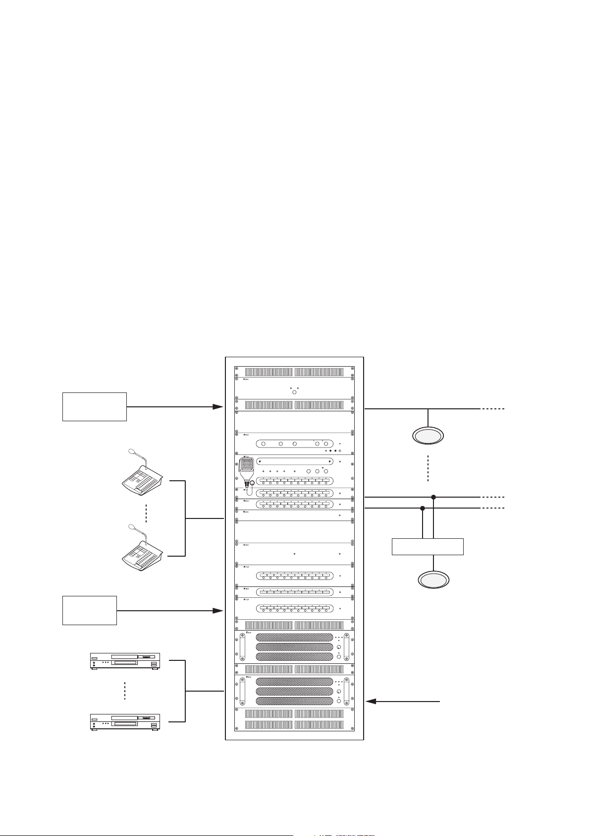
[System Diagram]
Automatic fire
alarm system
FS-7000RM
Up to 4 units
PBX
Floor identifier signal
Up to 200 zones Speaker line
Up to 200 zones
(Expandable in
10-zone units)
4-wire system control
Attenuator
Telephone paging
BGM player
Up to 4 units
230 V AC, 50 Hz
Page 8

8
3. FEATURES
• The FS-7000EV is loaded with English language messages when shipped from the factory.
• The semiconductor memory incorporated in the FS-7000EV ensures stable rebroadcast of recorded
messages.
• If speaker lines are shorted, the line protection fuse disconnects the shorted lines and a line short indication
is displayed.
• Simultaneous 2-channel broadcasts can be made of BGM (background music) and announcement
broadcasts (emergency and priority broadcasts), allowing BGM broadcasts to continue in zones not selected
for announcement broadcasts, even when announcements are being made.
• Up to 4 remote microphones can be connected.
• Up to 200 speaker lines can be controlled.
• Time signals can be simultaneously broadcast over all zones by connecting timer-operated sound sources.
• All-zone calls can be made from a telephone set by connecting the system to a telephone exchange.
• Connection of the emergency power supply panel permits emergency broadcasts to be made even during a
power failure.
4. HANDLING PRECAUTIONS
• When moving equipment from one place to another or when installing optional components in an equipment
rack, leave all necessary work to your TOA dealer.
• Ensure that the front and rear of the component are sufficiently distant from the wall to facilitate operation
and maintenance service.
• When cleaning components, be sure to first switch off the power, then wipe with a dry cloth. If they are very
dirty, use a cloth moistened in a neutral cleanser. Never use volatile liquids, such as benzene, thinner or
chemically-treated towels, since the component surface is damaged.
Page 9
9
5. NOMENCLATURE AND FUNCTIONS
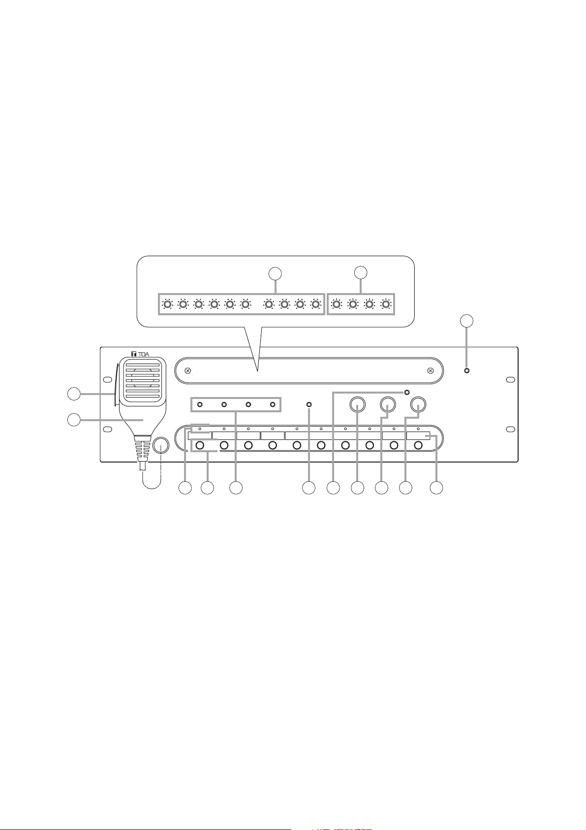
5.1. FS-7000CP Control Panel
The FS-7000CP is a standard operation panel for the FS-7000 Series Voice Evacuation Systems.
It is designed to be used in conjunction with the FS-7000JP panel, and enables individual paging calls to up to
10 zones plus all-zone calls.
The number of zones can be expanded to up to 200 zones in 10-zone units by connecting the FS-7010CP
expansion panel. Further, connection of both the FS-7000GM panel and the FS-7010CP panel permits
creation of up to 20 broadcast zone groups.
The FS-7000CP is equipped with a built-in pre-amplifier function and chime unit (ascending 4-note tone).
Audio output can be set to either a 2-channel output of background music (BGM) and priority broadcast or a 1channel output of mixed BGM and priority broadcast.
[Front]
1. Power Indicator
Lights when power is supplied and the FS7000CP is ready for operation.
2. CP Microphone
Make announcements while holding down the
Talk Switch (3). The microphone can be used only
while the FS-7000CP panel is in use or
emergency broadcasts are in progress.
3. Talk Switch
Hold down this switch to make announcements
using the microphone.
4. Volume Controls
Adjust the sound volume for each audio input.
Turning the control clockwise increases the
volume, while turning it counterclockwise
decreases the volume.
Controls are arranged from left to right as follows:
• EV
Adjusts the volume of the EV Audio Input on the
rear panel.
• TIMER
Adjusts the volume of the Timer Input on the rear
panel.
• PAGING
Adjusts the volume of the Paging Input on the rear
panel.
• RM MIC
Adjusts the volume of the RF Audio Input on the
rear panel.
• CP MIC
Adjusts the volume of the CP Microphone (2).
• CHIME
Adjust the volume of the built-in 4-tone chime.
• BGM 1 – 4
Adjusts the volume of BGM Inputs 1 – 4 on the
rear panel.
Inside of the front cover
3
2
7 9 10 11 12 136 148
4
5
1
Page 10

10
5. Tone Controls
Adjust high and low frequencies of the output.
Frequencies are accentuated when the control is
rotated clockwise, and attenuated when rotated
counterclockwise. Controls are arranged from left
to right as follows:
• PRIORITY BASS
Adjusts the low frequencies of the Priority Output
on the rear panel.
• PRIORITY TREBLE
Adjusts the high frequencies of the Priority Output
on the rear panel.
• BGM BASS
Adjusts the low frequencies of the BGM Output on
the rear panel.
• BGM TREBLE
Adjusts the high frequencies of the BGM Output
on the rear panel.
6. Zone Indicators
Light to indicate current broadcast zones.
Note
These indicators also light during emergency
broadcasts when broadcast zones are selected by
signal inputs from an automatic fire alarm system.
7. Zone Selector Keys
Press these keys to select broadcast zones. To
cancel the selection, press the keys again.
Multiple broadcast zones can be selected
simultaneously with the additional use of the FS7000GM panel.
8. Busy Status Indicators
The indicator corresponding to the component
currently in use for broadcast lights while the
system is in general-purpose broadcast mode.
Note
These indicators do not light during emergency
broadcasts.
The priorities of the indicators are: TIMER,
PAGING, RM MIC, and CP IN-USE from high to
low. (Emergency broadcasts take precedence
over all other equipment operations.)
Each indicator is arranged from left to right as
follows:
• TIMER
Remains lit during broadcasts from the component
connected to the timer input.
• PAGING
Remains lit during broadcasts from the
component connected to the paging input.
• RM MIC
Remains lit during broadcasts from the FS7000RM.
• CP IN-USE
Remains lit during broadcasts from the FS7000CP. Announcements can be made via the
CP Microphone (2).
9. Speaker Line Short Indicator
Lights when 1 or more speaker lines connected
to the FS-7000JP have shorted.
(See page 30.)
10. All-Zone Call Indicator
Lights when the All-Zone Call button (13) is
pressed to select all broadcast zones
simultaneously. (Lights continuously only while
the FS-7000CP is operating or emergency
broadcasts are being made.)
11. Chime Button
Sounds a built-in 4-tone chime. This button can
be used only while the FS-7000CP is operating.
12. Reset Button
Resets the broadcast zones selected with the
Zone Selector keys (7) or All-Zone Call button
(13). Pressing this button also terminates
general-purpose broadcasts provided from the
FS-7000CP.
13. All-Zone Call Button
Selects all broadcast zones simultaneously.
14. Broadcast Zone Fill-In Space
Write the names of zones to be selected with the
Zone Selector keys (7) in this space.
Page 11
11
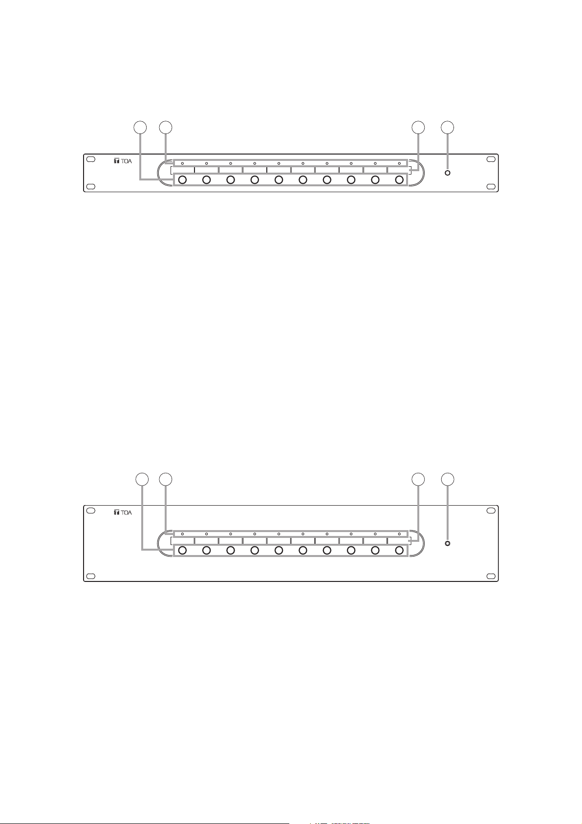
5.2. FS-7010CP Expansion Control Panel
The FS-7010CP is used to expand the broadcasting capacity of FS-7000 Series Voice Evacuation Systems.
Announcements and background music can be broadcast to up to 10 individual zones. Connecting the FS7000GM to the FS-7000CP/FS-7010CP combination permits broadcasts to be made to up to 20 zone groups.
[Front]
1. Power Indicator
Lights when power is supplied and the FS7010CP is ready for operation.
2. Zone Selector Keys
Press these keys to select broadcast zones. To
cancel the selection, press the keys again.
Multiple broadcast zones can be selected
simultaneously with the additional use of the FS7000GM.
3. Zone Indicators
Light to indicate current broadcast zones.
Note
These indicators also light during emergency
broadcasts when their corresponding zones are
selected by automatic fire alarm signals.
4. Broadcast Zone Fill-In Space
Write the names of zones to be selected with the
Zone Selector keys (2) in this space.
5.3. FS-7000JP Junction Panel
The FS-7000JP panel is used in conjunction with the FS-7000CP and the FS-7010CP to connect speaker
lines in FS-7000 Series Voice Evacuation Systems. It can connect up to 10 speaker lines. If speaker lines are
shorted, the line protection fuses disconnect the shorted lines, leaving broadcasts to other speaker lines
functioning intact. The FS-7000JP is equipped with BGM input and priority broadcast input, with BGM
broadcast zones selectable using the keys on the front panel. Priority broadcast zones are selected using the
FS-7000CP.
[Front]
1. Power Indicator
Lights when power is supplied and the FS-7000JP
panel is ready for operation.
2. BGM Zone Selector Keys
Press these keys to select BGM broadcast zones.
Press the keys again to cancel the selection. (2channel broadcast)
3. Speaker Line Indicators
Indicate speaker line operating statuses as
follows:
Green: BGM broadcast in progress (2-channel
broadcast)
Orange: BGM broadcast in progress (1-channel
broadcast) or priority or emergency
broadcasts in progress
Red: Short-circuit (see page 30.)
4. Broadcast Zone Fill-In Space
Write the names of zones to be selected with the
BGM Zone Selector keys (2) in this space.
2 3 4 1
4 12 3
Page 12
12
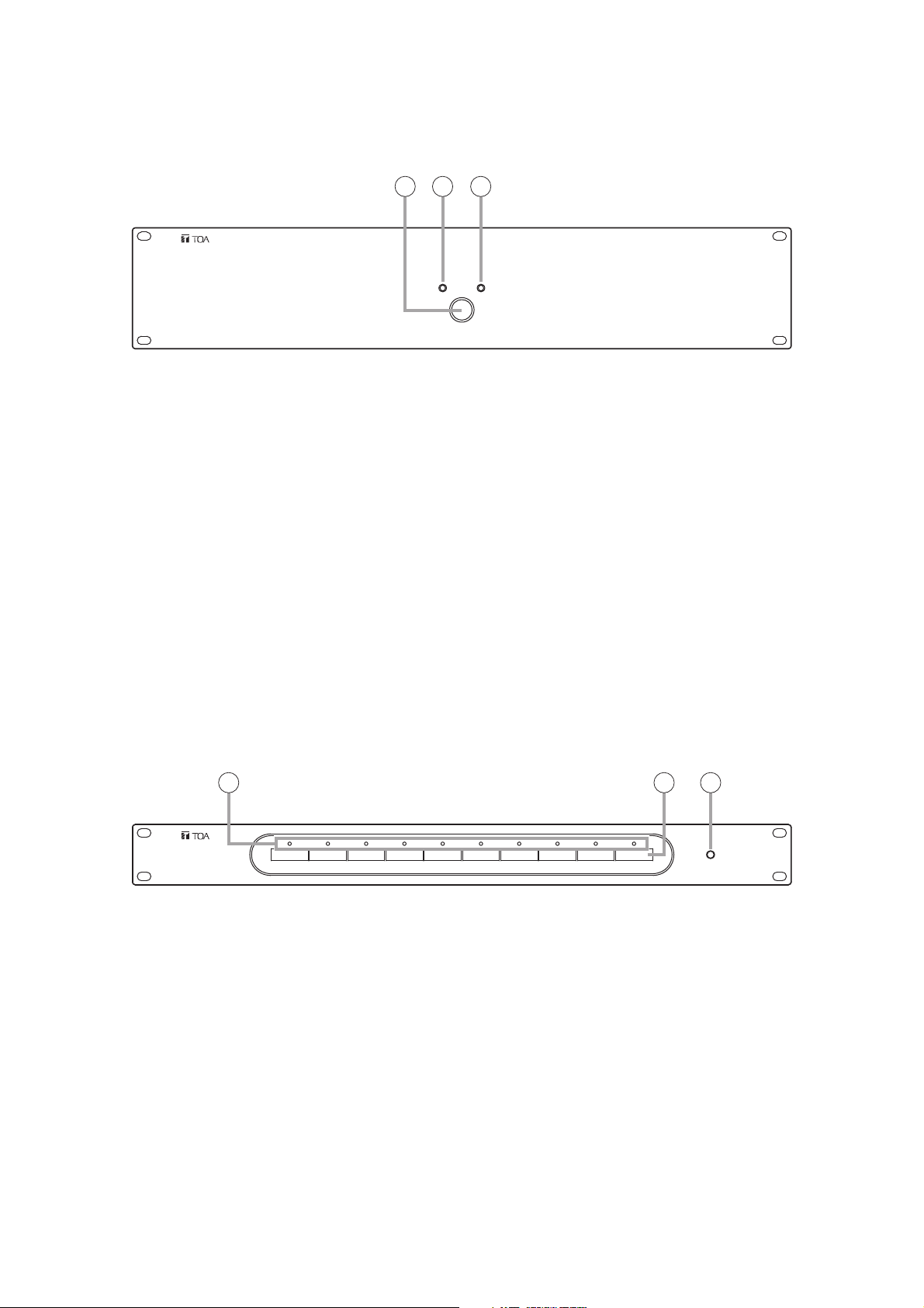
5.5. FS-7000AT Attenuator Control Panel
The FS-7000AT is used in conjunction with FS-7000 Series Voice Evacuation Systems to control 4-wire
system attenuators. Up to 10 zones can be attenuator-controlled. When general urgency or emergency
broadcasts are made, the FS-7000AT provides 24 V DC power to allow such broadcasts to bypass the
attenuators. The output status of each line can be monitored by the indicators on the front panel.
[Front]
1. Power Indicator
Lights when power is supplied and the FS-7000AT
is ready for operation.
2. Attenuator Line Indicators
Light when 24 V DC for bypassing the attenuators
are being supplied, and extinguish when the
overcurrent protection circuit is triggered due to
line shorts or other failures, or when the power
supply is cut off.
3. Broadcast Zone Fill-In Space
Write the names of the corresponding broadcast
zones in this space.
5.4. FS-7000PS DC Power Supply Panel
The FS-7000PS supplies 24 V DC power to each component used in FS-7000 Series Voice Evacuation
Systems. Connecting the DS-029B provides a power supply for emergency broadcasts even during power
failures.
[Front]
1. AC Power Switch
AC power is turned on and off with each press of
this switch.
2. AC Power Indicator
Lights when AC power is supplied and the FS7000PS is ready for operation on AC power.
3. DC Power Indicator
Lights when DC power is supplied and the FS7000PS is ready for operation on DC power.
1 2 3
2 3 1
Page 13

13
5.6. FS-7000EV Voice Evacuation Panel
The FS-7000EV is an emergency broadcast operation panel for FS-7000 Series Voice Evacuation Systems.
This panel is not required if the system is to be used solely for general-purpose public address applications. It
is possible to start and reset emergency broadcasts through manual operation. The FS-7000EV has a built-in
voice alarm device that can make both evacuation and false alarm announcements. Not only are evacuation
announcements automatically broadcast when the system receives a fire instruction signal from the connected
automatic fire alarm system, they can also be initiated using the Evacuation Announcement button on the front
panel. False alarm announcements can be initiated using the False Alarm Announcement button on the front
panel. Evacuation and false alarm announcement messages can also be recorded using the appropriate
buttons on the front of the panel, in which case the recorded message can be confirmed by listening with
headphones.
[Front]
1. Power Indicator
Lights when power is supplied and the FS7000EV is ready for operation.
2. Emergency Reset Button
When it is confirmed that a fire has been
extinguished or other emergency situations have
returned to normal, press this button to terminate
emergency broadcasts after resetting the
connected automatic fire alarm system.
3. Fire Indicator
Indicates that an emergency broadcast is in
progress. This indicator lights when a fire
detection signal is transmitted from the automatic
fire alarm system or when the Emergency
Activation button (4) is pressed.
4. Emergency Activation Button
Press this button to manually initiate emergency
broadcasts after the occurrence of fire has been
confirmed.
5. Mode Selector Switch
Selects the operation mode of the FS-7000EV unit
to be used as a sound source for evacuation and
false alarm announcements. Set the mode to
"NORMAL" in general use. No voice alarm is
output when the mode is set to "MONITOR" or
"RECORD."
Functions of the 3 switch positions are as follows:
NORMAL: Select this mode in general use. Voice
alarms are provided at the time of
emergency broadcast.
MONITOR: Allows the operator to listen to
messages recorded on a sound
source.
RECORD: Records evacuation and false alarm
announcements on a sound source.
(Default: NORMAL)
6. Evacuation Announcement Indicator
Lights or flashes when an evacuation
announcement is played back or recorded.
7. Evacuation Announcement Button
Press this button to play back or record
evacuation announcements.
8. False Alarm Announcement Indicator
Lights or flashes when a false alarm
announcement is played back or recorded.
9. False Alarm Announcement Button
Press this button to play back or record false
alarm announcements.
10. Input Sensitivity Setting Switch
Sets the input sensitivity of Recording Input (11).
Select the sensitivity depending on the type of
connected component.
(Default: –20 dBV)
11. Recording Input Terminal
Used for recording voice alarm messages.
(–60 dBV/2.2 kΩ or –20 dBV/10 kΩ selectable,
unbalanced, mini-jack)
12. Headphone Terminal
Connect headphones to this terminal to listen to
recorded messages for confirmation. Recorded
contents are output regardless of the settings of
the Mode Selector switch.
(0 dBV, 100 Ω, unbalanced, mini-jack)
13. Headphone Volume Control
Adjusts the volume of headphones.
2 3 4 7 8 9
165
10 11 12 13
Page 14

14
5.8. FS-7000RF Remote Microphone Interface Panel
The FS-7000RF is used to connect the FS-7000RM to FS-7000 Series Voice Evacuation Systems. Up to 4
FS-7000RM units can be connected using the FS-7000RF. It is possible to control 50 speaker lines as well as
all-zone calls. Connection of the FS-7000GM enables broadcasts to be made to up to 20 zone groups.
[Front]
1. Power Indicator
Lights when power is supplied and the FS7000RF is ready for operation.
2. Fault Indicator
Lights if any failure is detected in communications
with the FS-7000RM and flashes if any failure
occurs on the FS-7000RF itself. (See page 30.)
5.7. FS-7000GM Group Matrix Panel
The FS-7000GM panel is used in conjunction with FS-7000 Series Voice Evacuation Systems to make group
broadcasts. The FS-7000GM connects to the FS-7000CP and FS-7000RF and enables group broadcasts by
selecting multiple speaker lines simultaneously via the zone selector keys on the FS-7000CP or FS-7000RM.
Up to 20 groups and 50 speaker lines can be made available per unit, which can be expanded to 20 groups
and 200 speaker lines by connecting 4 units.
[Front]
1. Power Indicator
Lights when power is supplied and the FS7000GM is ready for operation.
1
2 1
Page 15

15
5.9. FS-7000RM Remote Microphone
The FS-7000RM Remote Microphone is used solely for general-purpose public address applications in FS7000 Series Voice Evacuation Systems. It enables broadcasting to up to 10 individual zones, as well as allzone calls. One FS-7000RF panel is required in order to connect the FS-7000RM to the system. Up to 4 FS7000RM units can be connected. Pressing the FS-7000RM's chime key causes the FS-7000CP's built-in 4tone chime to sound. Connection of 4 FS-7010RMs enables broadcasts to 50 individual zones as well as allzone calls (expandable by 10 lines per FS-7010RM). Further, up to 20 broadcast zone groups can be created
by connecting the FS-7000RF to an FS-7000GM Group Matrix Panel.
Tip
Connection of 6 FS-7010RM Remote Microphone Extension units enables broadcasting to 50 individual zones
and 20 zone groups, as well as all-zone calls.
[Top]
1. Power Indicator
Lights when power is supplied and the
FS-7000RM is ready for operation.
2. Fault Indicator
Lights when any failure is detected in
communications with the FS-7000RF or when any
failure occurs on the FS-7000RM itself.
(See page 30.)
3. All-Zone Call Indicator
Remains lit while an all-zone call is broadcast from
the FS-7000RM. (Lights only when calls are made
from this FS-7000RM.)
4. All-Zone Call Key
Selects all broadcast zones simultaneously.
5. Chime Key
Sounds a 4-tone chime built inside the FS7000CP.
6. Broadcast Reset Key
Resets broadcast zones selected via the All-Zone
Call key (4) or Zone Selector keys (11),
terminating broadcasts from the FS-7000RM.
7. Busy Indicator
Lights green when a broadcast is made from this
FS-7000RM, and lights orange when a broadcast
is made from other equipment.
8. Talk Key Indicator
Lights when a microphone announcement is made
using the Talk key (12).
9. Zone Identification Card
Write the names of the broadcast zones on this
card.
10. Zone Selection Indicators
Light when the corresponding Zone Selector
keys (11) are pressed. (Light only when the FS7000RM's keys are used.)
11. Zone Selector Keys
Select broadcast zones. Connection of the FS7000RF to the FS-7000GM permits simultaneous
selection of multiple broadcast zones.
12. Talk Key
Microphone announcements can be made only
while this key is pressed.
Tip
Key operation can be changed to allow
microphone announcements to alternate
between ON and OFF each time this key is
pressed. (Refer to the separate Installation
Manual.)
13. Microphone
1
3
13
5
7
9 10
11
2
4
6
8
12
Page 16

16
5.10. FS-7010RM Remote Microphone Extension
The FS-7010RM is an extension unit for the FS-7000RM to be used in FS-7000 Series Voice Evacuation
Systems. Ten zones can be expanded per FS-7010RM. Up to 6 FS-7010RM units can be connected to the
FS-7000RM.
[Top]
1. Zone Identification Card
Write the names of the broadcast zones on this
card.
2. Zone Selection Indicators
Light when the corresponding Zone Selector keys
(3) are pressed. (Only when zones are selected
from the FS-7010RM.)
3. Zone Selector Keys
Select broadcast zones.
1
2
3
Page 17

17
1. Power Switch
Press this switch to turn on the power. To turn off
the power, press this switch again.
2. Power Indicator
Lights when power is supplied and the FS7006PA/7012PA is ready for operation.
3. Volume Control
Adjusts the input signal level. This volume control
cannot be used while the Bypass Indicator (8)
continuously lights.
4. Fill-In Space
Write uses of the main and standby amplifiers in
this space.
5. Fault Indicator
Lights when an output muting function* is
operated or when a failure is detected.
If the YA-7000 is used, this indicator lights when
the YA-7000 detects a failure and the power
amplifier is switched over to a standby amplifier.
(See page 30.)
* This function prevents noise from being
generated when power is switched on and off.
6. Signal Indicator
Lights when a signal that exceeds a level 24 dB
below the rated output is sent to the Speaker
Output on the rear panel.
7. Peak Indicator
Lights when a signal that exceeds a level of 3 dB
below the rated output is sent to Speaker Output
on the rear panel.
8. Bypass Indicator
Lights when the Volume Bypass Control Input on
the rear panel is enabled and indicates that the
Volume Control (3) has been bypassed and
disabled.
5.11. FS-7006PA/7012PA Power Amplifiers
These power amplifiers are used in conjunction with FS-7000 Series Voice Evacuation Systems. The FS7006PA's output is rated at 600 W and the FS-7012PA is rated to deliver 1,200 W. By mounting the YA-7000
module in a power amplifier and connecting a standby amplifier to it, the power amplifier can be automatically
switched over to the standby amplifier if the power amplifier fails. When initiating emergency broadcasts, the
volume control on the front panel is bypassed by closing the Volume Bypass Control terminals on the rear
panel, allowing broadcasts of emergency message at maximum volume.
[Front]
Figure shows the FS-7012PA.
5.12. YA-7000 Amplifier Auto Switching Module
The YA-7000 module is designed to be mounted in the power amplifier of FS-7000 Series Voice Evacuation
Systems. Connecting a standby amplifier to the YA-7000 module installed in the main amplifier (FS-7006PA or
FS-7012PA) permits the main amplifier to be switched over to the standby amplifier if the main amplifier fails.
[Front]
7
65
8
3
2
4
1
Page 18

18
6.
FUNCTIONS & OPERATION OF EMERGENCY/GENERAL-PURPOSE BROADCASTS
6.1. Emergency Broadcasts
A system that integrates the FS-7000EV allows emergency broadcasts to be made automatically, through
connection to an automatic fire alarm system, or manually via the FS-7000CP unit in the main rack system.
When implementing an emergency broadcast, volume controls on the front panels of the FS-7006PA and FS7012PA amplifiers are bypassed to allow broadcast of the emergency message at maximum volume.
Systems equipped with an FS-7000AT can supply 24 V DC power to the 4-wire system attenuators in order to
bypass them.
Emergency broadcasts have the highest priority.
When an emergency broadcast is activated, the following occurs:
• In the emergency broadcast area: General-purpose broadcasts* are stopped to allow the emergency
broadcast to be heard.
• Other areas: If the system has been set to a 1-channel broadcast mode, general-
purpose broadcasts are stopped.
If the system has been set to a 2-channel broadcast mode, priority
broadcasts are stopped but BGM broadcasts continue.
When an emergency broadcast ends, the following occurs:
• In the BGM broadcast area:
The broadcast does not return to its original state if the system has been set to 1-channel broadcast mode.
The broadcast returns to its original state if the system has been set to 2-channel broadcast mode.
If a priority broadcast was already in progress when an emergency broadcast is activated:
• If the broadcast was from the microphone of the FS-7000CP, then it will not be resumed.
The broadcast area must be selected again when making a microphone announcement.
• If the broadcast was from the FS-7000RM, then it will return to its original state.
• If the broadcast was a telephone paging or timer-activated automatic broadcast, the broadcast will resume if
the paging operation or timer input activation still continues.
*Refer to "Types of General-Purpose Broadcasts" explained in the following section.
6.2. General-Purpose Broadcasts
6.2.1. Types of General-Purpose Broadcasts
General-purpose broadcasts can be classified as follows, depending on the type of equipment, broadcast
priority, etc.
[Timer-activated automatic broadcasts]
When the Timer Input on the rear of the FS-7000CP receives an audio signal and a control signal from a
music play component, the broadcast is made to all zones during operation of the music play component.
[Telephone paging]
When the Paging Input on the rear of the FS-7000CP receives an audio signal and a control signal from a
telephone exchange, a paging call from a telephone set is made to all zones.
(Listed by priority)
General-Purpose
Broadcasts
Priority
Broadcasts
BGM
Broadcasts
Timer-activated automatic broadcasts
Telephone paging
FS-7000RM broadcasts (when using the FS-7000RF and FS-7000RM)
Microphone announcements from the FS-7000CP
Page 19

19
[Announcements from the FS-7000RM (with the FS-7000RF and FS-7000RM installed)]
Microphone announcements can be made to specific areas selected using the Zone Selector Keys on the FS7000RM or FS-7010RM. Also, pressing the Chime Key on the remote microphone before making the
announcement causes the FS-7000CP's 4-tone chime to sound.
[Microphone announcements from the FS-7000CP]
Microphone announcements can be made to specific areas selected using the Zone Selector Keys on the FS7000CP or FS-7010CP. Also, pressing the Chime Button on the FS-7000CP before making the
announcement causes the 4-tone chime to sound. Microphone announcements are broadcast after they have
been mixed with signals from the sound source equipment connected to the Auxiliary Input on the rear of the
FS-7000CP.
[BGM Broadcasts]
For systems equipped with a 2-channel power amplifier and capable of 2-channel broadcasting, the BGM
Zone Selector Keys on the FS-7000JP may be used to select broadcast areas, allowing broadcasts from the
music play component connected to the FS-7000CP's BGM input.
For systems equipped with a 1-channel power amplifier and capable of 1-channel broadcasting, the BGM
broadcast areas can be selected at the FS-7000CP or FS-7010CP.
6.2.2. BGM Broadcasts & Priority Broadcasts
If a priority broadcast is made to an area in which BGM broadcasting is in progress, the BGM broadcast is
interrupted and changed to the priority broadcast. Once the priority broadcast has finished, the original BGM
broadcast resumes immediately.
[Broadcasting to areas in which BGM broadcasting is in progress]
2-Channel Broadcasting
[Broadcasts from sources other than the FS-7000CP]
The BGM broadcast is interrupted and changed to the priority broadcast. Once the priority broadcast has
finished, the original BGM broadcast resumes gradually.
1-Channel Broadcasting
[Broadcasts from the FS-7000CP]
The BGM broadcast is interrupted by microphone announcement or chime play and changed to the priority
broadcast. Once the priority broadcast has finished, the original BGM broadcast resumes gradually.
Priority broadcast start Priority broadcast end
BGM broadcast Priority broadcast BGM broadcast
Priority broadcast start Priority broadcast end
BGM broadcast Priority broadcast BGM broadcast
Broadcast start Broadcast end
BGM broadcast BGM broadcast
Microphone announcement
or chime play
Page 20

20
6.2.3. Order of Priority among Priority Broadcasts
Priority broadcasts are not broadcast all at once; rather, they are issued one at a time following a specific
order of priority, as follows.
Example: If a timer-activated automatic broadcast is in progress, only that broadcast will be performed, and
other broadcasts will not be made.
[Order of priority among the FS-7000RM units
]
When multiple FS-7000RM units are connected, the following modes are available for determining broadcast
priority among them. Select the desired mode using the Function Switch on the rear of the FS-7000RF.
• Last-in-first-out (LIFO): Priority is given to the FS-7000RM unit that last selected a broadcast area.
• First-in-first-out (FIFO): Priority is given to the FS-7000RM unit that first selected a broadcast area, and
broadcasts from other FS-7000RM units are not possible until that broadcast has
been finished.
• Individual: Priority is given to the FS-7000RM unit with the lowest address number.
• None: All of the FS-7000RM units that have selected a broadcast area can make
broadcasts. In this event, all of the audio signals output from all of the FS-7000RM
units will be mixed.
[When a higher-priority broadcast occurs during a priority broadcast]
• In areas with the higher-priority broadcast: The lower-priority broadcast is interrupted to allow the higher-
priority broadcast to go through.
• In other areas: If the system has been set to 1-channel broadcasting, the
general-purpose broadcast is stopped.
If the system has been set to 2-channel broadcasting, the
priority broadcast already in progress is interrupted, but BGM
broadcasts continue.
When the higher-priority broadcast is finished, other broadcasts resume as follows:
• BGM broadcasts: Return to original state.
If other high-priority broadcasts were in progress:
• Announcements from the FS-7000CP microphone resume.
• Announcements from the FS-7000RM resume.
• Telephone paging resumes if the paging is still being operated.
6.2.4. "Normal" Mode and "Urgency" Mode All-Zone Calls
All-zone calls originating from the FS-7000CP or FS-7000RM are available in 2 modes: "Normal" and
"Urgency." For the FS-7000CP, set the desired all-zone call mode using the All-Zone Call Mode Selector
Switch on its rear panel, and for the FS-7000RM, use the Function Switch on the rear of the FS-7000RF. All
all-zone call* broadcasts will be made using whichever mode has been set.
• Normal Mode: Broadcast volume can be controlled by the attenuator.
• Urgency Mode: The attenuator volume control is bypassed, allowing broadcasts in all areas to be made at
maximum volume. (This assumes installation of the FS-7000AT.)
*Announcements made using the All-Zone Call Button on the FS-7000CP or the All-Zone Call Key on the FS-
7000RM.
Higher priority Lower priority
Timer-activated
automatic broadcasts
Telephone paging
General-purpose
broadcasts from
the FS-7000RM
Microphone
announcements
from the FS-7000CP
Page 21

21
7. MAKING EMERGENCY BROADCASTS
7.1. Initiating Emergency Broadcasts Manually
Under manual operation, the broadcast areas are selected and the broadcast is conducted using either a
microphone or the pre-recorded voice alarm messages stored in the FS-7000EV.
[Buttons and keys used for operation]
[FS-7000EV]
[FS-7000CP]
[FS-7010CP]
Step 1. Press the Emergency activation button on the FS-7000EV.
The Fire indicator will light.
2-channel broadcast: Broadcasting is stopped in areas where priority broadcasts are underway.
BGM broadcasting continues.
1-channel broadcast: Broadcasting is stopped in all areas.
Step 2. Use the Zone selector keys on the FS-7000CP or FS-7010CP to select the broadcast areas.
The appropriate Zone indicators will illuminate.
2-channel broadcast: BGM broadcasting in the selected areas is stopped.
Talk Switch
Emergency
Reset Button
Fire Indicator Evacuation
CP Microphone
Emergency
Activation Button
Zone Selector Keys Zone Indicators
Evacuation Announcement
Indicator
Announcement Button
Zone Selector Keys Zone Indicators
Page 22

22
Step 3. Activate emergency evacuation announcements.
Press the Evacuation announcement button.
The Evacuation announcement indicator will illuminate and the evacuation announcement will be sent
to all selected areas.
To stop the evacuation announcement, press the Evacuation announcement button again.
Broadcast using the microphone on the FS-7000CP.
Make the desired announcement while pressing the Talk switch of the microphone.
Announcements made using the microphone will override any pre-recorded voice alarm broadcasts
being made via the FS-7000EV. These pre-recorded message broadcasts will resume once the
microphone announcement has finished.
Step 4. Once the fire has been extinguished, press the Emergency reset button on the FS-7000EV to
terminate emergency broadcasts.
The Fire indicator and Evacuation announcement indicator will extinguish, and original generalpurpose broadcasts will resume automatically.
Note
Priority broadcasts from the CP-7000CP and 1-channel BGM broadcasts will not resume
automatically.
[Pre-recorded voice alarm messages set at the factory are as follows]
Evacuation announcement:
"There is a fire. Please evacuate as quickly as possible."
False alarm announcement:
"Attention please. A few minutes ago we announced there may be a fire. However, there is no fire.
Once again, there is no fire."
Using the microphone
Using pre-recorded voice alarm messages stored in the FS-7000EV
Page 23

23
7.2. Initiating Emergency Broadcasts by Fire Alarm System
If the broadcast system is connected to an automatic fire alarm system, then whenever a fire is detected, the
Fire indicator will illuminate and the FS-7000EV's pre-recorded evacuation announcements will commence
automatically. Operation procedures following the start of such emergency announcements are as follows.
[Buttons and keys used for operation]
[FS-7000CP]
[FS-7010CP]
[FS-7000EV]
Using the Zone selector keys on the FS-7000CP and FS-7010CP, select broadcast areas other than
those automatically selected by the fire alarm system.
The appropriate Zone indicators will illuminate.
Broadcast using the microphone on the FS-7000CP.
Make the desired announcement while pressing the Talk switch of the microphone.
Announcements made using the microphone will override any pre-recorded voice alarm broadcasts being
made via the FS-7000EV. These pre-recorded messages will resume once the microphone announcement
has finished.
Broadcasting announcements via microphone
Manually selecting broadcast areas
Talk Switch
Fire Indicator
CP Microphone
Emergency
Reset Button
Zone Selector Keys Zone Indicators
Zone Selector Keys Zone Indicators
Evacuation
Announcement Button
Evacuation Announcement
Indicator
False Alarm
Announcement Button
False Alarm
Announcement Indicator
Page 24

24
Press the Evacuation announcement button on the FS-7000EV.
The Evacuation announcement indicator will extinguish and the evacuation announcement will be stopped.
To resume the evacuation announcement, press the Evacuation announcement button again.
Tip
If an additional fire instruction signal is received from the automatic fire alarm system:
• The appropriate broadcast areas are selected and the Zone indicators illuminate.
• If no evacuation announcement is already in progress, then the additional instruction signal activates
evacuation announcements automatically.
After the automatic fire alarm system has been reset, press the Emergency reset button on the FS7000EV.
The Fire indicator and Evacuation announcement indicator will extinguish, and original general-purpose
broadcasts will resume automatically.
Tip
Priority broadcasts from the FS-7000CP unit and 1-channel BGM broadcasts will not resume automatically.
Activate the false alarm announcement by pressing the False alarm announcement button on the FS7000EV.
The False alarm announcement indicator will illuminate and the false alarm announcement will be sent.
Then, after resetting the automatic fire alarm system, press the Emergency reset button on the FS7000EV.
The Fire indicator will extinguish, and original general-purpose broadcasts will resume.
Tip
Priority broadcasts from the FS-7000CP unit and 1-channel BGM broadcasts will not resume automatically.
Making false alarm announcements
Terminating emergency announcements once a fire has been extinguished
Temporarily stopping evacuation announcements
Page 25

25
7.3. Recording Voice Alarm Messages
To record customized evacuation and false alarm announcements to the FS-7000EV, connect a microphone
or music play device to the Recording input terminal on the front panel of the FS-7000EV. Up to 2 messages
with a combined total duration of about 3 minutes can be recorded. Since the recording circuit is equipped
with an AGC circuitry, it is not necessary to adjust the recording level.
If the Mode Selector Switch remains in the "RECORD" or "MONITOR" position, the recorded audio message
will not be output from the broadcast audio output. Therefore, it is important to reset this switch to "NORMAL"
once recording or monitoring has finished.
[Buttons and switches used for operation]
[FS-7000EV]
7.3.1. Recording
The signal that has entered the Recording input terminal is output to the Headphone terminal only, and will not
be output through the broadcast audio output.
Note
Operating the recording function with no device connected to the Recording input terminal will record nothing,
and the previous recorded message is not erased.
Step 1. Set the Mode selector switch to "RECORD."
Step 2. Set the Input sensitivity setting switch at the desired level. Use –60 dBV (to the left) for microphone
input and –20 dBV (to the right) for all other inputs.
Step 3. Connect the microphone or CD player (or other component) to the Recording input terminal.
Step 4. Press and hold the Evacuation announcement (or False alarm announcement) button until the
Evacuation announcement (or False alarm announcement) indicator begins to flash. Begin recording
as soon as the flashing of this indicator changes to continuous illumination.
Be sure to press the Evacuation announcement button to record an evacuation announcement and
the False alarm announcement button to record a false alarm announcement. The new message will
overwrite any existing messages.
Note
The indicator will begin to flash after the button is pressed for about 1 second, and after about 2
seconds the flashing will change to continuous illumination.
Step 5. To stop recording, press the same button (Evacuation announcement button or False alarm
announcement button) again.
When the remaining available recording time has been reduced to 5 seconds, the Evacuation
announcement (or False alarm announcement) indicator will begin flashing and will continue flashing
until recording is finished.
Step 6. Once recording is finished, reset the Mode selector switch to "NORMAL."
Evacuation Announcement Button
Evacuation Announcement Indicator
Mode Selector Switch
Input Sensitivity Setting Switch
False Alarm Announcement Indicator
False Alarm Announcement Button
Headphone Terminal
Recording Input Terminal
Page 26

26
7.3.2. Checking Recorded Content
Connect headphones to the Headphone terminal.
Step 1. Set the Mode selector switch to "MONITOR."
The Evacuation announcement indicator and False alarm announcement indicator will begin to flash.
Step 2. Press the appropriate Evacuation announcement button or False alarm announcement button to listen
to the recorded content.
The flashing of the Evacuation announcement indicator or False alarm announcement indicator will
change to continuous illumination and playback of the recording will begin.
Note
Changing the Mode selector switch to another position during recording playback will terminate
playback. Also, note that the recording being played back will only be audible through the
headphones, and will not be output through the broadcast output terminal.
Step 3. To stop playback of the recording, press the same button (Evacuation announcement button or False
alarm announcement button) again.
The Evacuation announcement indicator and False alarm announcement indicator will begin to flash.
Step 4. Once monitoring is finished, reset the Mode selector switch to "NORMAL."
The Evacuation announcement indicator and False alarm announcement indicator will extinguish.
Page 27

27
8. MAKING GENERAL-PURPOSE BROADCASTS
8.1. Making General-Purpose Broadcasts from the FS-7000CP
[Buttons and keys used for operation]
[FS-7000CP]
[FS-7010CP]
Step 1. Press the appropriate Zone selector keys or All-zone call button on the FS-7000CP and FS-7010CP
to select the desired broadcast zones.
The appropriate Zone indicators or All-zone call indicator will illuminate.
Step 2. If the CP IN-USE indicator is illuminated, press the Chime button to sound the chime.
If other Busy indicator, or the Fire indicator on the FS-7000EV is illuminated, then a higher-priority
broadcast is in progress, and broadcasts cannot be made from the FS-7000CP. Wait until the higherpriority broadcast is finished and try again.
Step 3. Press the Talk switch of the microphone continuously and make the announcement.
The microphone announcement is broadcast only while the Talk switch is depressed.
Note
When a higher-priority broadcast is made while a general-purpose broadcast from the FS-7000CP is
already in progress (the Busy indicator except CP IN-USE indicator or the FS-7000EV's Fire indicator
will illuminate), the general-purpose broadcast will be suspended. In some cases, the original
broadcast will not resume even after the higher-priority broadcast is completed. In such cases,
perform operation again from the beginning.
Step 4. Press the Reset button to finish broadcasting.
Note
When BGM is being played in 1-channel broadcast mode, if the chime is sounded or microphone
announcements are made without designating their specific broadcast areas, these will be heard in
the areas where BGM play is in progress. To avoid this, select the desired chime or microphone
announcement areas before broadcasting. Since such broadcasts disable BGM play, select the areas
that will require continued BGM after the chime or microphone announcement has been completed.
Busy Status Indicators
(CP IN-USE)
Talk Switch Chime Button
CP Microphone Zone Selector Keys Zone Indicators
Zone Selector Keys Zone Indicators
Reset Button
All-Zone Call
Indicators
All-Zone Call
Button
Page 28

28
8.2. Making Announcements from the FS-7000RM
[Keys used for operation]
Step 1. Press the appropriate Zone selector keys or All-zone call key on the FS-7000RM or FS-7010RM to
select the desired broadcast areas.
The appropriate Zone indicators or All-zone indicator will illuminate.
Step 2. If the Busy indicator is illuminated green, press the Chime button to sound the chime.
If the Busy indicator is illuminated orange, then another higher-priority broadcast is in progress, and
broadcasts cannot be made from the FS-7000RM.
Wait until the higher-priority broadcast is finished and try again.
Step 3. Press the Talk key continuously and make the announcement using the microphone. The
announcement is broadcast only while the Talk key is depressed.
Note
If a higher-priority broadcast is made while the announcement from the FS-7000RM is underway, then
the In-Use indicator will illuminate orange and the announcement will be suspended. In such cases,
simply wait until the higher-priority broadcast is finished and try again.
Tip
It is possible to change the Talk key from "PTT" (Press-to-Talk) operation (which allows the user to
speak only while the key is continuously pressed) to "Alternate" operation (which alternates the
microphone between ON and OFF with each press of the key).
(For changing the key operation, refer to the separate Installation Manual.)
Step 4. Press the Broadcast reset key to finish broadcasting.
[FS-7000RM] [FS-7010RM]
All-Zone Call Indicator
All-Zone Call Key
Chime Key
Zone Selection
Indicators
Microphone
Busy Indicator
Broadcast Reset Key
Talk Key
Zone Selector Keys
Page 29

29
8.3. Making BGM Broadcasts
The operating panel used will differ depending on whether the system is set to 1-channel or 2-channel
broadcast mode.
Note
Use the Output mode selector switch on the rear of the FS-7000CP to switch between 1-channel and 2channel broadcast mode.
[Buttons and keys used for operation]
[FS-7000CP]
[FS-7010CP]
[FS-7000JP]
8.3.1. When using 1-channel broadcasting
Press the appropriate Zone selector keys or All-zone call button on the FS-7000CP or FS-7010CP to
select the desired broadcast areas, then commence music play from the BGM device.
The appropriate Zone indicators or All-zone call indicator will illuminate.
8.3.2. When using 2-channel broadcasting
Press the appropriate BGM Zone selector keys on the FS-7000JP to select the desired broadcast
areas, then commence music play from the BGM device.
The appropriate Zone indicators will illuminate.
All-Zone Call
Indicator
Zone Selector Keys
Zone Selector Keys Zone Indicators
Zone Indicators
All-Zone Call
Button
Speaker Line IndicatorsBGM Zone Selector Keys
Page 30

30
9. FAILURE INDICATION
The FS-7000CP, FS-7000JP, FS-7000RF, FS-7000RM, FS-7006PA, and FS-7012PA are equipped with
failure indicators that show the status of any problems that may occur. When such an indicator lights or
flashes, it means that a problem may have occurred in the equipment or in the wiring.
If the power indicator is not illuminated, the equipment could be malfunctioning. In such cases, check to see if
power is being supplied correctly, or if a fuse has blown. A blown fuse often means that the problem may have
occurred within the wiring as well as in the equipment itself.
In such cases, replace the fuse(s) and check the correctness of the wiring before turning the power on again.
If an indicator lights continuously or flashes, the following possible causes may be considered:
Symptom Possible Cause Check/Remedy
One or more of the speaker lines have
shorted, causing the associated line
protection fuse of FS-7000JP to blow.
FS-7000CP's
Speaker Line Short
indicator lights.
FS-7000JP's
Speaker Line
Indicator lights red.
The speaker line corresponding to the FS7000JP's Speaker Line indicator that
continuously lights red may be shorted.
Locate and fix the speaker line short,
replace the line protection fuse, then press
the Reset switch mounted on the rear
panel of the FS-7000JP.
Communications are not being
performed correctly with the FS7000RM units of the number
designated using the setting switch, or
equipment failures may have occurred.
Communication with the FS-7000RF is
not being performed correctly, or
equipment failures may have occurred.
FS-7000RF's Fault
indicator lights red.
FS-7000RF's Fault
indicator flashes
red.
FS-7000RM's Fault
indicator lights.
• Confirm that the number that has been
set using the setting switch agree with
the actual number of the connected FS7000RM units.
• Confirm that the FS-7000RM's address is
set correctly.
• Confirm that there is no fault with the
wiring leading to the FS-7000RM.
If all of the above are found to be in
correct working order, then it is likely that
the FS-7000RM itself is malfunctioning.
It is likely that the FS-7000RF itself is
malfunctioning.
• Confirm that the number of units that has
been set using the FS-7000RF's setting
switch agrees with the actual number of
the FS-7000RM units connected.
• Confirm that the unit has the correct
address settings.
• Confirm that there is no fault with the
wiring leading to the FS-7000RF.
If all of the above are found to be in
correct working order, then it is likely that
the FS-7000RF itself is malfunctioning or
equipment failures may have occurred.
Output is not being provided correctly
because of a short in the output wiring.
FS-7006PA's or
FS-7012PA's Fault
indicator lights.
– Continued on
next page –
Remove the output wiring and turn the
power on again. If the fault indicator light
goes out, then the problem may be with
the wiring. Check the wiring to determine
where the problem may be.
If the indicator light does not go out, or if it
goes out but then lights again within a
short period of time, consider whether the
following may be the problem:
Page 31

31
Symptom Possible Cause Check/Remedy
FS-7006PA's or
FS-7012PA 's Fault
indicator lights.
Equipment failure or excessive high
heat build-up inside the unit.
YA-7000's Operation Mode Selector
switch was set to "Test" during its
installation.
Check the following points if the indicator
automatically goes out within 30 minutes
after it has lit.
• Check installation conditions for
appropriate ventilation.
• Check the connected load capacity for
possible overload.
• Check to see if input and output cables
are installed in close proximity to each
other.
If all of the above are found to be in
correct working order, then it is likely that
the equipment itself is malfunctioning in
some way.
Equipment failures can also be considered
if the indicator lights again within a short
period of time even if it has gone out once.
Request maintenance and repair action.
Set the mode switch to "Normal."
Symptom
No sound.
Items to Check
[FS-7000CP/7006PA/7012PA]
Is the volume control set to "0"?
[FS-7000CP/7010CP/7000JP/
7000RM/7010RM]
Is the broadcast area selected?
Potential Solution
Turn the volume knob clockwise and
set the volume to the appropriate level.
Press the Zone selector key to select a
broadcast area.
Cannot record a voice
message.
The recorded sound
volume is too low or is
distorted.
Cannot bypass the
attenuator to
broadcast at maximum
volume.
[FS-7000CP]
Is a higher-priority broadcast already in
progress?
[FS-7000EV]
Is a microphone or other sound source
correctly connected to the Recording
input terminal?
[FS-7000EV]
Is the Input sensitivity setting switch set
to the correct level at the time of
recording?
[FS-7000AT]
Is the FS-7000AT's attenuator line
indicator illuminated when attempting to
make emergency or general urgency
broadcasts?
Wait until the higher-priority broadcast
has finished and try again.
Try removing and reinserting the plug
into the recording input jack.
Set the Input sensitivity setting switch to
–60 dB (to the left) when using a
microphone and –20 dBV (to the right)
when connecting other components.
It is likely that 24 V DC power is not being
properly supplied to the attenuator.
Contact your TOA dealer to have the unit
inspected.
10. TROUBLESHOOTING
If the power will not go on, no sound is output, or other problem occurs, check the following list of
troubleshooting symptoms and solutions. If the symptoms still persist, then refer the problem to the store from
where the component was purchased.
Page 32

32
11. SPECIFICATIONS
11.1. FS-7000CP Control Panel
24 V DC, M3 screw terminal, distance between barriers: 6.4 mm
200 mA
EV: 0 dB*, 600 Ω, unbalanced, removable terminal block (2 pins)
Timer: 0 dB*, 600 Ω, unbalanced, removable terminal block (4 pins)
Paging: –60/–20 dB*, 600 Ω, balanced, removable terminal block (5 pins)
RF (Remote microphone): 0 dB*, 600 Ω, balanced, removable terminal block (3 pins)
Preinstalled microphone (accessory): –55 dB*, 600 Ω, unbalanced,
circular connector (4 pins)
AUX: –20 dB*, 600 Ω, unbalanced, removable terminal block (2 pins)
BGM 1: –60/0 dB*, 600 Ω, balanced, removable terminal block (3 pins)
BGM 2 – 4: –20 dB*, 10 kΩ, unbalanced, RCA jack
Priority output: 0 dB*, 600 Ω, balanced, removable terminal block (3 pins)
(Outputs signals other than BGM 1 – 4 input signals when output
is set to 2-channel broadcast mode.)
BGM output: 0 dB*, 600 Ω, balanced, removable terminal block (3 pins)
(Outputs BGM 1 – 4 signals.)
50 – 15,000 Hz, within ±3 dB (1 kHz)
±10 dB at 100 Hz and 10 kHz
Over 60 dB
Under 1%
Priority output:
Preinstalled microphone > EV (emergency broadcast mode)
Timer > Paging > Remote microphone > Preinstalled microphone,
AUX > BGM 1 ≥ BGM 2 – 4 (general-purpose broadcast mode)
BGM output: BGM 1 ≥ BGM 2 – 4 (by muting function setting)
Ascending 4-tone chime
Timer: No-voltage make contact input, open voltage: 26 V DC, short-circuit
current: under 2 mA, removable terminal block (4 pins)
Paging: No-voltage make contact input, open voltage: 26 V DC, short-circuit
current: under 2 mA, removable terminal block (5 pins)
Automatic fire alarm system (10 zones):
No-voltage make contact input, open voltage: 26 V DC,
short-circuit current: under 5 mA, removable terminal block (12 pins)
10 individual zones + all-zone call or 10 group zones + all-zone call (when
optional FS-7000GM is connected)
(individual zones expandable to up to 200 zones using FS-7010CP)
Zone selection keys, All-zone call button (general-purpose/general urgency allzone call selectable), Broadcast reset button and Chime button
Power indicator, All-zone call indicator, Zone indicators, Busy indicator (timer,
paging, remote microphone and main system), Speaker line short-circuit indicator
0°C to +40°C
Under 90% RH (no condensation)
Panel: Aluminum, black, alumite
482 (w) x 132.6 (h) x 376.9 (d) mm
5.2 kg
Power Source
Current Consumption
Input
Output
Frequency Response
Tone Control
S/N Ratio
Distortion
Priority Function
Electronic Tone
External Control Input
Output Control
Operating Section
Display Section
Operating Temperature
Operating Humidity
Finish
Dimensions
Weight
* 0 dB = 1 V
Note: The design and specifications are subject to change without notice for improvement.
• Accessories
Microphone ................................................ 1
Removable terminal plug (2 pins) .............. 2
Removable terminal plug (3 pins) .............. 4
Removable terminal plug (4 pins) .............. 1
Removable terminal plug (5 pins) .............. 1
Removable terminal plug (12 pins) ............ 1
Page 33

33
11.2. FS-7010CP Expansion Control Panel
24 V DC, M3 screw terminal, distance between barriers: 6.4 mm
150 mA
Automatic fire alarm system (10 zones):
No-voltage make contact input, open voltage: 26 V DC,
short-circuit current: Under 5 mA, removable terminal block (12 pins)
10 individual zones or 10 group zones (when optional FS-7000GM is connected)
Zone selection keys
Power indicator, Zone indicators
0°C to +40°C
Under 90% RH (no condensation)
Panel: Aluminum, black, alumite
482 (w) x 44 (h) x 337 (d) mm
3 kg
Power Source
Current Consumption
External Control Input
Output Control
Operating Section
Display Section
Operating Temperature
Operating Humidity
Finish
Dimensions
Weight
Note: The design and specifications are subject to change without notice for improvement.
• Accessories
Connection cable (14 pins, 60 cm) ............. 1
Connection cable (10 pins, 2.5 m) ............. 1
Removable terminal plug (12 pins) ............ 1
Page 34

34
11.3. FS-7000JP Junction Panel
24 V DC, M3 screw terminal, distance between barriers: 6.4 mm
450 mA
Priority input: 100 V line: Max. 1200 W, M4 screw terminal,
distance between barriers: 9 mm
BGM input: 100 V line: Max. 1200 W, M4 screw terminal,
distance between barriers: 9 mm
10 lines each for H and C, M3 screw terminal, distance between barriers: 6.4 mm
(100 V line, Max. 280 W for FS-7006PA, Max. 500 W per line for FS-7012PA)
ø5 mm tubed fuse 0.5 A x 10 fuses preinstalled
(Fuse capacity must be changed depending on the load capacity.)
General urgency/Emergency mode output terminal:
Open collector output, rated voltage: 30 V DC, current capacity: 0.1 A,
removable terminal block (2 pins)
Power remote output terminal:
Relay contact output, rated voltage: 30 V DC, current capacity: 1 A,
removable terminal block (2 pins)
BGM zone selection keys
Power indicator, Speaker line indicators (Green: BGM in progress (2-channel
broadcast mode)/ Orange: BGM in progress (1-channel broadcast mode),
priority broadcast, and emergency broadcast/ Red: short-circuit)
0°C to +40°C
Under 90% RH (no condensation)
Panel: Aluminum, black, alumite
482 (w) x 88.4 (h) x 340.7 (d) mm
4.2 kg
Power Source
Current Consumption
Power Amplifier Input
Speaker Output
Line Short-Circuit
Protection
External Control
Onput
Operating Section
Display Section
Operating Temperature
Operating Humidity
Finish
Dimensions
Weight
Note: The design and specifications are subject to change without notice for improvement.
• Accessories
Fuse (0.5 A) ............................................... 2
Connection cable (10 pins, 2.5 m) ............. 1
Connection cable (4 pins, 2.5 m) ............... 1
Removable terminal plug (2 pins) .............. 2
Page 35

35
11.4. FS-7000PS DC Power Supply Panel
11.5. FS-7000AT Attenuator Control Panel
230 V AC, 50 Hz
24 V DC (19.5 – 27 V), M3 screw terminal, distance between barriers: 6.4 mm
195 W (275 VA) at rated power output (AC operation)
24 V DC, M3 screw terminal, distance between barriers: 6.4 mm
AC operation: 24 V DC ±0.5 V, 5A (total)
DC operation: Voltage lowering DC input voltage approx. by 1 V
M3 screw terminal, distance between barriers: 6.4 mm
Emergency power connection
Control: Rated voltage: 30 V DC, current capcity: 5 A, M3 screw terminal,
distance between barriers: 6.4 mm
Start: Rated voltage: 24 V DC, current capcity: 5 A, M3 screw terminal,
distance between barriers: 6.4 mm
Emergency
power control
Control:
Rated voltage: 24 V DC, current capcity: 5 A, M3 screw terminal,
distance between barriers: 6.4 mm
Start:
No-voltage make contact input, open voltage: 24 V DC, short-circuit current:
under 2 mA, M3 screw terminal, distance between barriers: 6.4 mm
Power switch
AC power indicator, DC power indicator
0°C to +40°C
Under 90% RH (no condensation)
Panel: Aluminum, black, alumite
482 (w) x 88.4 (h) x 338.2 (d) mm
8.9 kg
Power Source
Power Consumption
Input
Output
External Control
Input/Output
Operating Section
Display Section
Operating Temperature
Operating Humidity
Finish
Dimensions
Weight
Note: The design and specifications are subject to change without notice for improvement.
• Accessories
Power cord (1.8 m) ..................................... 1
Fuse (6.3 A) ............................................... 1
Fuse (8 A) .................................................. 1
24 V DC, M3 screw terminal, distance between barriers: 6.4 mm
200 mA
Rated voltage: 24 V DC (24 – 35 V), current capacity: 5 A, M3 screw terminal,
distance between barriers: 6.4 mm
10 lines, rated voltage: 24 V DC, current capacity: 0.75 A (per line)/5 A (total of
10 lines),with output short-circuit protection function, M3 screw terminal,
distance between barriers: 6.4 mm
Power indicator, Attenuator line indicators
0°C to +40°C
Under 90% RH (no condensation)
Panel: Aluminum, black, alumite
482 (w) x 44 (h) x 336 (d) mm
3 kg
Power Source
Current Consumption
Attenuator
DC Power Input
Attenuator
Control Output
Display Section
Operating Temperature
Operating Humidity
Finish
Dimensions
Weight
Note: The design and specifications are subject to change without notice for improvement.
• Accessory
Connection cable (12 pins, 60 cm) ............ 1
Page 36

36
11.6. FS-7000EV Voice Evacuation Panel
24 V DC, M3 screw terminal, distance between barriers: 6.4 mm
130 mA
Evacuation announcement (repeated continuously) and
false alarm announcement (repeated twice)
English (Default)
44.1 kHz sampling frequency, 16-bit PCM
Up to 3 minutes for both evacuation and false alarm announcements together
USB data transfer or analog recording
20 – 20,000 Hz ±3 dB (1 kHz)
Under 1% (1 kHz, rated output)
Mic: –60 dB*, 2.2 kΩ/Line: –20 dB*, 10 kΩ (Mic/Line switchable), unbalanced,
mini jack
EV audio output: 0 dB*, 600Ω, unbalanced, removable terminal block (2 pins)
Headphone output: 0 dB*, 100Ω, unbalanced, mini jack
Emergency ON output:
Relay contact output, rated voltage: 30 V DC, current capacity: 1 A,
removable terminal block (2 pins)
Emergency control contact output:
Relay contact output, rated voltage: 30 V DC, current capacity: 1 A,
removable terminal block (3 pins)
Automatic fire alarm system confirmation signal input:
No-voltage make contact input, open voltage: 24 V DC,
short-circuit current: 6 mA, removable terminal block (2 pins)
Emergency power control
Control: Rated voltage: 24 V DC, current capacity: 100 mA,
M3 screw terminal, distance between barriers: 6.4 mm
Start:
Open collector output, rated voltage: 30 V DC,
current capacity: 100 mA, M3 screw terminal,
distance between barriers: 6.4 mm
Emergency activation button, Emergency reset button, Evacuation announcement
button, False alarm announcement button, and Mode selection switch
Power indicator, Fire indicator, Evacuation announcement indicator, False alarm
announcement indicator, and USB communication indicator (rear panel)
0°C to +40°C
Under 90% RH (no condensation)
Panel: Aluminum, black, alumite
482 (w) x 88.4 (h) x 341.7 (d) mm
4 kg
Power Source
Current Consumption
Emergency
Announcement
Emergency Warning
Language
Emergency Warning
Tone
Emergency
Recording Time
Recording System
Frequency Response
Distortion
Recording Input
Output
External Control
Input/Output
Operating Section
Display Section
Operating Temperature
Operating Humidity
Finish
Dimensions
Weight
* 0 dB = 1 V
Note: The design and specifications are subject to change without notice for improvement.
• Accessories
Connection cable (5 pins, 60 cm) .............. 1
Removable terminal plug (2 pins) .............. 3
Removable terminal plug (3 pins) .............. 1
Page 37

37
11.7. FS-7000GM Group Matrix Panel
11.8. FS-7000RF Remote Microphone Interface Panel
24 V DC, M3 screw terminal, distance between barriers: 6.4 mm
110 mA
Max. 20 groups
Max. 50 lines
Power indicator
0°C to +40°C
Under 90% RH (no condensation)
Panel: Aluminum, black, alumite
482 (w) x 44 (h) x 334.7 (d) mm
3 kg
Power Source
Current Consumption
Group Input
No. of Speaker
Control Lines
Display Section
Operating Temperature
Operating Humidity
Finish
Dimensions
Weight
Note: The design and specifications are subject to change without notice for improvement.
• Accessories
Circuit board ............................................... 1
Posts with base (EH10P) ........................... 7
Diode ...................................................... 200
Machine screw M3 x 4 ............................... 8
EH-SMP connector .................................... 5
Connection cable (10 pins, 2.5 m) ............. 7
Note: The design and specifications are subject to change without notice for improvement.
• Accessories
Connection cable (6 pins, 2.5 m) ............... 1
Connection cable (10 pins, 2.5 m) ............. 1
Removable terminal plug (3 pins) .............. 1
24 V DC, M3 screw terminal, distance between barriers: 6.4 mm
60 mA
Max. 50 lines
Last-in-1st-out priority/1st-in-1st-out priority/individual priority/no priority (selectable)
Broadcast possible to up to 20 groups by connecting optional FS-7000GM.
Max.4, M3.5 screw terminal, distance between barriers: 7.2 mm
Total 800 m max.
Power indicator, Fault indicator
0°C to +40°C
Under 90% RH (no condensation)
Panel: Aluminum, black, alumite
482 (w) x 88.4 (h) x 334.7 (d) mm
4.2 kg
Power Source
Current Consumption
No. of Speaker
Control Lines
Priority Control
Group Broadcast
No. of Connectable
FS-7000RM Units
Cable Distance
Display Section
Operating Temperature
Operating Humidity
Finish
Dimensions
Weight
Page 38

38
11.9. FS-7000RM Remote Microphone
11.10. FS-7010RM Remote Microphone Extension
24 V DC (operating range: 20 – 30 V DC) (supplied from RJ45 connector or
power input jack),
Usable power input plug: 5.5 mm outer diameter, 2.1 mm inner diameter,and 9.5
mm long.
90 mA
0 dB*, 600Ω, balanced, RJ45 connector
–40 dB*, 2.2 kΩ, unbalanced, mini jack, phantom powering
Under 1%
100 – 20,000 Hz
Over 60 dB
10 individual zones + all-zone call or 10 group zones + all-zone call
(when optional FS-7000GM is connected)
(individual zones expandable to up to 50 zones using optional FS-7010RM)
All-zone selection key, Chime key, Broadcast reset key, Zone selection keys,
Talk key
Power indicator, Fault indicator, Busy indicator, All-zone call indicator,
Zone indicators
0°C to +40°C
Under 90% RH (no condensation)
ABS resin, blueish gray
190 (w) x 76.5 (h) x 215 (d) mm (gooseneck microphone excluded)
900 g
Power Source
Current Consumption
Output
External Microphone
Input
Distortion
Frequency Response
S/N Ratio
Output Control
Operating Section
Display Section
Operating Temperature
Operating Humidity
Finish
Dimensions
Weight
* 0 dB = 1 V
Note: The design and specifications are subject to change without notice for improvement.
• Accessory
Connection cable (3 m) .............................. 1
Note: The design and specifications are subject to change without notice for improvement.
• Accessories
Connection cable (8 pins, 8 cm) ................ 1
Linkage bracket A ...................................... 2
Linkage bracket B ...................................... 1
Tapping screw 3 x 8 ................................. 12
Supplied from the FS-7000RM
15 mA (increment in FS-7000RM's current consumption)
Zone selection keys
Zone indicators
0°C to +40°C
Under 90% RH (no condensation)
ABS resin, blueish gray
110 (w) x 76.5 (h) x 215 (d) mm
350 g
Power Source
Current Consumption
Operating Section
Display Section
Operating Temperature
Operating Humidity
Finish
Dimensions
Weight
Page 39

39
11.11. FS-7006PA/7012PA Power Amplifiers
FS-7006PA FS-7012PA
230 V AC, 50 Hz
1,090 W (1,540 VA) (at rated output), 2,130 W (2,670 VA) (at rated output),
390 W (600 VA) (IEC 65), 750 W (950 VA) (IEC 65),
58 W (110 VA) (at no signal), 58 W (110 VA) (at no signal),
13 W (14 VA) (standby) 13 W (14 VA) (standby)
0 dB*, 10 kΩ, transformer-balanced, removable terminal block (3 pins)
600 W 1,200 W
100 V line, 16.7 Ω, M4 screw terminal, 100 V line, 8.3 Ω, M4 screw terminal,
distance between barriers: 9 mm distance between barriers: 9 mm
80 – 15,000 Hz, within ±3 dB (1 kHz)
Under 0.1% (at 1 kHz rated output)
Over 90 dB, 20 – 20,000 Hz band pass
Volume control bypass control input: no-voltage make contact input,
open voltage: Under 24 V DC, short-circuit current: Under 10 mA,
removable terminal block (2 pins)
Power (green), Signal (green), Peak (red), Fault (red), Bypass (orange)
Forced air cooling (Under 50°C: Stop, 50 – 75°C: Low to high speed (variable),
Over 75°C: High speed)
0°C to +40°C
Under 90% RH (no condensation)
Panel: Aluminum, black, alumite
482 (w) x 132.6 (h) x 532.7 (d) mm
24.8 kg 35.4 kg
Model No.
Power Source
Power Consumption
Input
Rated Output
Load Impedance
Frequency Response
Distortion
S/N Rated
Control Input
Indicator
Cooling
Operating Temperature
Operating Humidity
Finish
Dimensions
Weight
* 0 dB = 1 V
Note: The design and specifications are subject to change without notice for improvement.
• Accessories
Terminal cover ........................................... 1
Machine screw M4 x 8 ............................... 2
Removable terminal plug (2 pins) .............. 2
Removable terminal plug (3 pins) .............. 2
Page 40

133-22-064-70
11.12. YA-7000 Amplifier Auto Switching Module
Terminal cover ........................................... 1
Machine screw M3 x 6 ............................... 2
Machine screw M4 x 8 ............................... 2
24 V DC (supplied from the power amplifier)
70 mA
Main amplifier input: Connects to the main amplifier's output (100 V line),
M4 screw terminal, distance between barriers: 9 mm
Standby amplifier input: Connects to the standby amplifier's output (100 V line),
M4 screw terminal, distance between barriers: 9 mm
Connects to the speaker line (100 V line), M4 screw terminal,
distance between barriers: 9 mm
Power amplifier's fault indicator lights.
0°C to +40°C
Under 90% RH (no condensation)
Panel: Surface-treated steel plate, black, paint
178 (w) x 61.2 (h) x 73 (d) mm
240 g
Power Source
Current Consumption
Input
Output
Detected Fault
Indication
Operating Temperature
Operating Humidity
Finish
Dimensions
Weight
Note: The design and specifications are subject to change without notice for improvement.
• Accessories
 Loading...