

Page 1
INSTRUCTION MANUAL
IN-CEILING SUBWOOFER
FB-3862CU-AM
TABLE OF CONTENTS
1. SAFETY PRECAUTIONS ...................................................................................................................... 2
2. GENERAL DESCRIPTION .................................................................................................................... 3
3. FEATURES ................................................................
4. NOMENCLATURE AND DIMENSIONS ............................................................................................... 3
5. SYSTEM EXAMPLE ......................................................................................................... ..................... 4
6. INSTALLATION ........................................ .....
7. WIRING .................................................... ............................................................................................. 7
8. CABLE CONNECTION TO TERMINAL CONNECTOR ...................................................................... .. 8
9. SPEAKER INSTALLATION ...............................
10. REMOVING THE SPEAKER FOR MAINTENANCE......................................................................... 11
11. SPECIFICATION S ........
Thank you for purchasing TOA’s In -Ceiling Subwoofer.
Please caref ully follow the instructions in this manual to ensure l
...........................................
........................................................................................ 5
........................................................................... 3
.
................................................................................... 9
..
........................................................................ 12
....
ong, trouble-free use of your equipment.
TOA Corporation
Page 2
1. SAFETY PRECAUTIONS
Be sure to read the instructions
inthis section carefully before use.
Make sure to observe the instructions in this manual as the conventions of safety symbols and messages
regarded as very important precautions are included.
We also recommend you keep this instruction manual handy for future reference.
Leave the installations to your TOA dealer because
Install the unit in a location that can structurally
Do not use other methods than specified to mount
Attach the safety wire to the unit. If not attached, unit
Tighten each screw securely. Ensure that the unit
Do not push speaker surface when installation unit to
Use the specified mounting hardware in
Should the following irregularity be found during use,
If you detect smoke or a strange smell coming
If no tone sounds
Avoid installing the unit in humid or dusty locations,
Do not operate the unit for an extended period of
Avoid touching the unit’s sharp metal edge to
Safety Symbol and Message Conventions
Safety symbols and messages described below are used in this manual to prevent bodily injury and property
damage which could result from mishandling. Before operating your product, read this manual first and understand
the safety symbols and messages so you are thoroughly aware of the potential safety hazards.
combination. Doing otherwise may cause the unit or
component to fall off, resulting in personal injury.
immediately stop operating the unit and contact your
the installation requires expert knowledge. Improper
installation may cause the unit to fall, resulting in
personal injury and/or property damage.
support the weight of the unit and its mounting
hardware. Doing otherwise may result in the unit
falling down and causing personal injury and/or
property damage.
nearest TOA dealer. Further attempt to use under
this condition may cause fire or electric shock.
from the unit
the unit. Extreme force is applied to the unit and the
unit could fall off, possibly resulting in injuries.
could fall off, resulting in personal injury.
has no loose joints after installation to prevent
accidents that could result in personal injury.
ceiling. Resulting in unit damage.
in locations exposed to the direct sunlight, near the
heaters, or in locations generating sooty smoke or
steam as doing otherwise may result in fire or
electrical shock.
time with the sound distorting. This is an indication of
a malfunction, which in turn can cause heat to
generate and result in a fire.
prevent injury.
2
TOA Corporation
Page 3
2. GENERAL DESCRIPTION
The FB-3862CU-AM is a flush-mount ceiling subwoofer assembly for low frequency enhancement of distributed
loudspeaker systems. A 60W 70/100V transformer is included, and the bandpass design eliminates the need for a
bi-amplified system. The FB-3862CU-AM has low impedance (8Ω) bypass that is suited to applications that include
electronic
crossovers and dedicated low impedance power amplifiers.
3. FEATURES
•
8" long excursion low frequency driver for great bass response.
•
100W con
•
Transformer taps for 70V,100V and Low Impedance (8Ω) Bypass accessible behind the grille.
•
UL1480A UEAY/UEAY7 certified for general signaling, and suitable for use in air-handling spaces.
•
The mounting C-ring, tile rails and cutout template sheet are included.
•
Removable grille for custom painting.
•
Service eyebolts for safety wire installation.
tinuous, 200W peak power handling.
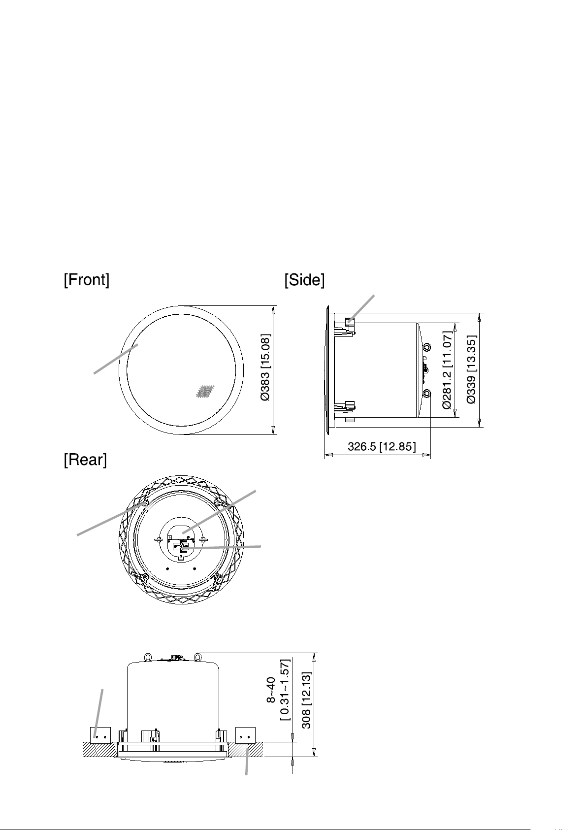
4. NOMENCLATURE AND DIMENSIONS
Unit:mm (inches)
Mounting tab
Front grille
Mounting tab
[ Ceiling mounting ]
Connector cover
Choke bracket
Tile rails
Ceiling tile
3
Page 4
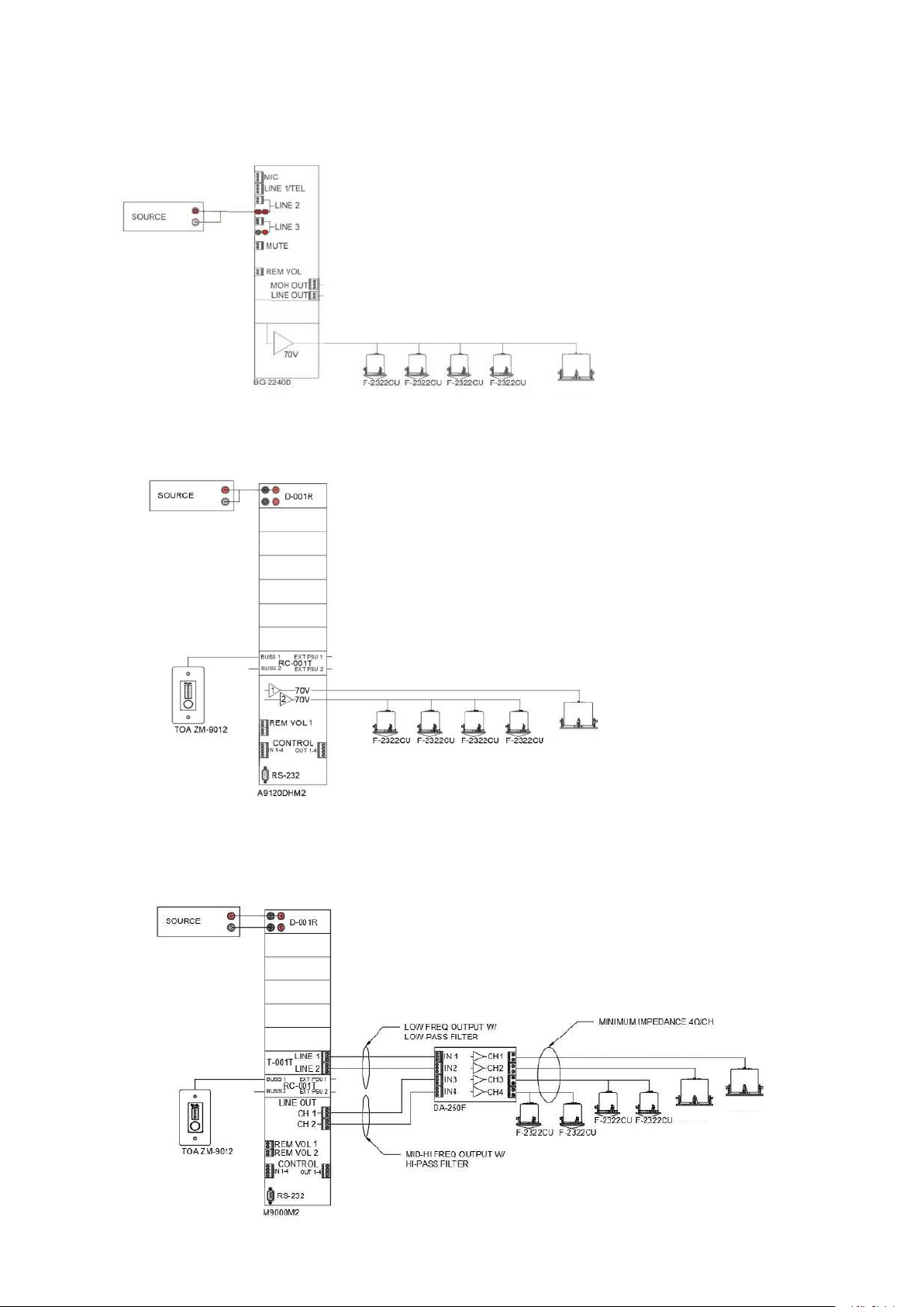
5. SYSTEM EXAMPLE
Example 1- 70V system (one power amplifier)
Example 2- Bi-amplified mono 70V system
FB-3862CU-AM
Example 3- Bi-amplified stereo low impedance system
FB-3862CU-AM
FB-3862CU-AM
FB-3862CU-AM
4
Page 5

6. INSTALLATION
y)
g
[Installation view on Drop Ceilings]
Ceiling
Speaker unit
This speaker must be installed in accordance with local building codes using support and safety cables
to building structure. Failure to properly install these support and safety cables can lead to serious injury
or property. Always use load rated stranded steel cable or equal for support and safety cables. Place
tile rails above the ceiling with the edge triangle parts are catching the T-grids in case the ceiling tile
falls off.
attached
to persons
the supplied
accidentally
Prior to installation- make sure that you have all the components from the carton, plus safety cables
and attachment hardware (not included). There are two separate cartons (shipped together) that contain the
loudspeaker ass embly and mounting accessories-
FB-3862CU-AM loudspeaker with grill
Installation cutout template
Support (“C”)ring
Support rails (qty 2) in a separate box
Tile rail(accessor
T-grid Ceilin
5
Page 6

[Installation Procedures]
g
Step 1. Place the tile that will be used for the speaker finished side down on a clean flat surface. Using the
template, cut a Ø 350mm (13.8”) diameter hole.
Φ350±5
Step 2. Install mounting hardware on the ceiling.
2-1. Place the supplied tile rails on the 2-foot tile as shown below.
2-foot tile
(
13.8"
)
Ceilingtile
Tile rails (accessory)
T-grid
2-2. Place the support r ing over the hole. Insert the tile supports into the C-ring grooves. Adjust the position of
the assembly as required, then fix the tile rails to the support ring using the provided screws.
Tile rails (accessory)
-
C-rin
T-grid
6
Page 7

Step 3. Attach a safety wire from the speaker to the building structure to prevent accidental fall.
g
)
Securely attach one end of the safety wire to the eye bolts located on the top of the speaker, and securely
attach the other end to stable building structure.
Building structure
C-rin
T-grid
Safety wire (not included)
Safety wire (not included)
2-foot tile
Tile rails
Ceiling tile
Speaker unit
7. WIRING
Step 1. Loosen the screws on the choke bracket
to allow the speaker cable to pass through.
Step 2. Loosen the screw on the connector cover plate
and rotate the plate to open.
Step 3. Put the speaker cable through the choke bracket.
Step 4. Detach the removable terminal connector
then wire speaker cable by referring to page 8.
Step 5. Plug the wired removable terminal connector
back into the speaker’s socket.
Loosen four screws
Loosen the left
screw to open the
cover plate
Speaker cable(s
Choke bracket
7
Page 8

Step 6. Retig hten the screws on the choke bracket
p
to fix the speaker cable not to be pulled off.
Step 7. Rotate the cover plate to close and fix it
by retightening the screw.
Retighten the screws
8. CABLE CONNECTION TO TERMINAL CONNECTOR
Recommended cable types
• Solid copper wire: ø1.0 – ø2.0 mm (equivalent to AWG 18 – 12)
• Stranded copper wire: 0.8 – 3.3 mm
Step 1. Loosen the cover mounting screw, and rotate the
Cover plate in the direction indic ated by the
arrow in the figure at right.
2 (equivalent to AWG 18 – 12)
Cover
late
Cover mounting
screw
Speaker unit
Removable
input connector
Step 2. Detac h the removable terminal connector from the
speaker's socket, and loosen the screws of the
terminal to insert wires.
Speaker unit
Step 3. Insert the stripped cable end into the ter minal and tighten the terminal screws with a screwdriver.
[If not bridging] [If bridging]
Note
If not making bridge connections,
be sure to tighten unused terminal
screws to avoid their vibration.
8
Page 9

9. SPEAKER INSTALLATION
Step 1. Remove the front grille.
Turn the mounting tabs out and push them
up towards the grille so that the grille comes off.
Step 2. Insert the speaker through the mounting hole till it
contacts the ceiling panel.
Mounting tab
Mounting
hole
Speaker
unit
Step 3 . Rotate and tighten the mounting tab axis screws (4 places) on the unit clockwise to their full stop in order to
grip the ceiling panel with the mounting tabs.
Mountingtab
Mounting tab
axis screw
Use an electric screwdriver to tighten.
(Tightening torque:6 – 10 kgf·cm)
9
Page 10

Step 4. Set the input power.
Adjust the loudspeaker tap using the 70V range until an acceptable
balance between high/mid loudspeakers and the FB-3862CU-AM is
achieved. (Factory-preset: 30W@70.7
Note
Setting position “Low-Z” can be used in UL1480A Category
UEAY and CAN/CSA C22.2 No.205 Category UEAY7.
CAUTION
Do not use the Low-Z setting with an amplifier that is designed for use with a 70V system. Damage to the
amplifier and/or speaker may occur. If you are installing the FB-3862CU-AM as part of a bi-amplified
system (electronics crossover feeding high/mid and low frequency amplifier channels) with low impedance
amplifiers (4Ω or 8Ω outputs), use the Low-Z
set at 100Hz will help protect the FB-3862CU-AM from extreme low frequencies and provide an
omnidirectional low frequency source.
Step 5. Attach the front grill.
Push the grille up with the edge slides into the slit of the speaker till it gets flat to the speaker frame.
Volt)
direct se
tting. A high pass filter set at 40Hz and low pass filter
10
Page 11

10. REMOVING THE SPEAKER FOR MAINTENANCE
Step 1. Remove the front grill
Find the small gap (see illustration) on the front grill, then use a small flat screwdriver to remove
the front grill.
Caution
The width of the gap is less than 9mm.
Small gap
Step 2. Loosen the mounting tab
Screw
Mounting
tab
Mounting tab
axis screw
Use an electric screwdriver to detach.
Caution
Be sure to set the screwdriver’s torque for under 4 kgf·cm. Failure to do so may cause the screw
cap and the mounting tab to fall off on the rear of ceiling panel.
11
Page 12

11. SPECIFICATIONS
Enclosure Bandpass
Rated Input 60W (70/100V)
Power Handling Capacity 100W RMS 200W Peak (Low-impedance)
Impedance 70V line- 60W/30W/15W/7.5W/3.8W/1.9W with Low Impedance (8Ω)
bypass
Sensitivity 91dB 1W/1m
Frequency Response 45-200 Hz (-10dB)
Speaker Component 8” driver with oiled paper cone and foam surround
Certifications
Mounting Hole 350mm diameter(13.8”)
Input Terminal Phoenix-type with bridging outputs (max 12AWG stranded cable)
Recommended Cable Max 12AWG stranded unshielded twisted pair (jacket per code)
Finish White
Dimensions 383mm diameter x 326.5 mm height
Weight 6.71 kg (14.79 lb)
Included Accessories Steel support ring (C-ring), qty 1
Optional Accessories Support and safety cables (load rated chain or l
Note: The design and specifications are subject to change without notice for improvement
UL2043/UL1480A/CSA C22.2 No. 205, Baffle meets UL 94-V0, RoHS
compliant.
steel support rails, qty 2
speaker hole template, qty 1
operation manual,qty 1
oad rated aircraft cable)
TOA Corporation
133020045500
 Loading...