

Page 1

OPERATING INSTRUCTIONS
SUB-WOOFER SYSTEM FB-100
Please follow the instructions in this manual to obtain optimum results from this unit.
We also recommend that you keep this manual handy for future reference.
TABLE OF CONTENTS
1. SAFETY PRECAUTIONS ............................................................................... 2
2. GENERAL DESCRIPTION ............................................................................ 3
3. FEATURES ......................................................................................................... 3
4. HANDLING PRECAUTIONS ......................................................................... 3
5. NOMENCLATURE ............................................................................................ 3
6. CONNECTIONS ................................................................................................ 4
7. MATCHING TRANSFORMER INSTALLATION ...................................... 4
8. CROSSOVER CONNECTIONS WITH A FULL-RANGE SPEAKER
8.1. Recommended Filters for the FB-100 .............................................................. 5
8.2. Level Balance and Polarity
8.2.1. Level balance adjustment ...................................................................... 6
8.2.2. Polarity adjustment ................................................................................ 6
9. CAUTIONS CONCERNING HIGH-IMPEDANCE APPLICATIONS ... 6
10. INSTALLATION
10.1. Installation Locations ....................................................................................... 7
10.2. Unit Suspension ............................................................................................... 7
11. SPECIFICATIONS ............................................................................................ 8
Page 2
2
When Installing the Unit
• Install the unit only in a location that can
structurally support the weight of the unit and the
mounting bracket. Doing otherwise may result in
the unit falling down and causing personal injury
and/or property damage.
• Do not use other methods than specified to mount
the bracket. Extreme force is applied to the unit
and the unit could fall off, possibly resulting in
personal injuries.
• Use proper nuts and bolts when hanging the
speaker. If improper nuts and bolts are used, the
speaker could fall off, resulting in personal injury.
• Tighten each nut and bolt securely. Ensure that the
bracket has no loose joints after installation to
prevent accidents that could result in personal
injury.
When the Unit is in Use
• Do not operate the unit for an extended period of
time with the sound distorting. This is an indication
of a malfunction, which in turn can cause heat to
generate and result in a fire.
Indicates a potentially hazardous situation which, if mishandled, could
result in death or serious personal injury.
Indicates a potentially hazardous situation which, if mishandled, could
result in moderate or minor personal injury, and/or property damage.
WARNING
1. SAFETY PRECAUTIONS
• Be sure to read the instructions in this section carefully before use.
• Make sure to observe the instructions in this manual as the conventions of safety symbols and messages
regarded as very important precautions are included.
• We also recommend you keep this instruction manual handy for future reference.
Safety Symbol and Message Conventions
Safety symbols and messages described below are used in this manual to prevent bodily injury and property
damage which could result from mishandling. Before operating your product, read this manual first and
understand the safety symbols and messages so you are thoroughly aware of the potential safety hazards.
CAUTION
WARNING
CAUTION
Page 3
3
2. GENERAL DESCRIPTION
The TOA FB-100 is a high-power sub-woofer system employing a 25 cm speaker unit designed to withstand
large, low-frequency voice-coil movement. Although small in size, the FB-100 provides clear super-low
frequency sound reproduction thanks to its Acoustic Super Woofer enclosure construction.
3. FEATURES
• A large, 120 mm-diameter ferrite magnet, a long, 50 mm-diameter voice coil, an aluminum bobbin, a nonpressed paper cone, and a large-diameter damper combine to permit large voice coil movement at high
power input.
• The Acoustic Super Woofer system enclosure creates an acoustic band-pass filter that reproduces superlow frequencies down to 35 Hz and realizes slow-slope phase characteristics.
• The speaker can be converted to high-impedance applications with the addition of the optional MT-S0610
matching transformer.
• The urethane-painted enclosure is made of Medium Density Fiberboard (MDF) and can be easily repainted.
• Six external mounting screws are positioned along the sides of the enclosure to facilitate cable-suspended
installations.
• The unit's removable top panel facilitates maintenance work after installation.
4. HANDLING PRECAUTIONS
No anti-magnetic provisions have been made for the FB-100 speaker. Therefore, take care to keep the unit
sufficiently away from televisions, monitors or computer-related equipment.
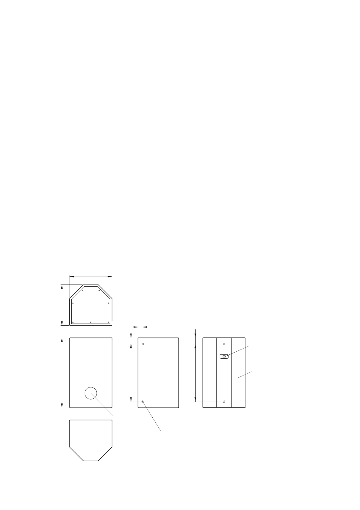
5. NOMENCLATURE
[Top]
[Front]
[Bottom]
[Rear]
[Side]
354
40
51480
51480
582 340
Port
Detachable input connector
Enclosure
Mounting screw
(W3/8, 6 places)
Unit: mm
Page 4

4
6. CONNECTIONS
Note: The FB-100's input connector is of detachable type.
Step 1. Detach the input connector from the
connector socket.
Step 2. Using a screwdriver, loosen the screws of
the terminals to use. Connect stripped cable
ends to the terminals, then retighten the
terminal screws.
Tips
• Usable cable: Solid cable or stranded cable (0.2
mm2- 2.5 mm2) (Corresponding to
AWG No. 24 - 14)
• Strip the insulation back about 5 mm from the cable
ends.
[When bridging no terminals]
[When bridging terminals]
Step 3. Insert the input connector into the unit.
7. MATCHING TRANSFORMER INSTALLATION
An optional MT-S0601 matching transformer can be installed in the FB-100 speaker.
Step 1. Remove 7 screws to detach the enclosure
top panel.
Step 2. Remove 2 transformer mounting screws
located close to the connector circuit board.
Using the 2 screws, mount the MT-S0601
transformer with its connection lug
(impedance tap) side up.
Detachable input
connector
From amplifier
To next sub-woofer
system
Note: Tighten the screws of idle
terminals as well to
prevent resonance noise.
MT-S0601
Transformer mounting
screw
Page 5

5
Step 3. Disconnect the junction connector of a lead
wire coming from the connector circuit
board. (Widen the lock tab to pull the
connector.)
Step 4. Connect the MT-S0601's two connectors to
the junction connectors disconnected in Step
3.
Step 5. Connect the speaker input cable to the
desired transformer lug to set the
impedance.
Step 6. Replace the top panel and retighten the 7
screws.
Step 7. Affix the impedance label supplied with the
MT-S0601 to over the FB-100's nameplate
as shown below to indicate the selected
transformer impedance.
8. CROSSOVER CONNECTIONS WITH A FULL-RANGE SPEAKER
8.1. Recommended Filters for the FB-100
• Because the FB-100's enclosure construction
is designed to create an acoustic band-pass
filter, the mid and high frequency audio
ranges are cut even if the input signal band is
not limited with a low-pass filter. Therefore,
the FB-100 functions as a sub-woofer with no
filtering.
• The speaker driving efficiency can be
increased by inserting a low-pass filter before
the power amplifier to cut out the mid and
high frequency components of the input
signal to the sub-woofer.
• The following filter settings are recommended when using a
digital signal processor for the FB-100's signal system:
High-pass filter (–12 dB/oct):
Cut-off frequency = 40 Hz, Q = 1.0
Low-pass filter (–12 dB/oct):
Cut-off frequency = 100 Hz, Q = 1.0
Red White
MT-S0601
Impedance label
Nameplate
FB-100's cross section
Frequency-to-Output sound pressure level relationship
[dB]
(1 W 1 m, 1/2 free sound field)
110
100
90
80
70
60
50
20
50 100 500 1k 5k 10k 20k
[Hz]
[dB]
+20
+10
-
-
-
-
Frequency-to-Gain relationship
0
10
20
30
40
20
50 100 500 1k 5k 10k 20k
[Hz]
Page 6

6
8.2. Level Balance and Polarity
When using the FB-100 in combination with TOA's F or H Series Full-Range Speakers, adjust their level
balance or polarity depending on the conditions of the installation location.
8.2.1. Level balance adjustment
Adjust the level of the sub-woofer or full-range speaker depending on the number of units to be installed or
installation conditions.
8.2.2. Polarity adjustment
• Acoustic energy increases at the crossover band for the sub-woofer and full-range speaker if the two
speakers are in phase with each other, and decreases if out of phase. Because the phase characteristics of
both the sub-woofer and the full-range speaker vary continuously depending on frequency, simply matching
the connector polarities of the sub-woofer is not always the best procedure.
• To confirm how much the acoustic energy increases or decreases, reverse the polarity of the sub-woofer's
"+" and "–" connectors and select the connection polarity that results in the largest output of acoustic energy.
(The use of a real-time spectrum analyzer to check the degree of energy increase is highly recommended.)
9. CAUTIONS CONCERNING HIGH-IMPEDANCE APPLICATIONS
To avoid damaging the FB-100 speaker in high-impedance applications (with the MT-S0601 matching
transformer installed), be sure to observe the following conditions.
1. Do not limit the input signal band using such devices as a low-pass filter, but instead drive the speaker with
the full-range signal.
2. Use a high-impedance amplifier with a power rating higher than the wattage tap selected on the matching
transformer.
Tip
There is a low-frequency threshold for both the speaker matching transformer and the high-impedance
amplifier output transformer.
[Matching transformer low-frequency threshold]
If a signal with the frequencies lower than the low-frequency threshold is applied at rated power, the
transformer's primary impedance (input impedance) decreases abruptly due to core magnetic saturation. With
the MT-S0601, the impedance begins to decrease at approximately 40 Hz for the rated input power of 60 W,
and is almost halved at 30 Hz. If the speaker is used under this condition, an increased load is put on the
power amplifier as well as the matching transformer, causing potential equipment damage.
The low-frequency threshold varies depending on the selected transformer tap, and the smaller the tapselected wattage, the lower the threshold.
[High-impedance amplifier low-frequency threshold]
When a full-range signal (not band-limited) is applied, the amplifier is not adversely affected.
However, if the signal is band-limited with a low-pass filter and driven with rated power, an increased load is
put on the output stage, causing potential amplifier damage.
Page 7

7
10. INSTALLATION
10.1. Installation Locations
By installing the FB-100 speaker close to the ceiling, wall or floor, the speaker's sound energy radiation
efficiency can be increased.
Note
Do not block the opening of a port.
10.2. Unit Suspension
Using six mounting screws provided on the FB-100 in
conjunction with eyebolts, the FB-100 can be hung as illustrated.
Note
Ensure that the speaker is fixed or hung at 4 places or more
when using the mounting screws to fix or hang the unit.
4π space: +0 dB (free sound field)
π space: +12 dB (1/4 free sound field)
π/2 space: +18 dB (1/8 free sound field)
2π space: +6 dB (1/2 free sound field)
Eyebolt
Page 8

11. SPECIFICATIONS
Note: The unit's specifications and external design are subject to change without notice for
improvement.
• Optional equipment
Matching transformer MT-S0601 (rated at 60 W)
Enclosure Acoustic Super Woofer system
Power Handling Capacity Continuous program: 450 W
Continuous pink noise:150 W (40 – 200 Hz, 24 hours)
Rated Impedance 8 Ω
Output Sound Pressure 94 dB (1 W, 1 m), installation in 1/2 free sound field
Level 88 dB (1 W, 1 m), installation in free sound field
Frequency Response 35 – 160 Hz (–10 dB, installation in 1/2 free sound field
Internal Speaker 25 cm cone type
Input Terminals Detachable screw terminals, (+)/(–): 2 each (for bridge connection)
Usable Cable Solid or twisted cable: 0.2 - 2.5 mm2(corresponding to AWG24-14)
Finish Urethane-painted Medium Density Fiberboard (MDF), black
Dimensions 345 (w) x 582 (h) x 340 (d) mm (projections excluded)
Weight 16 kg
133-01-424-4B
URL: http://www.toa.jp/
Traceability Information for Europe (EMC directive 2004/108/EC)
Manufacturer:
TOA Corporation
7-2-1, Minatojima Nakamachi, Chuo-ku, Kobe, Hyogo,
Japan
Authorized representative:
TOA Electronics Europe GmbH
Suederstrasse 282, 20537 Hamburg,
Germany
 Loading...