

Page 1
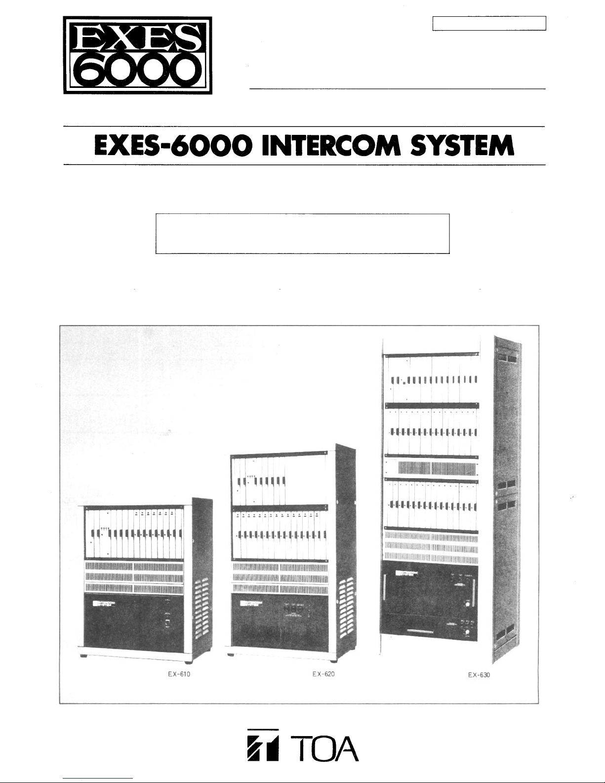
EXES-6000
For
INTERCOM SYSTEM
Fully Electronic Exchange
EX-610/620/630
INSTALLATION HAND BOOK
EX-610/620/630
Page 2

WARNING: (For U.S.A. only)
This equipment generates, uses, and can radiate radio frequency energy
and if not installed and used in accordance with the instructions manual,
may cause interference to radio communications. It has been tested and
found
to
comply
with
the
limits
for a
Class A computing
device
pursuant to Subpart J of Part 15 of FCC Rules, which are designed to
provide reasonable protection such interference when operated in a
commercial environment.
Operation of this equipment in a residential area is likely to cause
interference in which case the user at his own expense will be required
to take whatever measures may be required to correct the interference.
Page 3

CONTENTS
INTRODUCTION TO THE INSTALLATION MANUAL FOR EXES-6000
— P AR T 1. OUTLINES OF EXES-6000 SYSTEM AND RELATED EQUIPMENT —
1. Description and Features
1-1 System
1-2 Exchanges (EX-610/620/630)
1-3 Stations
1-4 Terminal Boards (BX-610/620)
1-5 Junction Cables (YR-810/801)
2. Example of Exchange Mounted on Intercom Cabinet Rack
3. Recommendable Example of Exchange Mounted on Amplifier Cabinet Rack
4. Specifications Related to Installation
5. Functions of Units Mounted on Exchanges EX-610/620/630
5-1 CP (Central Processing Unit)
5-2 OC (Output Control Unit) .
5-3 HC (Highway Control Unit)
5-4 SG (Signal Generating & Distributing Unit)
5-5 DL (Duplex Link Unit) . .
5-6 CL (Conference Link Unit)
5-7 LM (Line MODEM Unit) .
5-8 SI (Speech Interface Unit)
5-9 PI (Paging Interface Unit)
5-10 SA (Station Paging Assignment Unit]
5-11 Tl (Tie-line Interface Unit)
5-12 DS (Power Supply Unit) . .
5-13 BC (Battery Case) . . . . .
page
1
2
2
2
2
2
3
5
5
6
6
6
7
8
8
8
8
8
8
8
8
8
— PART 2. INSTALLATION OF EXES-6000 SYSTEM —
6. Installation of the EXES-6000 System
6-1 Exchanges
6-2 Stations . .
6-3 Accessories
7. Cable Installation
7-1 Type of Cables
7-2 Core Diameter versus Transmission Distance
7-3 Wiring
1. General Information
2. Spacing
3. Piping .
8. Connection of Equipments
8-1 Connection of Power Supply
8-2 Connection between the Exchange and the Terminal Board (BX-610 or BX-620) . .
8-3 Connection of the Terminal Board (BX-610 or BX-620) to the Main Terminal Board
8-4 Connection of the Station Plug to the Exchange Jack
8-5 Connection of Stations
9. Connection and Adjustment of Equipment
9-1 Connection of the Speaker Station (Simplified Paging)
9-2 Paging Connection
1. PA Paging
2.1 Station Paging (for EX-610/620)
2.2 Station Paging (for EX-630) .
9-3 Calling Tone Modifications. .....
9-4 Caution for Conference Unit Usage
9-5 Remarks on Indication and Control
9-6 Connection of Station for Emergency Paging . . .
9-7 Method to Establish Press-to-talk Control Function
9-8 Connection of PI-62 to call a pager receiver
9-9 BGM equipment connection
10. Inspection
10-1 Check when Power is Switched On
10-2 Speech and Function Tests
10-3 System Check Flow Chart
10-4 Simple troubleshooting
9
9
9
9
10
10
11
11
11
12
16
18
19
20
21
22
23
27
29
29
29
29
29
29
30
31
31
32
33
Page 4

INTRODUCTION TO THE INSTALLATION MANUAL FOR EXES-6000
This manual forms part of the Installation Manual for INTERCOM SYSTEM EXES-6000.
The EXES-6000 permits various functions besides normal speech by programming or con-
necting optional equipment according to your specific needs. Correct operation of these
additional functions is not performed by simply connecting the additional equipments/
devices. Provision of such additional function requires the following:
(1) Connection of the additional equipment, as required.
(2) Selection of functions which satisfy your needs and setting up these functions in the
respective equipment.
This "Installation Handbook of Exchanges EX-610/620/630 for EXES-6000 System"
contains technical instructions as to connection of exchange, etc, mentioned in the above
Paragraph (1). In addition to this, the proper installation of the system necessitates the
other installation manuals dealing with the selection of the function and its programming
referred to in the above Paragraph (2).
– 1 –
Page 5

PART1. OUTLINES OF EXES-6000 SYSTEM AND RELATED EQUIPMENT
1. Description and Features
1-1 System
Since the EXES-6000 System is a fully electronic intercom
system, it has the following features that surpass conventional
mechanical systems.
1. All components of the exchange are designed according to the
modular concept. This results in a sizable reduction in the
number of procedures required to install the system.
2. The exchange and terminal boards (BX-610/620) are designed
as separate units, allowing independent inspection of the wiring
and the exchange.
3. The wiring for each station is a non-polar 2-wire system which
uses a minimum
number
of
connecting
to
ease
wiring.
1-2 Exchanges EX-610 (64 stations)/EX-620 (128
stations)/EX-630 (256 stations)
The features of the exchange of the Toa EXES-6000 Intercom
Syste m are as follows:
1. All exchange are of modulor constructions. This results in a great
increase in ease and speed of system installation.
2. Extensive incorporation of ICs makes each exchange efficient
and space-saving as well as allows quieter operation than conventional intercom system.
1-3 Stations
The stations of the Toa Intercom EXES-6000 have the following
features:
1.
Each
station
is
connection to cables.
provided
2. Wiring from the exchange to each station is the non-polar 2-wire
system. The fact that only 2 wires are necessary makes installation easier, and with a 2-Pin jack (YC-601 or YC-603) at the end
of each cable, connection can be quickly made with a screwdriver.
3. There are eleven types of stations available for selection: desk-
top type, flush-mount type and desk/surface-mount type, etc.
with a 2-Pin
plug
(YC-602)
for
easy
1-4 Terminal Boards (BX-610/620)
The terminal boards BX-610/620 connect the line between the
exchange and the station. Compact and easy to connect, this
terminal board saves space and ensures simple disconnection of any
station line from the exchange when inspection is necessary. One
terminal board BX-610 or BX-620 can connect a maximum of 64
stations (EX-610) or 128 stations (EX-620) to the exchange all-call
plus 15 paging zones and 8 tie-line links. The exchange and the
terminal board are connected by junction cable YR-810 (2-wire)
for stations and YR-801 (4-wire) for paging and tie-line links.
To connect the station line to the terminal board, clip terminals are
provided which allow ensure simple connection without soldering.
For future system expansion or modification, the collective terminal
board to be described later on. (See page 12) This terminal is part of
the exchange.
1-5 Junction Cables ( Y R -810/801)
The YR-810 or YR-801 junction cable connects the exchange to
the terminal board BX-610 or BX-620. A single line of this junction
cable is capable of connecting the exchange to 8 stations (YR-81 0)
or to 8 paging zones (YR-801) or to 8 tie-line links (YR-801)
through the terminal board BX-610 or BX-620. Both cable ends are
equipped with multi-pole connectors which can easily plugged into
the exchange or the terminal board BX-610 or 620. Refer to the
drawing which appears in the Cable Installation and Connection
seciton of this manual for the right direction and order of cable
connections.
– 2 –
Page 6

2. Example of Exchange Mounted on Intercom Cabinet Rack
(Including All-Call Paging and 15 Individual Zone Paging units and one Data Transmitting unit)
Exchange EX-620 (for 128 stations)
Exchange EX-610 (for 64 stations)
Central Processing Unit CP-66.
Output Control Unit OC-62
Highway Control Unit HC-62
Signal Generating and Distributing Unit SG-62
Conference Link Unit CL-62A (In this location, DL-62A is
also mountable.)
Duplex Link Unit DL-62A (CL-62A may be inserted into these
positions instead of DL-62A.).
Line Modem Unit LM-62B (LM-65, Line Modem Unit with
BGM function, may be inserted into these positions instead of
LM-62B).
Paging Interface Unit PI-62 (Type 2) (In t his location, LM-62B
or Tie-line unit TI-62 is also mountable.) (Zone 8~15 without
All-Call Paging)
Paging Interface Unit PI -62 (Typ e 1) (In this location, LM-62B
is also mountable.) (Zone 1~7 wit h All-Call Paging)
Perforated Panel PF-023A*
Data Transmitting Unit DT-E60 ( In the standard system, Perforated Panel PF-013A should come in this position.)* Junction
Cable YR-80 6 (Cable length: 1000mm) (YR-802 Cable length:
400mm) is not available.)
Note.*
The Exchange Cabinet Rack CR-610 or CR-620 includes
Perforated Panels PF-013A and PF-023A.
Power Supply Unit DS-620
Power Switch
AC Fuse 3A(110V/120V), 1.5A(220V/240V)
DC Fuse 20A(for use of 65 ~ 128 stations)
Battery Fuse 5A
Exchange Cabinet Rac k CR-620
Exchange Frame FR-620A
Power Supply Unit DS-610
Power Indication Lamp
Battery Power Indication Lamp
Buzzer Stop Switch
Exchange Cabinet Rac k CR-610
Exchange Frame FR-610A
Speech Interface Unit SI-62 (LM-62B may be
inserted into this position instead.).
– 3 –
Page 7
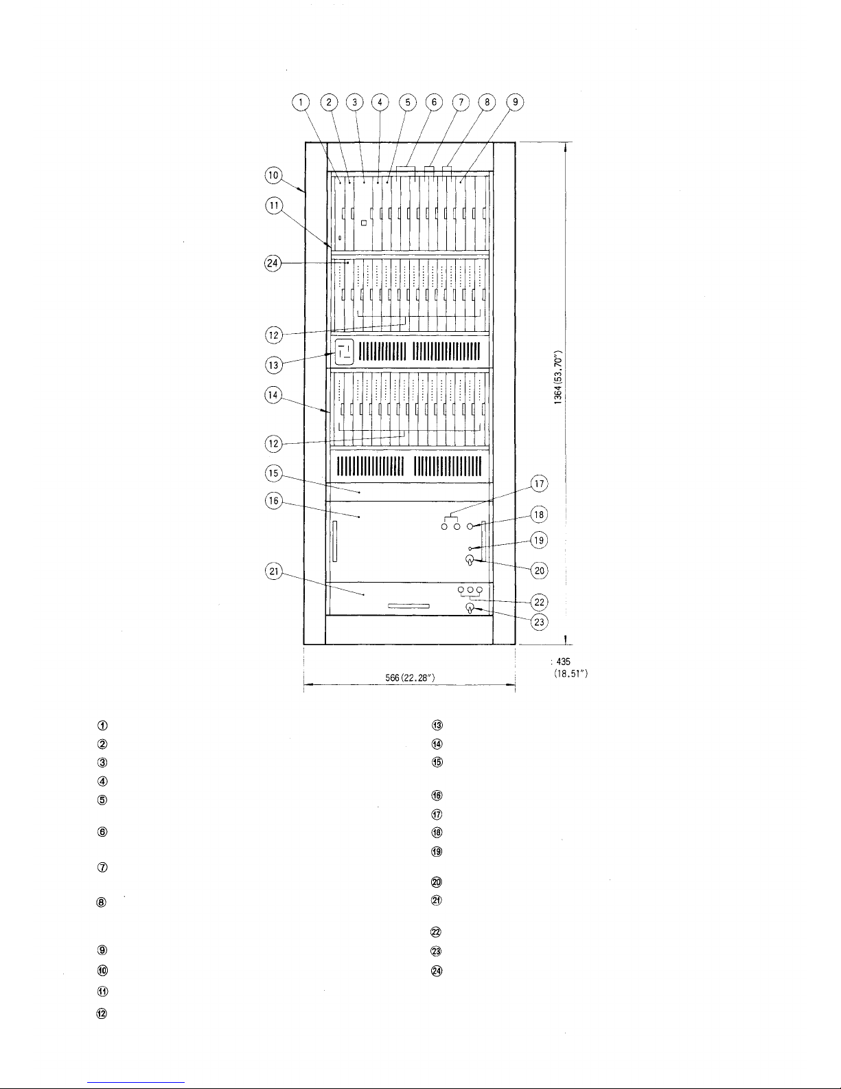
Exchange EX-630 (for 256 stations)
Central Processing Unit CP-66.
Output Contro l Unit OC-62
Highway Control Unit HC-64
Signal Generating and Distributing Unit SG-62
Conference Link Unit CL-62A (In this location, DL-62A is
also mountable.)
Duplex Link Unit DL-62A (CL-62A may be inserted into thes e
positions instead of DL-62A.)
Paging Interface Unit PI-62 (Type 1 in the left position, type 2
in the right position).
Tie-line Interface Unit TI-62 (In this location, Pl-62's are also
mountable. Type 3 in the left position, type 4 in the right
position)
Station Paging Assignment Unit SA-64
Cabinet Rack CR-271
Exchange Frame FR-630A
Line Modern Unit LM-62B (LM-65, Line Modem Unit with
BGM function, may be inserted into these positions instead of
LM-62B.)
Depth
Jack for Programming Station
Extention Frame FR-631A
Data Transmitting Unit DT-E60 (When this unit is not used,
mount Perforated Panel PF-013A in this place.)
Power Supply Unit DS-630
DC Fuse 20A (for use of 129 ~ 256 stations)
AC Fuse 10A (110V/120V), 5A (220V/240V)
Power Indication LED lamp (green for AC operation,
red for battery operation)
Power Switch
Battery
Case
BC-630
(When
this
unit
is not
used,
the Perforated Panel PF-023A in th is place.)
Battery Fuse 10A
Battery Power Switch
mount
Speech Interface Unit SI-62 (LM-62B may be inserted into this
position instead.)
– 4 –
Page 8
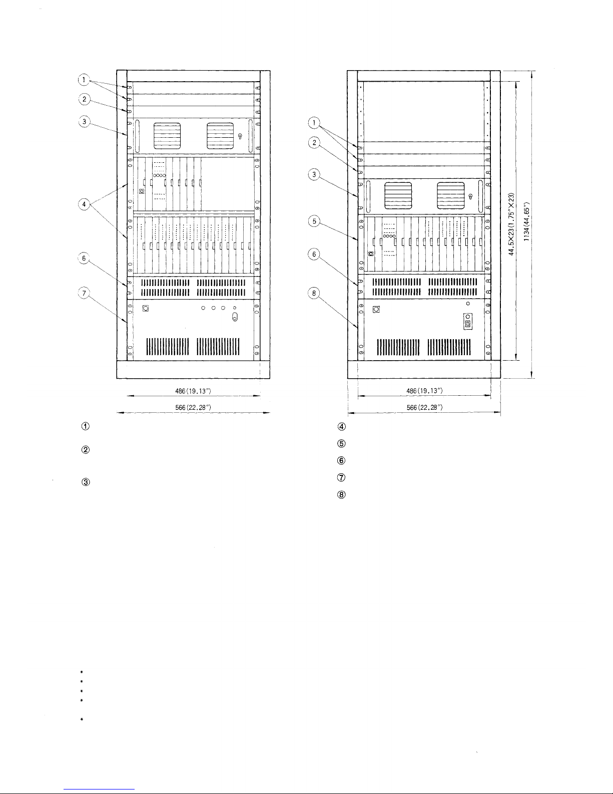
3. Recommendable Example of Exchange Mounted on Amplifier Cabinet Ra c k
Exchange EX-620 (for 128 stations)
Exchange EX-610 (for 64 stations)
Data Transmitting Unit DT-E60
Junction Cable YR-803 (for additional DT-E60)
Data Transmitting Unit DT-E60
Junction Cable YR-802 (Cable length: 400mm) or YR-806
(Cable length: 1000mm)
Blower Panel BP-031A (Do not substitute perforated panel for
this)
4. Specifications Related to Installation
4-1 Exchange
1) Wiring
Non-polar one twisted pair
Loop
Resistance:
Impedance: 600 ohms , balanced
Cable length: max. 1.0km (0.4mm dia.)
2) Power Sources (DS-610/620/630)
AC Mains (110, 120, 220, 240V) ± 10% 50/60Hz 24V DC
3) Rated Power Consumption
EX-610 130W (No link occupied) 300W (Max.)
EX-620 210W (No link occupied) 500W (Max.)
EX-630 410W (No link occupied) 1kw (Max.)
4) Battery for System Back-up on AC Power Failure (Option)
Type Sealed type Ni-Cd battery NDC-2435
Voltage 24V
Capacity 3500mAh
Charge System
Service Hours
EX-610: Approx. 2 hrs.
(2 x NDC-2435 necessary per system)
EX-620: Approx. 1.5 hrs.
(3 x NDC-2435 necessary per system)
EX-630: Approx. 1.5 hrs.
300
ohms,
or
less
max. 2.5km (0.65mm dia.)
max. 3.5km (0.9mm dia.)
Trickle Charging, approx. 1/40CA (20°C)
(3 x NDC-2460 necessary per system)
Exchange EX-620 (Frame FR-620A and necessary Units)
Exchange EX-610 (Frame FR-610A and necessary Units)
Perforated Panel PF-023A
Power Supply Unit DS-620
Power Supply Unit DS-610
5) Ambient Temperature
0~40°C(+32° ~+104°F)
6) Dimensions EX-610: 510(W) x 656(H) x 325(D)mm
(20.08" x 25.83" x 12.80")
EX-620: 510(W) x 878(H) x 325(D)mm
(20.08" x 34.57" x 12.80")
EX-630: 566(W) x 1364(H) x 435(D)mm
(22.28" x 53.70" x 17.13")
7) Weight EX-610: 45kg (99.1 IDS.) without battery
EX-620 : 57k g (125.63 Ibs.) without battery
EX-630: 109kg (240.30 Ibs.) without battery
Caution. Both top and side panels are perforated for ventiation
(EX-610/620). Do not place things on the top panel or
close to the side panels. (Intercom cabinet rack)
For maintenance works, allow much space between the
wal l and th e cabinet rack.
4-2 Station
Ambient Temperature
: 0° ~ +60° C (+32° ~ +140°F) (Except HF-640S)
: -10° ~ +60°C (+14° ~ +140°F) (Door Station HF-640S)
Permissible Loop Resistance: 300 ohms
Input/Output Impedance : 600 ohms (balanced)
Note. For details such as functions, dimensions and specifications,
refer to Spec. Sheet f or each equipment.
– 5 –
Page 9
5. Functions of Units Mounted on Exchanges EX-610/EX-620/EX-630
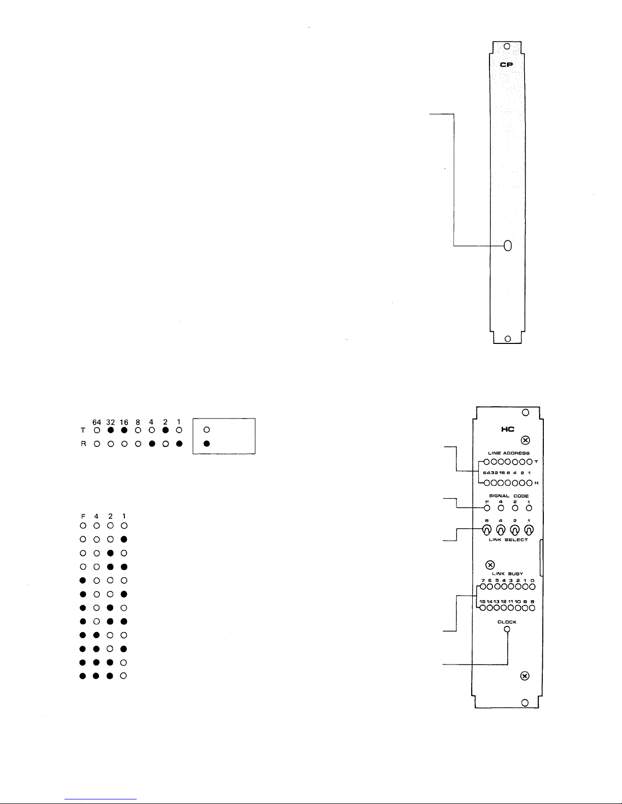
5-1 CP (Central Processing Unit)
Function: Reads out the exchange procedures written into the
5-2 OC (Output Cont rol Unit)
Function: Stores temporarily the output data from the CP unit
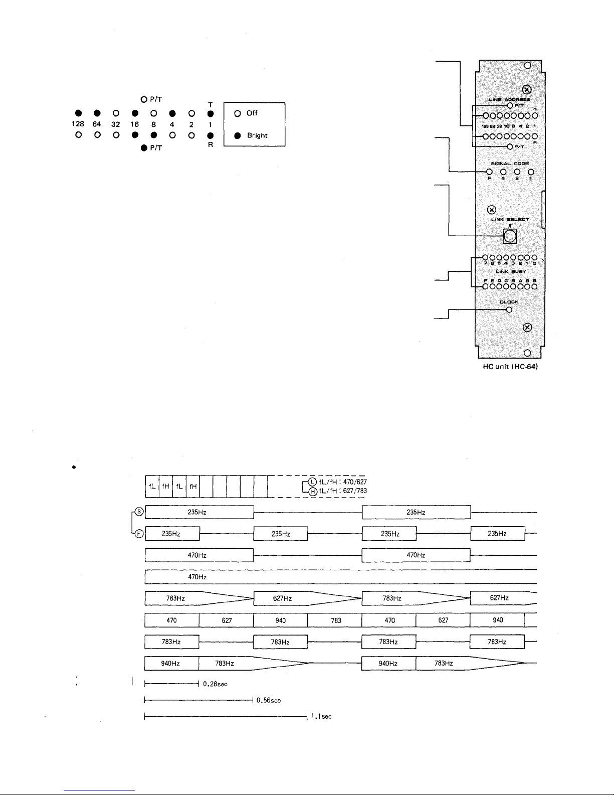
5-3 HC (Highway Control Unit HC-62
..... EX-610/620; HC-64..... EX-630)
Function: Turns on and off the time sharing switches at the LM,
memory ( ROM) and collates the data from stations for
traffic processing.
and distributes them to each unit.
DLand SG units according to instructions received from
the CP unit. The link busy indicator lamps on the front
panel dis pla y th e number of th e l in ks in us e.
PROGRAM SWITCH for #200
Programming
Set this to "ON" position only
at time of initial programming
of the exchange and registration
of functions. In this case,
station No.200 is "programming
station" but becomes a normal
station when switch is placed in
"OFF" position.
PROGRAM
ON
OFF
CP unit
(Example for HC-62)
LINE ADDRESS
Calling Station (T): No. 250
(200+32+16+2 = 250)
Called Station (R ) : No. 205
(200+4+1 = 205)
SIGNAL CODE
During Conversation
Press-to-talk (R -» T)
Press-to-talk (T-> R)
OFF duration on T & R
Calling
Privacy/Disconnected
Busy
Dialing
Zone paging
All call
Priority/Executive priority
Registration/Call holding/Mic-off
TONE AND
SPEECH MODE
Off
Bright
LINE ADDRESS Lamp
These lamps display the station
numbers (Binary number) using the
selected link (T: Calling station, R:
Called station)
SIGNAL CODE Lamp
These lamps display the code of
signal tone being used in the
selected link.
LINK SELECT Switch
The switch position is to be selected
in accordance with the number of
links in use. The line address and
the signal code of the link in use
are then displayed by the lamps.
Note: Operate these switches using
the binary notation.
LINK BUSY Lamp
These lamps display the number of
the links in use.
CLOCK Lamp
This lamp, when on, indicates
that the control signal for the
time sharing switch is being
transmitted normally.
HC uni t (HC-62)
– 6 –
Page 10
(Example for HC-64)
LIN E ADDRESS
LINE ADDRESS Lamp
These lamps display the station
numbers (Binary number) using the
selected link (T: Calling station,
R: Called station). The P/T lamps
when a paging or tie-line call is
made.
These lamps display the code of
signal tone being used in the select-
Calling Station ( T ): No. 413
(200+ 128 + 64+ 16 + 4 + 1 = 41 3)
Called Station ( R ) : paging No. 25
(16 + 8 + 1 = 25)
ed link.
The switch position is to be selected
in accordance with the number of
links in use. The line address and
the signal code of the link in use
are then displayed by the lamps.
Note: Operate this switch using the
hexadecimal notation.
These lamps display the number of
the links in use.
Indicates that the control signal for
the time sharing switch is being
transmitted normally.
5-4 SG (Signal Generating and Distributing Unit)
Function: Composed of 8 kinds of signal generators (calling, privacy/disconnected,
Tone of SG Unit
busy, dialing, zone paging, all call, priority/executive priority, registration
confirmation/call holding/mic-off) and distributors.
This unit distributes under HC control the required signal tones to each
individual link.
SIG NA L CODE Lamp
LINK SELECT Switch
LINK BUSY Lamp
CLOCK Lamp
Calling tone
Privacy tone
Busy tone
Dialing tone
Zone Paging
All-Call Paging
Priority tone
Holding tone
Registration
confirmation
(
tone
)
– 7 –
Page 11
5-5 DL (Duplex Link Unit)
Function: Operates under the control of the HC unit to connect or disconnect the
individual links for conversation between two stations, changing over
from the hands-free conversation to the full duplex conversation mode,
or
vice
versa.
be mounted in t he EX-610 and up to 4 in the EX-620/630.
One DL
unit
is
provided
with 4 links.
Up to 3 DL
units
can
5-6 CL (Conference Link Unit)
Function: Operates under the control of the HC unit to connect or disconnect the
links for conversation among up to 4 parties and conversation between 2
parties. One CL u n it i s provided with 1 conference link and 2 speech links.
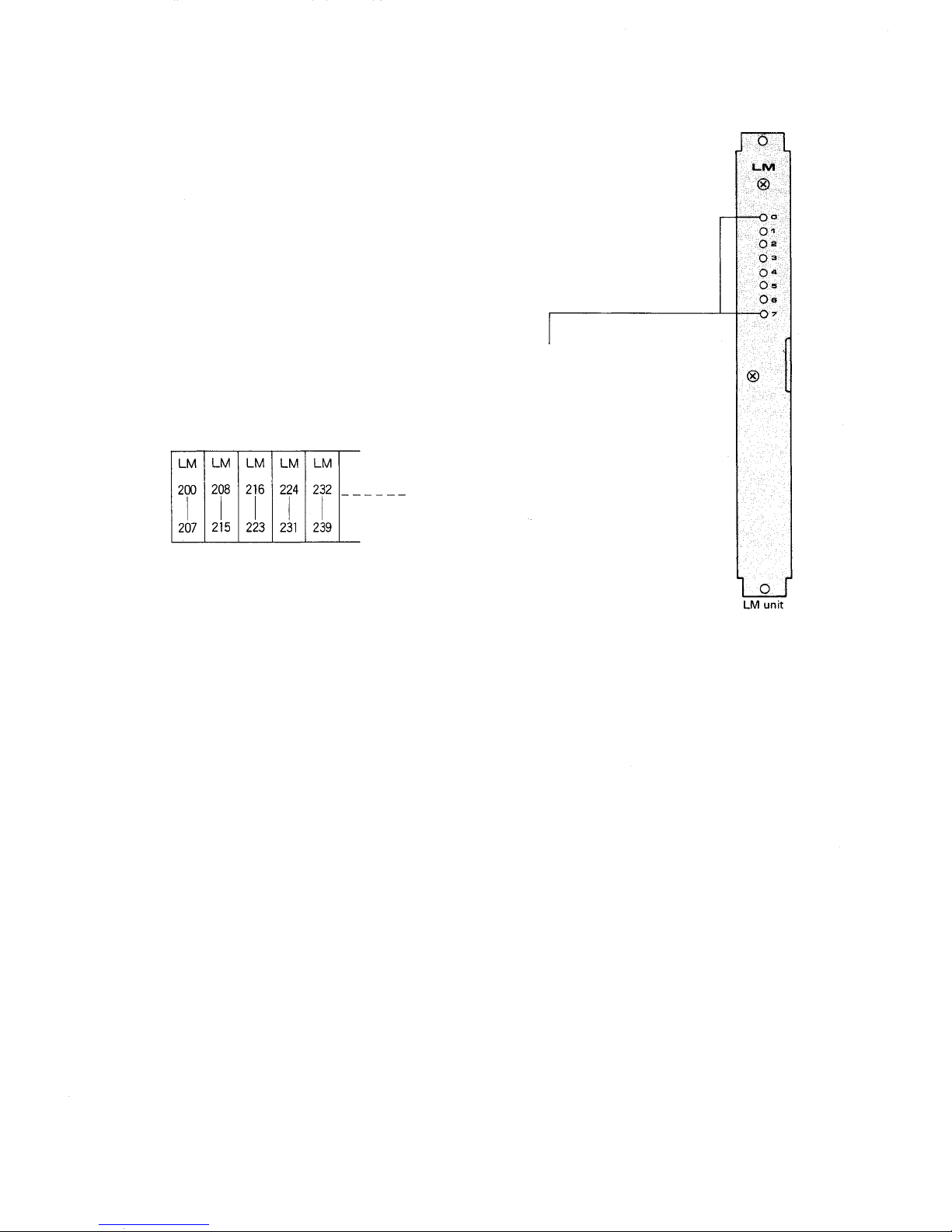
5-7 LM (Line MODEM Uni t)
Function: Is composed of a modulator to transmit signals from
the station to the speech link, a demodulator to send
out signals from the speech link to the station, a dial
receiver and a scanning circuit that scans the station
"Privacy ON/OFF" conditions and "Handset ON/ O FF "
conditions. Up to 8 stations can be connected per LM
Unit.
Station number lamp
Each lamp varies its brightness to in-
dicate the condition of the station. The
relation between brightness and line
status is as follows:
Bright: Exchange and station are con-
Off: Exchange and station are not
Extremely bright (yellow):
nected properly.
connected.
Short circuited between paired
lines.
Arrangement of the LMs with individual ranges for the
station numbers covered (from left to right) is shown here.
5-8 SI (Speech Interface Unit)
Function: Connects to the SM-600 Speech Message Device to
send or receive a voice signal.
5-9 PI (Paging Interface Unit)
Function: Provides PA paging and stati on paging. It sends out both
paging voice signals and relay make signals for power
remote control of the PA amplifier. It also delivers the
serial output for radio pagers. The PA paging si gna l goes
out through the assigned YR-801 cable to terminal P1
or P2 of the BX-610/620 terminal boards.
5- 1 0 SA (Station Paging Assignment Unit)
Function: Distributes each of paging outputs to each LM unit.
This unit cannot be used for EX-610/620.
5-11 T l (Tie-line Interface Unit)
Function: When 2 or 3 exchanges are tie-line connected, this units
transmits and receives the audio signals and dial data
between the exchanges.
5-12 DS (Power Supply Unit)
1. DS-610 (for 64 stations)
An exclusive power supply unit for the EX-610 exchange.
This unit cannot be used in the system for more than 64 stations.
2. DS-620 (for 128 stations)
An exclusive power supply unit for the EX-620 exchange and can
also be used for the EX-610 exchange.
3. DS-630 (for 256 stations)
An exclusive power supply unit for EX-630 exchange.
5-13 BC (Battery Case)
An exclusive battery case for EX-630.
Accomodates three of Ni-Cd batteries (Sealed type, NDC-2460).
The charger circuit is incorporated in DS-630.
– 8 –
Page 12

PART2. INSTALLATION OF EXES-6000 SYSTEM
6. Installation of the EXES-6000 System
6-1 Exchanges
Pay particular attention to the following points du ring installation
of the exchange:
The layout should allow easy servicing and inspection.
The exchange is compact and lightweight; however it is important to ascertain the strength of the floor or wall on which it will
be placed.
The exchange should be grounded. When it is used in combination with other systems, for example, a PA system, the exchange
should be connected to the other components for common
grounding.
Choose a low "source noise" AC power supply f or th e exchange.
Line noise can downgrade speech quality.
Be sure to provide a power outlet for the exchange and have its
capacity checked. A capacity of 500 watts is su fficient.
Plan the layout so that the terminal board BX-610 or BX-620
can be installed near the exchange.
System should include a surge protector.
This high performance exchange is compact as well as quiet, and can
be easily installed almost anywhere. Areas described below, however,
should be strictly avoided.
An area where it will obstruct traffic, for example, an indoor
hallway or near the entrance or exit of a room.
An area where it will be exposed to fire, heat or direct sunlight
(suitable ambient temperature is 0° ~ +40°C (+32° ~ +104°F)).
A dusty area (where there is metal dust or dirt).
Near a storage place for chemicals, oil, etc.
An area susceptible to vibration.
Near high-voltage equipment.
In a strong electric field.
Near equipment vulnerable to the influence of an electric field.
6-3 Accessories
The terminal board BX-610 or BX-620, which is to be connected to
the exchange by junction cable YR-810 or YR-801, can be mounted
on a wall near the exchange if the cable length 2.5m (8.2 feets) and
cable routing is adequate. The exchange should also be installed so
that it can easily be connected to the station line.
Junction cable YR-810 or YR-801, which connects the exchange
and the terminal board, should not be bent at a sharp angle. The
terminal board should be installed so that the cable can be connected with a reasonable amount of slack in it.
6-2 Stations
Particular attention should be given to the following points during
installation.
Choose a desk-top type, flush-mount type or desk/surface
mount typ e station according to the user's need.
If the PA paging function is adopted, precautions should be
taken to ensure against feed-back due to interference between
the station (microphone) and the paging speaker; that is, they
should be installed facing different directions or separated from
each other as far as possible.
The "para-branching" operation or the connection of more than
one station to one circuit is not possible.
Stations are compact for each installation almost anywhere. However, areas described below should be strictly avoided.
An area where it can be exposed to fire, heat or direct sunlight
(suitable ambient temperature is 0° ~ +60° C (+32° ~ +140°F)
(except HF-640S) or -10° ~ +60°C (+14° ~ +140°F) (Door
Station HF-640S)).
A dusty area (where there is metal dust or dirt).
Near a storage place for chemicals, oil, etc.
An area subject to vibration.
Near high-voltage equipment.
In a strong electric field.
SCR type light dimmers.
– 9 –
Page 13

7. Cable Installation
7-1 The Ty pe of Cables
Wire type, number of wi re pairs and number of individual wires are
to be determined for individual sections of the wiring system according to the guidelines set out below.
Twisted paired cables (such as those used for key telephones)
are to be used for wiring between the station and the intermediate
or indoor terminal board.
As a rule, private branch cables are to be used f or wiring between
indoor terminal boards, intermediate terminal boards, main
terminal boards, e tc.
Exchanges
(EX-610/620)
YR-810
YR-801
Terminal
Boards
(BX-610/620)
Main
Terminal
Boards
Indoors, the number of cab les that can be run through a conduit
is, as a
rule,
less
than
200
Outdoor wires should be used where wiring passes through inaccessible areas such as in ceilings or under floors. Indoor wires may
also be used, however, in cases where there is no risk of deterioration due to exposure to heat, etc.
The number o f cable pairs laid should be determined considering
the possibility of future expansion of the system.
The following chart is provided to give an actual example of the
wiring plan within an installed system.
Intermediate
Terminal
Boards
pairs.
Secondary
Terminal
Boards
Stations
(HF-600M
etc.)
Speaker
Station
Amplifier (s) for Paging
1. Junction Cable (2-wire, for stations)
2. Junction Cable (4-wire, for paging)
3. Private Branch Cable ( Multi-core cable)
Make sure to connect quad pairing when using a
multi-core cable.
4. 2-Wire Cable
Never use a cable of 4 cores or more which is not
paired or quad-paired for connection to stations.
Note: Since hardware to connect the cable to the terminal board BX-610 or BX-620 is
provided, there is a limit to the diameter of cables that can be used to connect the
terminal board BX-610 or BX-620 and the main terminal board, and this limit
must be taken into consideration when planning wiring of the system. The diameter must be between 0.41mm (0.016") and 0.79mm (0.031").
7-2 C o r e Diameter versus Transmission Distance
Use appropriate cables according to the following table that shows
the relationships between core diameter and transmission distance.
Core
Diameter
mm (mils.)
1.02
18
20
22
24
(40.30)
0.81
(31.96)
0.64
(25.35)
0.51
(20.10)
Service
Distance
km
(ft)
4.6
(15,000)
3.5
(10,000)
2.5
(8,200)
1.5
(4,900)
-10-
Page 14

7-3 Wiring
1. General Information
Wiring should be done independently of public telephone lines.
Otherwise the EXES-6000's line (+30 dBm) can cause cross-talk in
the telephone line.
Wiring conduit is often installed underground or embedded in
building structures such as walls and floors, so care must be taken
to draw up a wiring plan that has ample reserve for future extension of the system and that can be adapted to future remodelling
or expansion of the building it is housed in. Wiring systems must
be planned with ample wires and conduit and with provision for
additions to the system.
Do not connect an unused cable to a connection cable between
the exchange and the station.
Exchange
Station
3. Piping
Where wiring is to be passed through a wall or the like, it should
be protected by a hard P VC or metal tube.
If the number of connecting wires between an indoor terminal
board and a station is small and the station's site is fixed so that
it wil l not be moved frequently, install a box at that site and pull
wiring through a metal or hard PVC tube as required by job or
ordinance.
Use a fl o o r duct if the number of connecting wires is large and th e
stations are likely to be moved frequently.
Station wiring which must be laid-across open areas of floor
should be protected by plastic or metal shields. (See drawing
below)
EXAMPLE:
Not allowed
When a multi-pair cable is used for connection, it must not be used
as a power cable or data transmitting cable for facsimile, etc.
2. Spacing
Since the working voltage of this system is low and the current
passing throug h it is small, there is no major safety problem involved
in the wiring.
However, since interference due to contact with other indoor wiring
can cause wire damage, leakage, and other problems, spacing should
be given close consideration when the small-current wiring of this
system is laid close to other indoor wiring, particularly AC wiring.
The following chart lists spacing standards to be followed in respect
to typical causes of interference.
Minimum
spacing
Cause of Interference
Heating Pipe
Water Pipe
Radio transmitting
coaxial cables (CB and
other).
Telephone wire.
Radio/TV Antenna
coaxial cables & twi n
lead. Ground cable.
acceptable
without
extra
protection
15cm (6")
10cm (4 ")
30cm (12")
Remarks
This minimum spacing
requirement should be
observed, since intercom
cable is vulnerable
to heat.
More spacing is required
where there is a risk of
induction.
Wall
Metal or hard PVC tube
2-Pin Jack
& Plug
Wire
Box
protector
Floor duct
Wire protector
Plastic or
Aluminum
4 inches
Desk
Floor
Floor
Station wirings
Protected Heating
and Cooling Pipes.
10cm (4 " )
– 11 –
Page 15

8. Connection of Equipments
8-1 Connection of Power Supply
1. DS-610 (for EX-610)
The connection on the terminals of the power section is illustrated
below.
When batteries are to be connected, connect the connector after
plugging into the AC power source. Connect to the AC power
source, as illustrated below, after setting the system.
Check
if the
unit
40 hours after power is switched o n.
operates
Fuse
Use a proper ty pe of fu s e according to the number o f the stations to
be connected. See the table below.
Number of Stations
0 ~ 30
31 ~ 64
on
battery
without
Fuse Capacity
DC 5A
DC 8A
any
problem
in
about
Important! To facilitate maintenance works of the fuses and bat-
teries, allow much space between the wall and the
cabinet rack.
Batteries
(24V
3.5 Ah)
AC Power Switch
EX-610
Put the Power supply
unit into the bottom
part of the exchange
Power
Cord
Put batteries in the
bottom compartment
of the Power supply
unit
Set the voltage selector in conformity with
the source voltage to be used.
Power Supply Unit (DS-610) (Rear view of the unit without the panel)
– 12 –
Page 16

2. DS-620 (for EX-620)
The following procedures should be followed for connection of the
power supply unit. (Refer to illustrations.)
1. Turn off a power switch on the front panel.
2. Connect cables coming from the rear frame of the exchange to
the terminal board of the power supply unit, confirming the
colour of cables and the voltage specification marked on the
cables.
3. Take out the front panel by removing 6 screws and connect 3
Ni-Cd batteries to 3 battery connection cables.
4. Set the voltage selector in conformity with the source voltage
to be used.
5. Make connections for AC power supply and grounding.
6. Switch power on, and both the AC power and th e battery circuits are activated.
7. Confirm the colour of Power indication lamp.
AC operation: Green
Battery operation: Red
8. Check if the unit operates on battery without any problem
about 40 hours after power is switched on.
Fuse
Use a proper ty p e o f f u s e ac c or d in g to t h e number of t h e stations to
be connected. S e e the table below.
EX-620
Put the Power supply
unit into the bottom
part of the exchange
Number of Stations
0-30
31 ~ 64
65 ~ 128
Fuse Capacity
DC 5A
DC 8A
DC20A
Voltage selector
Power code
Power Supply Unit ( DS-620)
(Rear view of the unit without the panel.)
Power switch
(AC/Battery)
Power Supply Unit (DS-620)
(Front view of the unit without the panel.)
– 13 –
Batter ies NDC-2435 x 3 (24V 3.5Ah)
Page 17

3. DS-630 (for EX-630)
Use following steps f o r connection of the power supply unit referring
to illustrations.
1. Turn off a power switch on the front panel.
2. Connect cables coming from the mother boards on the rear
frame of the exchange to the terminal boards of the power
supply
unit,
markings on the cables.
confirming
3. Prior to the connection in this step, be sure to place the battery
the
colours
of
cables
and
voltage
power switch of BC-630 in OFF position. Connect the battery
input terminal of the power supply unit to the battery output
terminal
of the
battery
case
(BC-630)
using
cables
supplied
with
BC-630.
4. Make connections for AC power supply and grounding.
5. Remove 5 screws on the front panel of the battery case, and pull
the panel toward you holding its handles.
Then connect 3 Ni-Cd batteries to 3 battery connection cables.
6. Turn on the power switch of the power supply unit, and the AC
power circuit is activated.
EX-630
AC MAIN
Power Supply Unit (DS-630)
(Rear view)
Battery Case (BC-630)
(Rear view)
– 14 –
Page 18

7. Turn on the battery power switch of the battery case, and the
battery circuit is activated.
8. Confirm the colour of power indication lamp.
AC operation: Green
Battery operation: Red
9. Conduct a battery operation test about 60 hours after power
is switched on since sufficient time is necessary f or the batteries
to charge fully.
Battery compartment
(NDC-2560x3)
BC-630
Pull toward you after removing
5 screws on the front panel.
Battery power switch
Batteries NDC-2460 x 3
(24V 6Ah)
– 15 –
Page 19

8-2 Connection between the Exchange and the Terminal Board (BX-610 or BX-620)
The terminal boards BX-610 for a maximum of 64 stations
and BX-620 for a maximum of 128 stations are available in the
EXES-6000 system. Use the YR-810 cable (2-wire and fo r 8 stations)
or the YR-801 cable (4-w ire and fo r 8 paging zones and 8 links of
tie-line system) for connection between the exchange and the
terminal board. It is also possible to utilize the BOX-08 terminal
board with cable (4-wire and for 8 stations, 8 zones and 8 links).
1. Wiring Example when Exchange EX-610 is used
1. For LM units: Connect J1 through J8 of the exchange to L1
through L8 of the terminal board w ith the YR 810 cable.
2. For PI units: Connect J8 (zones 1 ~ 7 plus All-call) of the exchange to P1 of the terminal board, and J7
(zones 8 ~ 15) to P2 with the YR-801 cable.
Exchange EX-610 without the rear panel.
Junction Cable (YR-810)
for Stations
Junction Cable (Y R-801 )
for Paging
3. For Tl unit: Connect J7 of the exchange to T1 of the terminal
4. For SI unit: Connect the SI unit to L2 of J2 terminal board
Terminal Board (BX-610)
without the cover.
Amplifier
board with the YR-8 01 cable.
of an exchange by means of the YR-810 cable.
Station
Speaker
2. Wiring Example when Exchange EX-620 is used
1. For LM units: Connect J1 through JI6 of the exchange to L1
through L16 of the terminal board with the YR-
810 cable.
2. For PI units: Connect J16 (zone 1-7 plus All-call) of the exchange to P1 of the terminal board, and J15
(zone 8-15) to P2 with the YR-801 cable.
Exchange EX-620 without t he rear panel
Junction Cable (YR-810)
for stations
Junction Cable (YR-801)
for Paging
3. For TI unit: Connect J15 of the exchange to T1 of the
4. For SI unit: Connect the SI unit t o L2 of J2 terminal board of
Terminal Board (BX-620)
without the cover.
Amplifier
terminal board with the YR-801 cable.
an exchange by means of the YR-810 cable.
Station
Speaker
– 16 –
Page 20

3. Wiring Example when EX-630 is used
1. For LM units: Connect K1 through K16 of th e exchange to L1
through L16 of the terminal board (A), and L1
through L16 of the exchange to L1 through L16
of the terminal board (B).
Use YR-810 cable for this connection.
2. For PI units: Connect PI1 (J9, zone 1-7 plus All-call) and PI2
(J10, zone 8-15) of the exchange to P1 and P2 of
the terminal board ( A ) , respectively.
Similarly, connect PIS (J11, zone 16-23) and PI 4
(J12, zone 24-31) to P1 and P2 of the terminal
Exchange EX-630 without the rear panel
Junction Cable
(YR-801)
for Paging
Junction
Cable
(YR-810)
for Stations
board (B ), respectively.
UseYR-801 cable f or this connection.
3. For TI units: Connect TI1 (J11, in th e place of PI3) and TI2
(J12, in the place of PI4) of the exchange to each
T1 of the terminal boards (A) and (B), respectively, with YR-801 cable.
4. For SI unit: Connect K2 or an exchange to L2 of a terminal
board (A ) .
Station
(A)
Terminal Board (BX-620)
without the cover.
Amplifier
Speaker
Junction Cable (YR-810)
for Stations
Junction Cable (YR-801)
for Paging
(B)
Terminal Board (BX-620)
without the cover.
Amplifier
Station
Speaker
– 17 –
Page 21

8-3 Connection of the Terminal Board (BX-610
or BX-620) to the Main Terminal Board
Route cables from the main terminal board to the terminal board
(BX-610 or BX-620) and connect them to the individual clip
terminals using clipping tool YC-105 (Optional accessory).
See Fig. 1 and 2 f or the diagram of the interior of the terminal
boards (BX-610/620).
Internal connections have been made for the corresponding numbers
between the connector and clip terminal (for example, L1 ~ L1 and
L2 ~ L2 . . . )
Connecting diagram of clip terminals is shown on the back surface
of the front door panel of the case.
Connect cables to the clip terminals according to the following
procedure:
Strip a cable insulative jacket (1.5 times the length of the clip
terminal) to expose inner cables.
Fix the cable at the cable clamping part.
Fit the exposed inner cable in a slot of the clip terminal, without
stripping an insulative jacket of the inner cable.
Push down on the cable with the YC-105 clipping tool
(optional), and the cable is cut of f . A t thi s point, the connection
is finished.
Fig. 1 BX-610
(for 64 stations)
Fig. 2 BX-620
(for 128 stations)
Terminal Board Side
Junction Cable Y R-810
(YR-801 is also the same dimension)
Yellow
Exchange Side
Cliping Tool
YC-105
Gray
Connector Clip Terminal
L1 ~ L8 L1 ~ L8
P1,P2,T1 P1,P2,T1
Connector Clip Terminal
L1 ~ L16 L1 ~ L16
P1,P2,T1 P1,P2,T1
Fig. 3 Terminal Board BX-610 Appearances
Knock-out
Junction Cable YR-801, 810
Optional Accessary
Push down
Cross-Section
ClipTeminal
Note
Connect the cables in order, starting with the
top terminal. When using the clipping tool,
take care about the cutting edge.
Specifications of the Clip Terminals
1. Connectable wire (Solid wire)
size range:
1) Insulated wire
Core diameter 0.4-0.8mm (1/ 64"-1/32")
2) Bared wire
Core diameter 1.0mm (max.) (0.04")
2. Insertion force
Approximately 3 kg (6.6 Lbs.) on a copper
wire wi th a core diameter of 0.5mm (0.02")
Case
Junction Cable Connector
Clip terminal
– 18 –
Page 22

Fig. 4 Terminal Board BX-620 Appearances
Case
Junction Cable Connector
Clip terminal
Junction Cable YR-801, 810
Optional Accessary
Knock-out
8-4 Connection of the Station Plug to the Exchange Jack
Clip Teminal of
Teminal Boards
(BX-610/620)
To Exchange
To other station
Note: 1.Use 4" x 2" Switch-Box for YC-603
(2-Pin Jack for flush-mount)
2. Terminals No.1 and No.2 inside the
jack have no polarity.
Station
2-Pin Plug
YC-602
Cover
2-Pin Jack
YC-601
– 19 –
Page 23

8-5 Connection o f the station
For station installation, refer to the instruction manual of the
station. When installing the desk-top/wall-mounted station, use the
YC-601 or YC-603 station jack for connection. The maximum distance between the station and the station jack is 3 meters since the
station cable is 3 meters in length.
Station jack YC-601 (Wall-mounted type)
Mount it on a wall or pillar or desk. Utilize either top/bottom
knock-out holes of the case or a cable entry hole provided in the
base for connecting the cables to the exchange.
Knock-out hole
(provided on the top and bottom)
Screw
for base
Base
Screw
Case
Cable entry hole
Station jack YC-603 (Flush-mounted type)
First mount the switch box in the wall and then make piping
and wiring arrangements before the station jack is installed.
Wall
Base
Plate
Screw
for plate
Case
Screw
for case
Screw
for box
Cable en tr y h ole
Switch box
– 20 –
Page 24

9. Connection and Adjustment of Equipment
9-1 Connection of the Speaker Station (Simplified Paging)
In the EXES-6000, instead of using a station, a speaker for one-way
conversa tion can be installed using a jumper in the LM-62B.
This is possible at each station position on th e LM-62B.
1. Cutting off the jumper wires of the LM units.
<For the LM-62A unit>
Cut off the jumper wires (JP101-
JP801) corresponding to the line con-
nected for "Speaker station" function.
<For the LM-62B/LM-62C/LM-65/
LM-65C units>
Cut off the jumper wires (JP104JP804) corresponding to the line connected for "Speaker station" function.
Side view of the LM-62A unit with parts
mounted
Side view of the LM-62B/LM-65 units wit h
parts mounted
2. Speaker Volume Adjustment
1. Speakers with an impedance of 600 ohms or more may be
used without a transformer.
If it is desired to use lower impedance speakers, a transformer
should be used to assure proper impedance matching.
2. Volume may be controlled only when:
(a) a matching transformer is used.
Non-polar capacitor
To exchange
(b) a resistor is connected.
Non-polar capacitor
To exchange
Side view of the LM-62C/LM-65C units
with parts mounted
low volume
high volume
approx. 1W
The Rs value should be decided in accordance with the speaker
impedance so that the volume is on a suitable level.
– 21 –
Page 25

9-2 Paging Connection
1. PA Paging
The audio signal line and control line from the PI unit are connected
to clip terminal P1 or P2 inside the terminal board. Fig. 1 shows
how to make connections between the terminal board (BX-610 or
BX-620) and external PA amplifier.
Audio signal
To speakers
Specifications of each output line
1. Audio signal line
Impedance: 600 ohms, balanced
Output level: —10dBm
2. Control line
Relay contact capacity: 30V DC, 0.5A
If the distance between the terminal board (BX-610 or BX-620)
and external PA amplifier is over 33 feet (10m), use the balanced
type to avoid external noise such as hum. Care should be taken in
selecting a relay for power control of the external PA amplifier
due to the small line contact capacity (30V, DC 0.5A). Refer to
Fig.1.
Two differrent types of PI Unit, Type 1 (Standard) and Type 2
(modified version of Type 1), are necessary to employ the "All-
call plus 15 or more indiv idual paging zones" function.
1. PI-62 Type 1 (PI1 ) is different from PI-62 Type 2 (P I2-P I4) in
the foll ow in g parts being used in each unit.
Table 1
PI-62 Type 1 (PI1)
Type
All-call + 7 Paging
Parts
Jumper Wi r e ( J W)
R100(200k⍀)
Ref er to Fig.3 for t he modification.
Zones (No. 1-7)
Connected
Not mounted
PI-62 Type 2 (PI2-
PI4) 8 Zones (No.
8-15,16-23,24-31)
without All-call
Disconnected
Mounted
Fig.
Power control relay
PA Amplifier
1
AC Power
a.PI-62 Type 1 (PI1)
b. PI-62 Type 2 (PI2-PI4)
2. For Ex-610 and Ex-620, "Station paging assignment plug" needs
to be modified. Refer to the following instructions for the
modifications.
Solder the electrolytic capacitor (33 µ F ) to the terminals, and
"PO" and "No. 319" (paired with No. 312) for EX-620, "PO"
and "No. 255" (paired with No. 248) for EX-610 of "Station
Paging Assignment" on the rear of exchange frame. Do not
connect No. 319 (255) to GND.
Polarity of capacitor ... PO : - , No. 319 (255): +
For EX-610
Fig. 2
For EX-620
Fig. 3
– 22 –
Page 26

2-1 Station Paging (for EX-610/620)
(1) The paging outputs of the PI unit must be connected to the
assigned lines of the LM unit via the station paging assignment plug provided at the back of the exchange. Follow t he
procedures below to make th e required connections.
<For the LM-62A unit>
1. A fter determining the zone allocation, record it in the Station
Paging Table, part of Initial Checking Sheet for the system (CP62/63/64). Refer to tables 1 and 2.
2. Perform the wiring of the station paging assignment plug by
soldering according to the zone allocation determined. Refer to
Fig. 1 and Table 1.
3. Cut off unnecessary jumper wires (JP3 ~ JP8) and resistor
(R126 ~ R826) of the LM unit according to the zone allocation.
4. If the exchange is the EX-610, both No. 256 and No. 263 pins
of the assignment plug must not be connected to the GND pin.
Fig. 2 LM-62A unit
To another
LM unit
Fig.1
Station Paging
Assignment Plug
Table 1 Wiring of Station Paging Assignment Plug
Table 2 Station Paging Connection (LM Unit)
Fig. 3 PI unit
Bottom
Note: Mark the disconnected jumper wire or resistor with "X".
-23-
Page 27

<For the LM-62B/62C/65/65C units>
1. After determining the zone allocation, record it in the Station
Paging Table, part of Initial Checking Sheet for th e system (CP-
66). Refer to tables 3 and 4.
2. Perform the wiring of the station paging assignment plug by
soldering according to the zone allocation determined. Refer to
Fig. 1 and Table 1.
3. Cut off unnecessary jumper wires (JP200 ~ JP800, JP201 ~
JP801, JP105 ~ JP805) of the LM unit according to the zone
allocation.
4. If the exchange is the EX-610, both No. 256 and No. 263 pins
of the assignment plug mu st not be connected to the GND pin.
To another
LM unit
Fig.4
Station Paging
Assignment Plug
Fig. 5 LM-62B/65 units
Fig. 6 PI unit
Bottom
Top
Bottom
– 24 –
Page 28

To another
LM unit
Fig.7
Station Paging
Assignment Plug
Fig. 8 LM-62C/65C units
Bottom
Top
Table 3 Wiring of Station Paging Assignment Plug
Table 4 Station Paging Connection (LM Unit)
Fig. 9 PI unit
Bottom
Note: Mark the disconnected jumper wire or resistor with "X".
-25-
Page 29

(2) Connection example
1. If the station paging zones are to be assigned as shown in Table
1, each individual LM unit is divided as shown in Fig. 4.
2. Cut off the following the jumper wires of the LM unit to allocate stations of each group.
©
<For
the
LM-62A
unit>
Refer
to
Table
LM1
(No.
200 ~
207):
LM3
(No.
(2) <For the LM-62B/62C/65/65C units> Refer to Table 4.
LM1 (No. 200 ~ 207): JP700 - JP701
LM3 (No. 216 ~ 223): JP600/JP601 and JP800/JP801
216 ~
223):
JP8
JP7 and JP9
2.
3. Stations of each group must have the consecutive station numbers. The station included in the group but not requiring the
station paging function can be disconnected by cutting off t he
corresponding resistor wires or the jumper wires of stations.
© <For the LM-62A unit>
R126 ~ R826 Refer to Table 2 and Fig. 2.
(2) <For t he LM-62B/62C/65/65C units>
JP105 ~ JP805 Refer to Table 4, Fig. 5 and 8.
4. Perform the wiring of the station paging assignment plug for
connection between the LM and PI units. (See Fig. 1, 4 and 5.)
The plug can be detached by inserting a screwdriver into be-
tween the plug and its socket after removing the rear panel of
the exchange. (When inserting the screwdriver, take care that
pins are not damaged.)
5. Paging output lines of the PI unit have been connected to pins
No . PO through P 7 of the plug. For station output lines of the
plug, the pin corresponding to the first station number of each
LM unit has been connected to a connector 46B of each LM
unit, with the pin corresponding to the last station number of
each LM unit having been connected to a connector 46A of each
LM unit.
EX-610: LM1 - LM7 (Station No.200 ~ N o.25 5)
EX-620: LM1 ~ LM15 (Station No.200 ~ No.319)
6. Use solder to connect each PI output pin (PO through P7) of the
plug to the input pin of the first or last station number of the
corresponding paging zone. (Refer to Fig. 1)
7. If the paging zone involves 2 or more LM units, connect between
two pins (of the plug) corresponding to the last station number
of one LM unit and to the first station number of another LM
unit. If there is the LM unit not used for paging, be sure to
connect its corresponding two input pin s of the plug to the G ND
pin. Failure to do this can cause crosstalk.
8. After finishing these connections, insert the plug into its 40-pin
socket.
Fig. 4 Assignment of Station Paging
Important! To give easy access to the station paging assignment
plug, provide sufficient space between the wall and the
rack.
Output
Paging zone
P 1 (No 200-No 205)
terminal
of plug
No 200
No 207
No 208
P 2 (No 206—No 220)
P 3 (No223-No231)
P 4 (No232—No239)
Fig. 5 Connection of Station Paging Assignment Plug
No 215
No 216
No 223
No 224
No 232
Input
terminal
of plug
P 1
P 2
P 3
P 4
– 26 –
Insert
Fig.
6
Page 30

2.2 Station Paging (for EX-630)
(1)The paging outputs of the PI units must be connected to the
assigned lines of the LM unit via the SA unit. Follow the procedures below to make the required connections.
1. After determining of the zone allocation, record it in the Station Paging Table of "Initial Checking Sheet for the System
(CP-64/66)". Refer to Table 1 and Fig. 2.
2. Perform the wiring of the SA unit using solder according to the
zone allocation determined. (Table 1.)
3. Cut off unnecessary jumper wires of the LM unit (JP200 ~
JP800, JP201 ~ JP801, JP105 ~ JP805). Re fer to Table 2 and
Fig.
2.
(2) Connection example
1. If the station paging zones are to be assigned as shown in Table
1, e a c h indiv i dual LM un it is divided as shown in Fig. 1.
2. Cut off the following the jumper wires of the LM unit to allo-
cate sta tions of each group.
<For
the
LM-62A
unit>
Refer
to
Table
LM1
LM3
(No.
(No.
200 ~
216 ~
207):
223):
JP7 and JP9
JP8
2.
<For the LM-62B/62C/65/65C units> Refer to Table 3.
LM1 (No. 200 ~ 207): JP700 ~ JP701
LM3 (No. 216 ~ 223): JP600/JP601 and JP800/JP801
Stations of each group must have the consecutive station num-
bers. The station included in the group but not requiring the
station paging function can be disconnected by cutting off the
corresponding resistor wires or the jumper wires of stations.
<For the LM-62A unit>
R126 ~ R826 Refer to Table 2.
<For the LM-62B/62C/65/65C units>
JP105 ~ JP805 Refer to Table 3.
4. Perform the wiring of the SA unit for connection between the
LM and PI units. The paging lines of the PI unit have been
factory wires to pins No. P1 through P31 of the SA unit and
the paging input lines of the LM unit have been connected to
pins No.1 through No.32 for th e LM unit. Use solder to connect
each paging zone to the first station number or last station
number of LM. (Refer to Fig. 2.)
5. If one paging zone involves 2 or more LM units, connect between two pins (of the SA unit) corresponding to the last
station number of one LM and to the first station number of
another LM unit.
6. In the SA unit, all the paging input lines of the LM are. short-
circuited to ground via jumper wires. Be sure to cut off the
jumper wires corresponding to the LM unit used for paging.
Refer to Fig. 2.
Table 1 Wiring of SA Unit
Zone
1
2
3
4
First station No.
200
206
223
232
29
30
31
Last station No.
205
230
231
239
Fig. 1 Assignment of Station Paging
– 27 –
Page 31

Table 2 Station Paging Connection (LM-62A Unit)
Note: Mark the disconnected jumper wire or resistor with "X ".
Table 3 Station Paging Connection (LM-62B/62C/65/65C Units)
Paging Zone
Note: Mark the disconnected jumper wire or resistor w ith "X".
Fig. 2 Wiring on SA unit
LM No.
Station
No.
Paging distribution line
LM
Unrequired paging line
Paging Zone
Unrequired paging line
Paging distribution line
LM
Station
No.
LM No.
– 28 –
Page 32

9-3 Calling Tone Modifications
1. The EXES-6000 system permits you to select any one of the
following calling tones ((a) ~ (c))by connecting or cutting the
jumper wires and a resistor on the SG -6 2 unit.
(a)
627Hz/783Hz
(b) 470Hz/627Hz trill tone
(c) 627Hz single tone
2. Modifications necessary for selection of desired calling tone.
trill
tone
(factory-wired
to
this
tone)
Type of Calling tone
627Hz/783Hz Trill tone
(a)
(factory -wired to this tone)
470Hz/627Hz Trill tone
(b)
627Hz Single tone
(c)
3. Notes
Select calling tone (a) or (b) when the station needs to be called
by a continuous calling tone.
Even when (a) or (b) tone is selected, by selecting the DIP
switches of the CP-unit, the calling tone of the hands-free
station alone can be made a Single note tone 470Hz (0.2 second).
JP-4
Connect
Cut
Leave this
intact
9- 4 Precautions in using conference unit
The Conference Unit CL-62A is required for holding the interco m
conference. Build this unit in all exchanges connected by tie-line.
It is not possible to orginate the conference from a station connected to the exchange without the CL unit but possible to participate in the conference from that station.
9-5 Indication and control
Use the DT-E60 data transmitting unit or the DR-B61 data receiving unit for indication and control.
DT-E60: One (1) DT-E60 unit can be mounted in the rack type
DR-B61: Such devices as indicator, control unit etc. can be made
exchange. Use the YR-806 cable (1000 mm in length).
When using 2 or more DT-E60 units, mount the m in an
equipment rack. Use the YR-802 cable (400 mm in
length) for connection between the exchange and the
DT-E60, and the YR-803 extension cable f o r the DT-E60.
by using this unit and 24V DC power supply.
JP-5
Cut
Connect
Leave this
intact
JP-6
Connect
Connect
Cut
R32
Connect
Connect
(68k
Cut
SG-62
9-6 Connecting the station f or emergency paging
Connect the station to pin No.247 (147). An emergency paging
call can be placed by lifting a handset of the handset type station
or by shifting back the Privacy switch of the handsfree station from
ON to
OFF.
9-7 Press-to-talk control
The PI -62 paging interface is required.
1. Be sure to use the PI-62 T ype 2, a modified version of Type 1.
2. Insert the Type 2 into the PI2 slot (Z one No.8 ~ No.15) when
the EX-610 or EX-620 exchange is used, and into the PI4 slot
(Zone No.24 ~ No.31) when the EX-630 exchange is used.
3. Call the station No.200 (No.100) ~ No.207 (No.107). Pressing
the PTT bar causes the relay corresponding to No.0 to No.7 of
the PI unit to be connected, and releasing it disconnects the
relay.
4. The press-to-talk control function can be used for door lock
release, switch control of signal transmission/reception to and
from radio equipment via an interface, etc.
– 29 –
9-8 Connection of PI-62 to call a pager receiver
It is possible to call a pager receiver by connecting the PI-62 to a
pager transmitter having an interface of serial input (dial speed:
10
pps).
[Connection diagram]
Note. Cut of f a j umper wire (JP1) shown in Fig. 3 page 23, Fig. 6
page 24 and Fig. 9 page 25.
[Specifications]
Contact capacity: 12.5 VA (30VDC 1 A)
Dial speed: 10 pps
Page 33

9-9 BGM equipment connection
By connecting both the LM-65/65C and BOX-08 to a BGM player, a
time signal machine or a chime generator, background music, tim e
signal or chime may be heard from the station.
[Connection diagram]
8-station terminal
box BOX-08
-20—
-10dBm
Station
Exchange without rear
panel EX-610/620/630
BX-610/620
Alarm or timer
input signal
Timer or alarm
starting signal input
Station No. 0
BGM player No.1
Station No.1
BGM player No.2
BGM player No.3
Station No.2
Station No.3
Timer signal input
[Sound volume adjustment]
<For the LM-65 unit>
The BGM volume of each individual station may be decreased by cutting off the corresponding jumper wires
(JP103-JP803, JP102-JP802).
See the figure below.
1. Cutting off the jumper wire having the greatest number
of the two (JP103-JP803) decreases the volume by 6
dB.
2. Cutting o ff the both of the paired jumper wires (JP103JP803, JP102-JP802) decreases the volume by 12 d B.
[BOX-08]
YR-810/801
Station No.4
BGM player No.4
BGM player No.5
Station No.5
BGM player No.6
BGM player No.7
Statio n No.6
Stat ion No.7
<For the LM65C unit>
The BGM volume of each individual station may be adjusted by setting the corresponding switches (SW101SW801).
See the figure below.
1. Setting the switches having the greatest number of the
two (SW101-SW801) to the center position decreases
the volume by 6 dB.
2. Setting the switches (SW101-SW801) to the MIN posi-
tion decreases the volume by 12 dB.
Note: Switch is preset to the MAX position when unit is
shipped from factory.
Alarm starting
signal input
Timer starting
signal input
Station
Station
– 30 –
Page 34

10. Preformance test
10-1 Check when Power is Switched On
Before turning on the power switch, check if the power cord is plugged in and th e fuse is in place. Also, check for damage to the printed
circuit board, connectors a n d power section. Make sure that the connections of exchange and stations are co mpleted.
Turn on the Power switch o f th e exchange.
The front-mounted AC indicator of the exchange comes on. If it does not come on, set the power switch to OFF and check both the
cor d a n d fuse.
Connect batteries after confirming that the system operates on AC mains. Use 2 batteries for the EX-610 and 3 batteries for the EX-620/
630: voltage; 24V, capacity; 3.5 Ah per battery for EX-610/620, 6A per battery for EX-630.
With batteries connected, system unit automatically switches to battery operation when AC power source is cut off . In the event of the
DS-610, DC indicator lamp will be on being accompanied by buzzer. To stop the buzzer, push the buzzer reset switch.
In the event of the DS-620/630, an operation indicator lamp changes from green to red.
10-2 Speech and Function Tests
After completion of wiring, exchange checks and power supplying,
perform operation and function tests from each station. Record the
test
results
in
"Initial
Checking
1. Speech Te st
Under the normal condition, make conversation using the
stations connected to the exchange and check the sound volume
and sound quality.
According to the operation environment (surrounding noise,
echo, installed location, etc.), the microphone sensitivity or
speaker volume needs to be adjusted for hands-free conversation.
When the paging function is employed, adjust the gain of the
paging amplifier or change the installed location of the speakers
and stations to minimize f eed-back.
<Method of Speech test>
Sheet
for
CP-66".
Noisy area
Station A Station B
Voice from stat ion B is
interrupted.
Quiet area
Background noise level
at station A is high.
(Voice from station B is
almost impossible to
hear.)
(1) Hands-free conversation
1. Call the other station.
2. Start conversation about 50 cm away fr o m each s ta tio n to check
the sound quality and its volume.
3. Confirm that the automatic voice switching allows for smooth
conversation.
4. When the other station is in a very noisy area, the voice switches
are liable to fail to work properly, causing the voic e from the
station in a quiet area to be interrupted. In this case, adjust
microphone sensitivity and speaker sound volume according to
the operating instructions contained in a package of each s ta tio n.
(2) Conversation between a handset station and handsfree station
1. Call the other station.
2. Start conversation and check the sound quality and sound
volume. Also confirm that simu lt aneous conversation is possible.
3. When feedback occurs, adjust the microphone sensitivity or
speaker volume of t he hands-free station.
(3) Handset conversation
1. Call the other station.
2. Start conversation and check the sound quality and sound
volume. Also confirm that simultaneous conversation is possible.
2. Function Test
Confirm that each function works properly by performing tests
according to operation manual.
Press key to talk
and release it to listen.
Speak loudly or
press key to talk.
-31-
Page 35

10-3 System Check Flow Chart
START
DIP switch on CP
correctly set ?
Mini-jumper for battery
back-up (JP1) ON ?
Program switch on CP
OFF ?
Set power switch to on.
Proper voltages at
each output power
terminal ? (Table 1)
CLOCK lamp on HC lights
blight ?
Other lamps on HC OFF ?
Station No. lamp on LM
corresponding to connected
station lights up ?
EXES-6000 SYSTEM CHECK FLOW CHART
Set DIP switch
according to each CP Inst.
Set JP1 to ON
Program switch OFF
Disconnect DC power
connection and check
Replace HC
Replace HC
Check wiring to the station
Replace the station
LM
CP
0C
Table 1
Fig. 1
Fig. 2
If +24V or + 18V is not
in the range, check
power supply (DS-610/620/630).
If
+12V
or +5V is not
in the range, replace
DC/DC converter.
ON
OFF
ON
OFF
Clear all No. 200 programmings
according to each CP Inst.
Dial 2 at any M-station
One of LINK BU SY lamps on
HC lights bright ?
Station number is indicated with LINE
ADDRESS-T lamp of HC ?
On dialling 2, dial tone
heard ?
Call from any station
to any station
Station number is properly indicated
with LINE ADDRESS-T/R lamp
of HC ? SIG CODE lamp lights
up as shown in Fig. 2 ?
Callin g tone heard ?
Two way conversation OK ?
Replace Station
Dial • , SIG. CORD lamps
on HC light up as shown in
Fig.1 ?
In other links, dial
tone and lamps OK ?
Replace Station- LM — CP —HC
Replace SG—check wing between
station and exchange, wiring
Other links are normal ?
LM
Replace HC
HC
CP
0C
OC
CP
Replace
Replace
Replace CL or DL concerned
Replace Station
All other links OK ?
Conversation possible
with all stations ?
END
Replace CL or DL
concerned
Program No.200 functions
– 32 –
Page 36

10-4 Simple troubleshooting
Delimitative point f or system check
A system is checked for the following delimited portions.
Exchange
BX-610/620
Line
Station
YC-601/603
Exchange check
An exchange is checked for the following delimited portions.
(1) Speech path section SG-62, DL-62A, LM-62B, PI-62, CL-62A,
TI-62,andSA-64
(2) Speech path control section CP-66, OC-62, HC-62, and HC-64
(3) Power supply section DS-610, DS-620 and DS-630
Line Check
Line faults are checked with the LED lamps of the LM. The LED
lamps light orange in an normal condition.
(1) Symptom — No LED lights up.
Cause — L1 and L2 have broken in most cases.
(2 ) Sym p t o m — Wh e n a call is made, two speech links ar e connected
at a time.
Cause — L1 or L2 is connected to the other station.
(3) Symptom — The lamps of the LM are lighting yellow .
Cause — L1 and L2 are short-circuited.
(4) Disconnect the lines from both the exchange and station and
only check the lines for the following.
Between the BX-610/620 and YC-601/603
Ground to station insulation (Over 1Mi7)
Insulation between lines (Over 1Mft)
Resistance (Below 100S7 for 1km wi th 0.65mm thick cable)
Station
A station can be divided into the following portions.
(1) Microphone circuit and amplifier
(2) Keyboard and dial signal transmitter
(3) Speaker
(4) Power supply
To find cause of failures, check for the following symptoms first
because the failures, for the most part, show such symptoms. When
there is a failure, however, first replace the station with one which
works normally. If the symptom remains unchanged, then the
trouble lies in the station or in the line. If the station replacement
causes the state to return to normal, then the trouble lies in the
station.
(1) Symptom
Cause —
In-use lamp does not come on when dialled.
LED i s faulty
Power supply section is faulty
Dialling is possible.
No dialling is
possible.
(2) Symptom
Cause —
M5 (HB 1 C) i s faulty
No dial tone is audible when dialled.
Speaker wires are broken .. . No tone.
Transformer wires are broken.
Dialing is possible
Hum noise is provided.
(3) Symptom
Two stations are connected, but calling party's
voice does not reach called party.
Cause —
1C of M2 is faulty ... No dialling is possible.
Unless replacement of printed circuit board
remedies situation, microphone is faulty.
(4) Symptom
Cause —
No dialling is possible.
If no signal is transmitted when dialled, M5 (HB
1C) is
faulty.
If only specific keys can be dialled and replace-
ment of printed circuit board does not remedy
situation, trouble is in keyboard matrix.
(5) Symptom
No fully-duplex (simultaneous) conversation is
made when handset is lifted. (HF-200M and TL-
600).
Cause —
Hook switch in printed circuit board is faulty if
state remains the same despite replacement of
station printed ci rcui t board.
Forty Hertz (40Hz) oscillator is faulty . . . Both
conversation and dialling are possible.
Whole system check
(1) Confirmation of numbering schedule
Points to check for numbering schedule
Are sta tions of the same paging group numbered consecutively?
Is the maximum number of paging groups two f or the same LM
unit?
Confirm if stations are grouped correct ly f or calling party indication.
Confirm if the station indicated on the in/out annunciation
board by the personal number is in the correct place (office).
Confirm if the station is connected to the corresponding termi-
nal of the terminal box.
(2) Confirmation of power fuse current capacity (DS-610/620/630)
(3) Confirm if the CP DIP switches are properly set fo r each func-
tion.
(4) Confirm if a memory backup jumper of the CP is set to ON.
(5) Confirm if the exchange is wired properly as planned in the
station paging group numbering schedule.
(6) Confirm wiring of the paging assignment unit.
(7) Confirm the channel number of the DT-E60.
(8) Confirm if both t he YR-810 and YR-801 cables are used proper-
ly.
(9) Confirm that setting the power switch to ON causes all link busy
indicators on the HC to go out.
(10) Set the front-mounted program s wit ch of the CP to ON.
(11) Make the exchange initial setting. (Turn off the program switch
after setting.)
(12) Perform link tests.
(13) Perform speech tests by calling other stations from the station
No. 200.
(14) Turn on the CP program switch.
(15) Program each function into the exchange from the station No.
200.
(16) Perform function tests.
(17) Check battery connection.
– 33 –
Page 37

Printed in USA 4-92
133-21-117-1B-ABC
 Loading...