

Page 1
INSTRUCTION MANUAL
SOUND REPEATER EV-20R
DEL
REC
MONITOR
P
LAY
L
O
CK
10
1
2
3
4
USB
P
O
W
E
R
MI
C
LE
V
EL
L
IN
E
IN
P
UT/
REC
IN
HEADP
HON
E
P
LAY/
S
TOP
MODE
S
O
UND
REPE
A
TER
E
V
-2
0
R
P
HON
E
S/
S
P
E
A
K
ER
Please follow the instructions in this manual to obtain the optimum results from this unit.
We also recommend that you keep this manual handy for future reference.
Page 2

2
TABLE OF CONTENTS
1. SAFETY PRECAUTIONS ............................................................................... 3
2. GENERAL DESCRIPTION ............................................................................. 4
3. FEATURES .......................................................................................................... 4
4. HANDLING PRECAUTIONS .......................................................................... 4
5. PRE-RECORDED AUDIO DATA ................................................................... 4
6. NOMENCLATURE AND FUNCTIONS
Front ......................................................................................................................... 5
Rear .......................................................................................................................... 6
7. OPERATION
7.1. Recording (REC) ............................................................................................... 7
7.2. Confirming the Message (MONITOR) ............................................................... 8
7.3. Playback (PLAY) ............................................................................................... 8
7.4. Deletion (DEL) ................................................................................................... 8
7.5. Disabling the Start/Stop Key (LOCK) ................................................................ 8
7.6. Using the Input and Line Input Terminals to Broadcast .................................... 9
8. INSTALLATION
8.1. Mounting a Single Unit in an Equipment Rack ................................................. 10
8.2. Mounting Two Units in an Equipment Rack ..................................................... 10
8.3. Installing the Unit on a Desk ............................................................................ 10
9. CONNECTIONS
9.1. Connection Example ........................................................................................ 11
9.2. Connections to the Rear-Mounted Connectors ................................................ 12
10. BROADCAST DELAY TIME AND
BUSY OUTPUT ON/OFF SETTINGS
......................................................... 13
11. PLAYBACK INTERVAL SETTINGS ........................................................... 14
12. PLAYBACK OPERATIONS AND CONTROL I/O TIMING
12.1. Stopping Broadcasts during Manual Playback or
Switching Message Playback ........................................................................ 15
12.2. Making Repeat Broadcasts ............................................................................ 16
12.3. Playing Back Messages through External Activation ..................................... 17
13. USING THE SUPPLIED SOFTWARE
13.1. System Requirements .................................................................................... 18
13.2. CD-ROM File Configuration ........................................................................... 18
13.3. Notes on Use of Software .............................................................................. 19
14. TROUBLESHOOTING .................................................................................... 19
15. SPECIFICATIONS ............................................................................................ 20
Accessories ............................................................................................................. 20
Optional products .................................................................................................... 20
Page 3
3
• Do not expose the unit to rain or an environment
where it may be splashed by water or other liquids,
as doing so may result in fire or electric shock.
• Use the unit only with the voltage specified on the
unit. Using a voltage higher than that which is
specified may result in fire or electric shock.
• Do not cut, kink, otherwise damage nor modify the
power supply cord. In addition, avoid using the
power cord in close proximity to heaters, and never
place heavy objects -- including the unit itself -- on
the power cord, as doing so may result in fire or
electric shock.
•
Avoid installing or mounting the unit in unstable
locations, such as on a rickety table or a slanted
surface. Doing so may result in the unit falling down
and causing personal injury and/or property damage.
• Should the following irregularity be found during
use, immediately switch off the power, disconnect
the power supply plug from the AC outlet and
contact your nearest TOA dealer. Make no further
attempt to operate the unit in this condition as this
may cause fire or electric shock.
· If you detect smoke or a strange smell coming
from the unit.
· If water or any metallic object gets into the unit
· If the unit falls, or the unit case breaks
· If the power supply cord is damaged (exposure of
the core, disconnection, etc.)
· If it is malfunctioning (no tone sounds.)
• Do not place cups, bowls, or other containers of
liquid or metallic objects on top of the unit. If they
accidentally spill into the unit, this may cause a fire
or electric shock.
• Do not touch the power supply plug during thunder
and lightning, as this may result in electric shock.
• Never plug in nor remove the power supply plug
with wet hands, as doing so may cause electric
shock.
• When unplugging the power supply cord, be sure
to grasp the power supply plug; never pull on the
cord itself. Operating the unit with a damaged
power supply cord may cause a fire or electric
shock.
• Avoid installing the unit in humid or dusty locations,
in locations exposed to the direct sunlight, near the
heaters, or in locations generating sooty smoke or
steam as doing otherwise may result in fire or
electric shock.
• Make sure that the volume control is set to
minimum position before power is switched on.
Loud noise produced at high volume when power is
switched on can impair hearing.
• Do not operate the unit for an extended period of
time with the sound distorting. This is an indication
of a malfunction, which in turn can cause heat to
generate and result in a fire.
• Use the AC adapter AD-246 (optional) or its
equivalent.
As for the usable adapter, consult your TOA dealer.
Note that the use of an adapter other than specified
may cause a fire.
• If dust accumulates on the power supply plug or in
the wall AC outlet, a fire may result. Clean it
periodically. In addition, insert the plug in the wall
outlet securely.
• Switch off the power, and unplug the power supply
plug from the AC outlet for safety purposes when
cleaning or leaving the unit unused for 10 days or
more. Doing otherwise may cause a fire or electric
shock.
CAUTION
1. SAFETY PRECAUTIONS
• Be sure to read the instructions in this section carefully before use.
• Make sure to observe the instructions in this manual as the conventions of safety symbols and messages
regarded as very important precautions are included.
• We also recommend you keep this instruction manual handy for future reference.
Safety Symbol and Message Conventions
Safety symbols and messages described below are used in this manual to prevent bodily injury and property
damage which could result from mishandling. Before operating your product, read this manual first and
understand the safety symbols and messages so you are thoroughly aware of the potential safety hazards.
Indicates a potentially hazardous situation which, if mishandled, could
result in death or serious personal injury.
Indicates a potentially hazardous situation which, if mishandled, could
result in moderate or minor personal injury, and/or property damage.
WARNING
CAUTION
WARNING
Page 4

4
2. GENERAL DESCRIPTION
The EV-20R Sound Repeater is used to record and play back sounds produced from a microphone, CD player
or other sources. Its particularly ideal applications include repeated broadcasts of the same message in
schools, department stores and factories. Flash memory is used as a recording medium, and up to 4 different
messages can be recorded and played back. The Sound Repeater also permits broadcasts to be made
directly from the microphone or CD player without recording.
3. FEATURES
• A USB interface permits audio data to be transferred from a PC.
• Up to 4 messages can be recorded and played back.
• The maximum total recording time for the 4 messages is 6 minutes.
• Recorded data is not compressed, ensuring high quality sound output.
• A built-in power amplifier enables broadcasts with the simple connection of a speaker.
• Analog recording terminals enable direct recording from a microphone or CD player.
• Playback and stop functions can be remotely controlled by way of connected external equipment.
• Repeated broadcasts can be made.
4. HANDLING PRECAUTIONS
• Warning: This is a class A products. In a domestic environment this product may cause radio interference
in which case the user may be required to take adequate measures.
• Note: This equipment has been tested and found to comply with the limits for a Class A digital device,
pursuant to Part 15 of the FCC Rules. These limits are designed to provide reasonable protection
against harmful interference when the equipment is operated in a commercial environment. This
equipment generates, uses, and can radiate radio frequency energy and, if not installed and used in
accordance with the instruction manual, may cause harmful interference to radio communications.
Operation of this equipment in a residential area is likely to cause harmful interference in which case
the user will be required to correct the interference at his own expense.
• To avoid radio interference, keep the unit and the optional AC adapter as far away as possible from radios or
wireless tuners.
• Do not open the case nor perform any modifications to the unit, as this may result in unit failure. Leave the
inspection, adjustment and repair of the unit's internal circuitry to your TOA dealer.
• The CD-ROM supplied with the unit is not for audio applications, and should not be used in an ordinary
audio CD player.
• Internal Copyright Acts prohibit the copy or use of commercially available music and sound data for
commercial purposes without the approval of the copyright holder. It is strongly advised that a copyright
lawyer be consulted when using such material.
• When cleaning the unit, be sure to switch off the unit's power first, then wipe with a dry cloth. Should the unit
become very dirty, use a cloth dampened in a neutral detergent. Never use benzene, thinner or chemicallytreated towels, as the unit's finish may be damaged.
• CD-ROM's sample audio data can only be used with the EV-20R, PM-20EV, EV-20A, EV-20S, and S-20S.
Never use the data with other products. When wishing to use them with other products than specified,
contact your TOA dealer.
5. PRE-RECORDED AUDIO DATA
The following 4 audio sources are pre-recorded in the unit when shipped from the factory.
* These audio sources are also contained in the supplied CD-ROM as sample audio data.
Note: The above audio sources can be overwritten by using the supplied software.
Message 1 Westminster chime*
Message 2 Ascending 4-tone chime*
Message 3 Descending 4-tone chime*
Message 4 None
Page 5
5
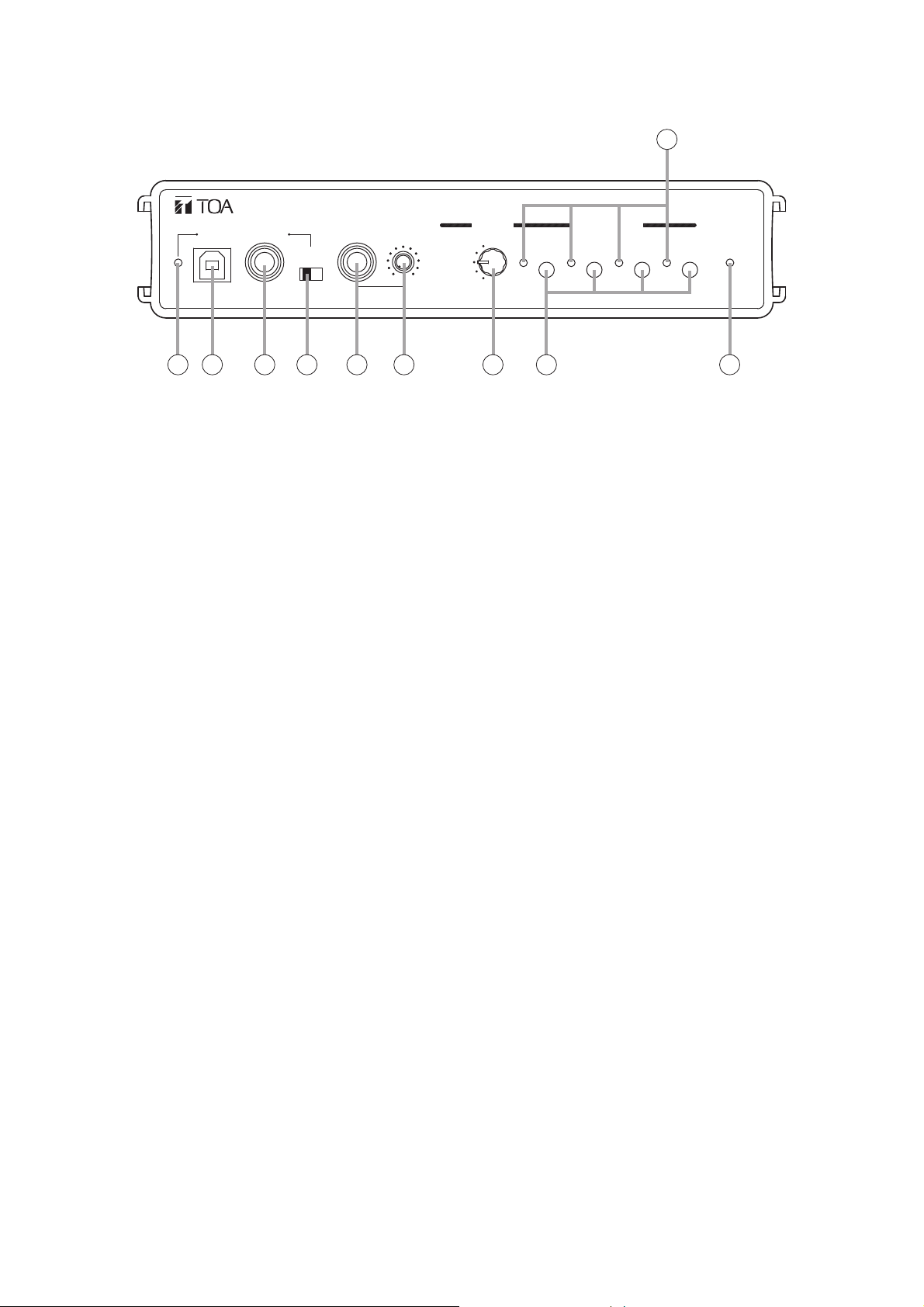
6. NOMENCLATURE AND FUNCTIONS
[Front]
1. Power Indicator [POWER]
Lights when the unit is powered up.
2. USB Communication Indicator
Continuously lights or flashes during USB
communications.
3. USB Terminal
Connects to a PC or a USB hub using the
supplied USB cable.
4. Input Terminal [INPUT/REC IN]
Connects to a microphone, CD player or other
sound source.
MIC signal level: –60 dB, 2.2 kΩ, phone jack,
unbalanced
LINE signal level: –20 dB, 10 kΩ, phone jack,
unbalanced
5. Input Level Selector Switch [LEVEL]
Set this switch to the MIC position (right side)
when connecting a microphone, and to the LINE
position (left side) when connecting other sound
source equipment.
Factory-preset to the LINE position.
Note: Set this switch to the LINE position when
not using a microphone.
6. Headphone Terminal [HEADPHONES]
Connects to a headphone.
0 dB, 100 Ω, phone jack, unbalanced
Note: No signal is provided from the Speaker
Output terminal (20) if the headphone is
connected.
7. Headphone/Speaker Volume Control
[PHONES/SPEAKER]
Adjusts the volume for the Headphone terminal
(6) or Speaker Output terminal (20).
8. Mode Selector Switch [MODE]
Selects the operation mode of the EV-20R.
• DEL: Deletes a message. (Refer to p. 8.)
• REC: Records a message.
(Refer to p. 7.)
• MONITOR: Verifies a message. (Refer to p. 8.)
• PLAY: Plays back and broadcasts a
message. (Refer to p. 8.)
• LOCK: Disables the Start/Stop key.
(Refer to p. 8.)
9. Start/Stop Key [START/STOP]
Starts and stops the selected message operating
in the mode set with the Mode Selector switch
(8).
10. Start/Stop Indicator
Continuously lights or flashes according to the
operating state.
HEAD-
USB
INPUT /
REC IN
LINE
LEVEL
MIC
PHONES
PHONES/
SPEAKER
010
REC
MONITOR
PLAY
DEL
LOCK
1234
10
START/STOPMODE
POWER
SOUND REPEATER EV-20R
12 3 4 5 6 7 8 9
Page 6
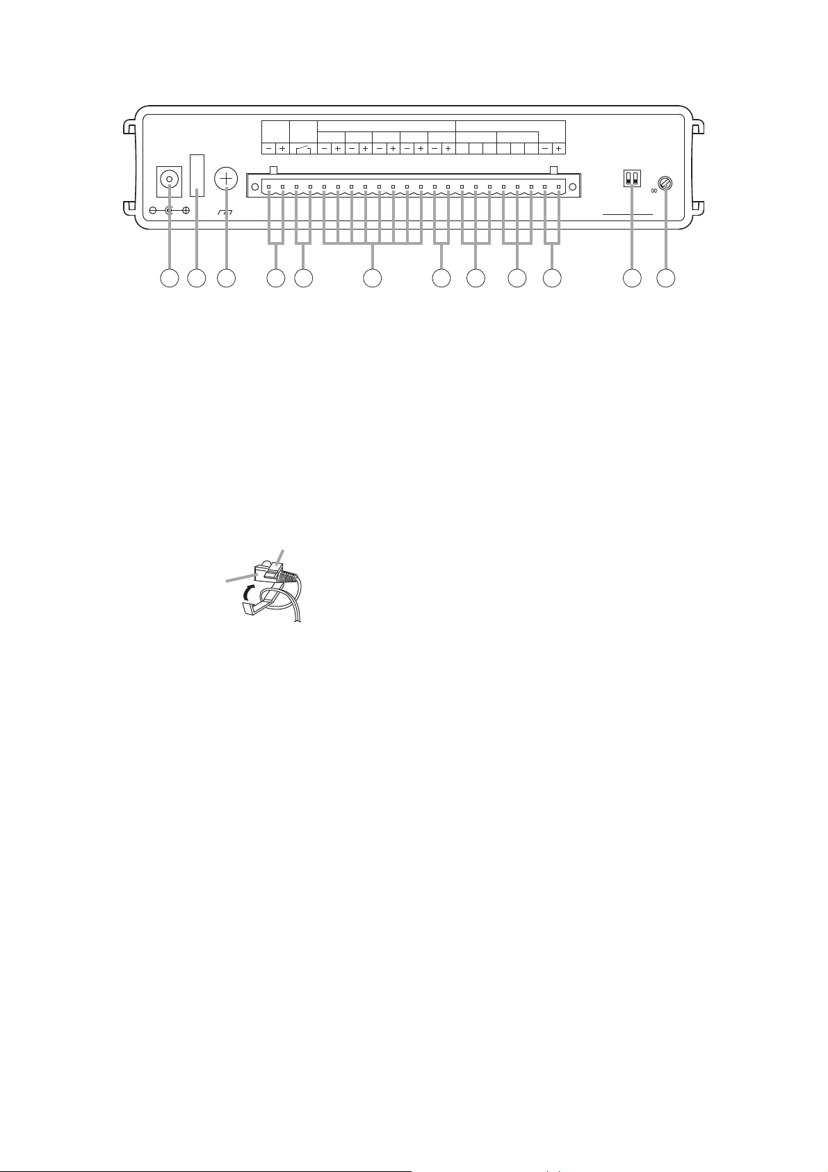
6
[Rear]
11. AC Adapter Input Terminal [DC IN]
Connects to the optional AD-246 AC adapter or
its equivalent.
Tip: When this terminal and the DC Power Input
terminal (14) are simultaneously used, the
terminal receiving the higher voltage takes
precedence.
12. Cord Clamp
Wrap the AC adapter cord around this clamp to
prevent the plug from pulling out.
13.Ground Terminal [SIGNAL GND]
Connect this terminal to the ground terminals of
the amplifier or other connected equipment.
14. DC Power Input Terminal [DC IN]
Connects to the 24 V DC power supply.
15. Busy Output Terminal [BUSY]
Following message activation, this terminal
remains at 'make' until playback is completed.
When repeat broadcast mode is selected by the
Playback Interval Setting switch (22), the busy
output during the set time intervals (except for "0
s" and "
∞" settings) can be set to "Make" (ON) or
"Break" (OFF) with the Delay Time Setting switch
(21). (Refer to p. 13.)
Contact capacity: 30 V DC, 0.5 A
16. Start Input Terminal [PLAY]
Triggers message playback when closed.
Contact: No-voltage 'make' contact, triggered by
pulse of over 200 ms in length.
17. Stop Input Terminal [STOP]
Stops playback when closed.
Contact: No-voltage 'make' contact, triggered by
pulse of over 200 ms in length.
18. Line Input Terminal [LINE IN]
Connects to external music playback equipment
for broadcast. When the EV-20R's message
broadcast is started during external equipment
broadcast, the message broadcast takes
precedence.
0 dB, 10 kΩ, unbalanced. (Refer to p. 13.)
19. Line Output Terminal [LINE OUT]
Provides output of playback messages or signals
input to the Line Input terminal (18).
0 dB, 600 Ω, unbalanced. (Refer to p. 13.)
Line Input terminal signals are not output during
message playback.
20. Speaker Output Terminal [SPKR]
Connect only low-impedance speakers to this
terminal.
21. Delay Time Setting Switch [DELAY]
Sets the delay time between message activation
and actual playback start. Also sets the busy
output during the time intervals (except for "0 s"
and "
∞" settings) to "Make" (ON) or "Break"
(OFF) when repeat broadcast mode is selected
by the Playback Interval Setting switch (22).
Setting the busy output to OFF makes the delay
time 0 seconds. (Refer to p. 13.)
The delay time is factory-preset to 0 seconds,
and the busy output during intervals between
repeated broadcasts to "Make" (ON).
(Refer to p. 13.).
22. Playback Interval Setting Switch
[INTERVAL TIMER]
Sets playback time intervals between repeated
broadcasts of the same message.
(Refer to p. 14.)
This switch is factory-preset to "∞" (Repeat
broadcasts disabled).
DC IN
BUSY
OUT24V STOP4321
DC IN
24V 400mA
N29
SIGNAL
GND
11 12 13 14 15 16 17 18 19 20 21 22
Cord clamp
PLAY 1 – 4 / STOP
TOA CorporationSOUND REPEATER EV-20R
Class 2 Wiring / 8 – 16 Ω
LINE IN LINE OUT
HCEECH
ENGINEERED IN JAPAN ASSEMBLED IN TAIWAN
SPKR
Tested to comply
with FCC standards
FOR HOME OR OFFICE USE
DELAY
4s2sON
INTERVAL
TIMER
10s
30s
5s
0s 5m
10m
1h 30m
1m
AC adapter plug
Page 7

7
7. OPERATION
7.1. Recording (REC)
Messages are recorded on the internal flash memory. Up to 4 messages can be recorded, totaling
approximately 6 minutes. Because the recording circuitry features automatic gain control (AGC) function, the
recording level does not need to be adjusted. When the Mode Selector switch is set to the REC position, the
input terminal signal is directed to only the Headphone terminal and Speaker Output terminal, and is not sent
to the Line Output terminal.
Note that the input signal to the Speaker Output terminal is cut when headphones are connected.
Step 1. Set the Mode Selector switch to the REC position.
Step 2. Set the Input Level Selector switch to the appropriate position for the type of
equipment connected to the Input terminal.
Set to MIC (right side) when a microphone is connected, and to LINE (left side)
when other equipment is connected.
Step 3. Connect the microphone, CD player or other equipment to the Input terminal.
Step 4. Press the Start/Stop key for the message number to be recorded, holding it down until the Start/Stop
indicator flashes. Recording begins when the indicator mode changes from flashing to steady ON.
(The indicator begins to flash 1 second after the key is pressed. It changes to steady ON 2 seconds
after flashing begins.)
Step 5. To stop the recording, press the corresponding Start/Stop key again.
Tips
• The Start/Stop indicator begins flashing when only 5 seconds of recording time remain, and continues until
recording is complete.
• Recording over a previously recorded message number automatically deletes the previous recording,
without requiring deletion by changing the Mode Selector switch position.
• Recording cannot be performed from the rear-mounted Line Input terminal.
• Sample chime tones contained in the supplied CD-ROM can be transferred to the EV-20R for use. It is also
possible to back up the messages using the data transfer software program contained in the supplied CDROM. For details, please read the "EV20 Software Instruction Manual.pdf" file located on the CD-ROM.
[Front]
Input Level Selector Switch
[Rear]
Busy Output Terminal
Input Terminal Headphone Terminal
INPUT /
USB
REC IN
LEVEL
MIC
LINE
HEAD-
PHONES
PHONES/
SPEAKER
010
MONITOR
PLAY
DEL
REC
LOCK
Mode Selector Switch Start/Stop Key
DC IN
24V 400mA
SIGNAL
GND
DC IN
BUSY
OUT24V STOP4321
PLAY 1 – 4 / STOP
Start/Stop Indicator
START/STOPMODE
1234
Class 2 Wiring / 8 – 16 Ω
LINE IN LINE OUT
SPKR
HCEECH
Speaker Output Terminal
Line Output Terminal
DELAY
4s2sON
POWER
INTERVAL
5s
0s 5m
TIMER
10s
1h 30m
30s
1m
10m
MONITOR
MODE
DEL
REC
PLAY
LOCK
Page 8

8
7.2. Confirming the Message (MONITOR)
The contents of recorded messages can be monitored and confirmed.
Messages being monitored can only be heard through the Headphone terminal and the Speaker Output
terminal, and are not directed through the Line Output terminal.
However, message output from the Speaker Output terminal is disabled if a headphone is connected.
Step 1. Set the Mode Selector switch to the MONITOR position.
The Start/Stop indicators for the recorded message numbers flash.
Step 2. Press the Start/Stop key of the message number to be monitored.
The Start/Stop indicator continuously lights, and monitor playback begins.
The Busy Output terminal is not closed during monitor playback.
Note: Rotating the Mode Selector switch during monitor playback causes
the message to stop.
Step 3. To stop monitor playback, press the corresponding Start/Stop key again.
7.3. Playback (PLAY)
Recorded messages can be played back.
The message played back is directed through both the Line Output and Speaker Output terminals. However, it
is not directed to the Speaker Output terminal if a headphone is connected.
In addition, the Busy Output terminal remains at make during playback.
Step 1. Set the Mode Selector switch to the PLAY position.
Step 2. Press the Start/Stop key of the message number to be played back.
The Start/Stop indicator lights and playback begins.
Operation automatically stops and the Start/Stop indicator extinguishes after
playback is completed.
Note: The message stops if the Mode Selector switch is rotated during playback.
Step 3. To interrupt the message partway through playback, press the corresponding Start/Stop key again.
7.4. Deletion (DEL)
To delete a message.
Step 1. Set the Mode Selector switch to the DEL position.
The Start/Stop indicators for the recorded message numbers flash.
Step 2. Hold down the Start/Stop key of the message number to be deleted
for 1 second or more.
Only the corresponding Start/Stop indicator stays flashing, while others extinguish.
The Start/Stop indicator extinguishes 3 seconds after the Start/Stop key has been pressed, indicating
deletion completion.
[To simultaneously delete all messages]
Hold down Start/Stop keys 1 and 4 for 3 seconds or more. All of the Start/Stop keys light, and deletion
begins. In approximately 40 seconds, the indicators will extinguish, indicating all messages have been
deleted.
7.5. Disabling the Start/Stop Key (LOCK)
Setting the Mode Selector switch to the LOCK position disables the Start/Stop key.
This setting helps prevent malfunctions, especially when operating the unit from only
the rear-mounted Start Input terminal.
MONITOR
MODE
DEL
REC
PLAY
LOCK
MONITOR
MODE
DEL
REC
PLAY
LOCK
MONITOR
MONITOR
MODE
DEL
REC
PLAY
LOCK
MODE
DEL
REC
PLAY
LOCK
Page 9

9
7.6. Using the Input and Line Input Terminals to Broadcast
Voice or audio from the microphone or CD player connected to the Input terminal (INPUT/REC IN) or the Line
Input terminal (LINE IN) can also be broadcast, except during the monitor playback of messages 1 – 4
(MONITOR mode) and during playback (PLAY mode). When repeat broadcast mode is selected by the
Playback Interval Setting switch, it can be set whether broadcasts from these inputs during the time intervals
(except for "0 s" and "∞" settings) are enabled or disabled. (Refer to p. 13.)
Tip
Whether signals from the Input and Line Input terminals are output or not is determined by the setting of the
Mode Selector switch and message operating state.
7.6.1. Input terminal [INPUT/REC IN]
7.6.2. Line input terminal [LINE IN]
Note
Signals are not directed through the Speaker Output terminal if the headphone is connected.
Mode Status
Line Output Terminal Speaker Output Terminal
[LINE OUT] [SPKR]
DEL Standby
Deletion in progress
REC Standby
Recording in progress
MONITOR Standby
Monitoring in progress
PLAY or LOCK Standby
Playback in progress
: Broadcast possible from the Input terminal.
: Broadcast not possible from the Input terminal.
Mode Status
Line Output Terminal Speaker Output Terminal
[LINE OUT] [SPKR]
DEL Standby
Deletion in progress
REC Standby
Recording in progress
MONITOR Standby
Monitoring in progress
PLAY or LOCK Standby
Playback in progress
: Broadcast possible from the LINE Input terminal.
: Broadcast not possible from the LINE Input terminal.
Page 10

10
8. INSTALLATION
8.1. Mounting a Single Unit in an Equipment Rack
Use the optional MB-WT3 Mounting Bracket to mount a single EV-20R unit.
8.2. Mounting Two Units in an Equipment Rack
Use the optional MB-WT4 Mounting Bracket to mount 2 EV-20R units.
8.3. Installing the Unit on a Desk
Attach the 4 supplied rubber feet to the bottom surface
of the unit when installing the unit on the desk.
Bracket B *
U
S
B
I
N
P
U
T
R
/
E
C
I
N
LE
V
L
I
E
N
L
E
M
IC
Fiber washer *
1
*1 Parts making up the MB-WT3 Bracket
EV-20R
H
E
A
D
P
-
H
O
N
E
P
H
O
N
S
E
P
S
E
/
A
K
E
R
M
O
0
D
D
E
E
L
R
E
L
C
1
I
S
0
T
E
N
P
L
A
Y
L
O
P
C
1
L
K
A
Y
/
S
T
O
P
2
3
4
P
O
W
E
R
S
O
U
N
D
RE
P
EA
T
ER
1
E
V
2
0
R
(for M5)
Rack mounting screw *
1
5 x 12
Bracket A *
1
Rack mounting screw *2
5 x 12
U
S
B
I
N
P
U
T
R
/
E
C
I
N
H
E
LE
A
D
P
V
L
-
H
I
E
N
O
L
E
N
E
P
M
H
O
IC
N
S
E
P
S
E
/
A
K
E
R
M
0
D
E
L
R
E
L
C
1
I
S
0
T
E
N
P
L
A
Y
L
O
C
K
Fiber washer *2
(for M5)
Connector *
O
D
E
P
1
L
A
Y
/
S
T
O
2
EV-20R
P
3
4
P
O
W
E
R
S
O
U
N
D
RE
P
EA
T
ER
E
V
2
0
R
2
U
S
B
I
N
P
U
T
R
/
E
C
I
N
H
E
LE
A
D
P
V
L
-
H
I
E
N
O
L
E
N
E
P
M
H
O
I
C
N
S
E
P
S
E
/
A
K
E
R
M
O
0
D
D
E
E
L
R
E
L
C
I
1
S
0
T
E
N
P
L
A
Y
L
O
P
C
1
L
K
A
Y
/
S
T
O
P
2
*2 Parts making up the MB-WT4 Bracket
EV-20R
3
4
P
O
W
E
R
S
O
U
N
D
RE
P
EA
T
ER
E
V
-
2
0
R
Bracket *
Rubber feet
(supplied with unit)
2
USB
LIN
E
REC IN
M
LEVEL
IC
IN
PUT/
0
10
PH
ON
LO
HEA
E
CK
PLAY
D-
SPEAKE
LISTEN
PHON
R
REC
ES/
DEL
M
ODE
1
SOUND
REPEA
2
TER EV
-20R
PLA
3
Y/ST
OP
4
POWER
Page 11

11
9. CONNECTIONS
9.1. Connection Example
*1Following activation, maintains make status until the message stops. When repeat broadcast mode is
selected by the Playback Interval Setting switch, the busy output during the time intervals (except for "0 s"
and "∞" settings) can be set to "Make" (ON) or "Break" (OFF). (Refer to p. 13.)
Use these outputs for amplifier power supply control.
*
2
Messages are played back when their corresponding terminal numbers are closed.
*
3
Message playback stops when these terminals are closed.
*
4
Used for BGM broadcasts, etc. Whenever a stored message is activated, the message playback broadcast
takes precedence.
[EV-20R Front]
INPUT/
REC IN
USB
USB cable
PC
(supplied with unit)
Remote control input of power amplifier, etc.
To AC mains, 50/60 Hz
(When operating unit on AC power supply)
[EV-20R Rear]
HEAD-
PHONES
LEVEL
MIC
LINE
Microphone
Remote control input
BUSY output
PHONES/
SPEAKER
MONITOR
010
or
CD player, etc.
1
*
REC
PLAY
DEL
LOCK
START/STOPMODE
1234
POWER
Headphone*
No signal is output from the
*
Speaker Output terminal if
the headphone is connected.
External audio source equipment
input*
4
LINE
Speaker
PLAY 1 – 4 / STOP
Class 2 Wiring / 8 – 16 Ω
LINE IN LINE OUT
HCEECH
SPKR
DELAY
4s2sON
INTERVAL
TIMER
10s
30s
5s
0s 5m
1h 30m
1m
10m
DC IN
24V 400mA
SIGNAL
GND
DC IN
BUSY
OUT24V STOP4321
AD-246 AC adapter
(optional)
PLAY
input*
2
STOP
input*3LINE
output
Power amplifier
24 V DC
power supply
(When operating unit on DC power supply)
Stop control output
Start control output
Timer or switching device
Page 12

12
9.2. Connections to the Rear-Mounted Connectors
Notes
• Use the appropriate type of screwdriver for the connector wiring screws.
• When using stranded or shielded cable, do not solder the stripped and exposed ends.
When the cable is clamped, the solder becomes crushed, increasing contact resistance and possibly
resulting in an extreme rise in cable joint temperature.
Conductor cross-sectional area 0.5 – 1.5 mm
2
AWG AWG24 – 16
Cable Type (Stranded Cable) Maximum Distance
0.5 – 1.5 mm
2
20 m
Solid and stranded cables
Shielded cable
6 mm
6 mm
15 mm
9.2.1. Matching cable size
9.2.2. Stripped cable end
9.2.3. Cable connections
9.2.4. Maximum speaker output cable distance
Step 1. Loosen the terminal screw to insert the cable
into the connector, then retighten the screw.
Note
Tug lightly on the cable to be sure that it does
not pull free. If the cable pulls free, loosen the
terminal screw again and reconnect from the
beginning.
Step 2. Insert the connector into the rear-mounted
socket.
Step 3. Tighten the fixing screw.
Note
Take care not to reverse Steps 1 and 2.
When tightening the terminal screw, force is applied to
the connector pins on the internal circuit board,
possibly resulting in poor contact.
Refer to the following table for the distance of the cable to be connected to the Speaker Output terminal.
Tighten
Terminal screw
Connector
(Accessory)
1
Flat-blade screwdriver
Loosen
To unit's rear panelmounted socket
2
Fixing screw
3
Page 13

13
9.2.5. Line input and output terminal connections
Both the Line Input and Output terminals can be converted into balanced types by using optional IT-450
Balanced Transformers. For details, consult with your TOA representative.
10. BROADCAST DELAY TIME AND BUSY OUTPUT ON/OFF SETTINGS
The delay time between message activation and the actual start of playback can be set to 0, 2, or 4 seconds
with the unit's rear-mounted Delay Time Setting switch. When repeat broadcast mode is selected by the
Playback Interval Setting switch, the busy output during the time intervals (except for "0 s" and "∞" settings)
can be set to "Make" (ON) or "Break" (OFF).
(Factory-preset to "0" seconds , and the busy output during intervals between repeated broadcasts to "ON".)
Should the beginning of playback contents be lost due to operational delays experienced by connected
external equipment, set the delay time to 2 or 4 seconds.
Note: If the delay time is set to 2 or 4 seconds, the Busy Output terminal is closed during the delay as well.
[Line Input Terminal]
Unbalanced type (as shipped from factory) Balanced type (with IT-450)
LINE IN
CE
H
LINE IN
CE H
To external
playback equipment
To external
playback equipment
[Line Output Terminal]
Unbalanced type (as shipped from factory) Balanced type (with IT-450)
LINE OUT
CE
H
To power amplifier To power amplifier
LINE OUT
CEH
Delay time
2 seconds 4 seconds
Set Delay Time
Delay Time
Setting Switch
Operation during Time Intervals *
Busy Output Broadcasts using the Input
and Line Input Terminals *
4s2sON
0 seconds
(Factory-preset)
2 seconds
4 seconds
0 seconds
1
Valid only when the time intervals (except for "0 s" and "∞" settings) between repeated broadcasts are
*
4s2sON
4s2sON
4s2sON
4s2sON
ON (Make)
ON
ON
OFF (Break)
Disabled
Disabled
Disabled
Enabled
set by the Playback Interval Setting switch.
2
Broadcasts using the front-mounted Input terminal (INPUT/REC IN) and rear-mounted Line Input
*
terminal (LINE IN).
1
2
Page 14

14
Playback Interval Setting Switch
∞
(Factory-preset position)
0 s
5 s
10 s
30 s
1 m
5 m
10 m
30 m
1 h
11. PLAYBACK INTERVAL SETTINGS
The time interval between repeated message announcements can be set with the Playback Interval Setting
switch on the rear panel.
The repeat interval represents the time between the end of the previous message and the start of the next
message. Set delay times are not added to the repeat interval.
Set the indentation on the switch axis (marked in black in the figure at right) to the
desired timer interval.
Note: The switch is factory-preset to the "
∞" position (announcement repetition
disabled).
Setting Contents
No repeat announcements are broadcast.
However, even when "∞" is selected, if the Start Input terminal is
continuously closed, the same announcement is continuously
broadcast with no interval. Also, opening the input terminal while a
broadcast is in progress causes the message to stop immediately
after the current playback ends.
Continuous broadcasts with no pause.
Broadcasts are repeated after each 5-second pause.
Broadcasts are repeated after each 10-second pause.
Broadcasts are repeated after each 30-second pause.
Broadcasts are repeated after each 1-minute pause.
Broadcasts are repeated after each 5-minute pause.
Broadcasts are repeated after each 10-minute pause.
Broadcasts are repeated after each 30-minute pause.
Broadcasts are repeated after each 1-hour pause.
Notes
• The Start/Stop indicator flashes until the next message broadcast begins following the end of the previous
message broadcast.
• To stop repeat broadcast while in progress, either press the Start/Stop key of the message number being
broadcast or close the Stop Input terminal.
INTERVAL
TIMER
10s
30s
5s
1m
0s 5m
10m
1h 30m
Page 15

15
12. PLAYBACK OPERATIONS AND CONTROL I/O TIMING
12.1. Stopping Broadcasts during Manual Playback or Switching Message Playback
[Operation]
• Pressing the Start/Stop key closes the Busy Output terminal until playback is completed. If the same key is
pressed during playback, the playback stops and the Busy Output terminal opens.
• If the Start/Stop key of another message is pressed during playback, playback stops, allowing the most
recently activated message to be played back with no delay time.
Note: Current playback can also be made to stop by closing the Stop Input terminal.
Start/Stop Key 1
Start/Stop Key 3
Output
Busy output
Activation Stop
Delay
time
Message 1 playback
Stop
Activation
Switching to Message 1
Delay
time
Message 3 playback Message 1 playback
Activation
Page 16

16
12.2. Making Repeat Broadcasts
[Operation]
• Pressing the Start/Stop key or closing the Start Input terminal closes the Busy Output terminal and plays
back the message after the set delay time elapses.
• When playback ends, the same playback starts again after the time interval between repeat broadcasts
elapses. (Refer to p. 14.)
Since then, this operation repeats.
• To interrupt the repeat broadcast, press the in-use message number or close the corresponding Stop Input
terminals.
• The busy output during repeat intervals can be set to ON (Make) or OFF (Break) with the Delay Time Setting
switch. (Refer to p. 13.)
Depending on the busy output ON/OFF settings, operation differs as follows:
Setting the busy output to ON: No broadcast can be made during the repeat intervals.
Setting the busy output to OFF: Permits broadcasts using the front-mounted Input terminal (INPUT/REC IN)
and rear-mounted Line Input terminal (LINE IN) during the repeat intervals.
Activation Stop
Start/Stop key 1
(Start and Stop Inputs)
When the busy output
during repeat intervals
is set to "Make" (ON)
Output
Busy output
When the busy output
during repeat intervals
is set to "Break" (OFF)
Output
Busy output
Delay
time
Message 1 playback Message 1 playback
Message 1 playback
Repeat interval
Stop
Silence
Broadcasts using the Input and
Line Input terminals can be made.
Message 1 playback
Page 17

17
12.3. Playing Back Messages through External Activation
12.3.1. Message activation
[Operation]
• Closing the Start Input terminal closes the Busy Output terminal and plays back the message after the set
delay time elapses. Even if the Start Input terminal opens during playback, the message continues to be
played back until it is completed.
• Continuously closing the Start Input terminal causes the same message to be repeatedly played back. Delay
time settings are disabled during the repeat playback.
• If the front-mounted Stop key is pressed or the Stop Input terminal is closed during playback, the playback
stops, opening the Busy Output terminal as well.
• Closing the Stop input terminal while the Start input terminal is continuously closed stops the playback.
12.3.2. Simultaneous multiple message activation or activation of other message during playback
[Operation]
• When two or more Start Input terminals are simultaneously closed, the message with the lower message
number is played back, making other messages invalid.
• Closing another Start Input terminal during playback causes the current playback to stop, allowing the
message activated later to be played back without the delay time.
• Even if the same Start Input terminal is closed during playback, the playback is not repeated.
• Closing another Start input terminal while a Start input terminal is continuously closed allows the message
activated later to be played back.
200 ms or longer
Activation input 1
Busy output
If continuously closed
Output
Stop input
Delay
time
Message 1 playback Message 1 playback
Stop
200 ms or longer
200 ms or longer
Start input 2
Start input 3
Start input 4
Busy output
Output
Message 2
playback stops
Delay
time
Message 2 playback Message 3 playback
Delay
time
Message 2
playback stops
Message 2 playback Message 4 playback
Page 18

18
13.2. CD-ROM File Configuration
The unit's supplied CD-ROM is configured as follows:
* Acrobat Reader is required to view this file. If Acrobat Reader is not installed in the PC to be
used, download it from the Adobe web site.
Note: Both Adobe and Acrobat are trademarks of Adobe Systems Incorporated.
CD-ROM
Driver
ReadmeENG.txt
English
Sample data
Sample data table.pdf *
EV20ENG.msi
EV20 Software
Instruction Manual.pdf *
Contains the USB driver necessary for USB connection of the
EV-20R to a PC.
Contains the supplied software's system requirements and
update log data. Please read this before using the software.
Contains the following folders and files in English.
Contains sample chime tone data.
Shows the contents of sample data.
Use this when installing the data transfer software program.
Instructions for the data transfer software program.
Read this file after installing the software program.
ReadmeJPN.txt
Japanese
Japanese version of ReadmeENG.txt.
PCs require Japanese OS for correct operation.
Contains a software program, data, instruction manual, etc. of
Japanese version.
PCs require Japanese OS for correct operation.
13. USING THE SUPPLIED SOFTWARE
The EV-20R is equipped with a USB interface jack.
The following operations can be carried out by connecting a PC using the supplied USB cable:
• Uploading the chime tone contained in the supplied CD-ROM.
• Downloading recorded data to the PC. (Recorded data backup)
• Uploading data backed up in the PC.
For instructions regarding installation and use of the supplied software, read the "EV20 Software Instruction
Manual.pdf" file located on the CD-ROM.
13.1. System Requirements
The following PC specifications are highly recommended for correct operation of the unit's software.
Notes
• Pentium is the trademark of Intel Corporation in the United States and other countries.
• Windows and Windows Vista are the registered trademarks of Microsoft Corporation in the United States and
other countries.
Personal Computer Windows PC (equipped with the USB terminal)
Main Specifications CPU: Pentium compatible CPU of 300 MHz or more
Memory: Over 128 MB
Free disk space: Over 10 MB (space for message storage excluded)
Optical drive: CD-ROM drive
OS Windows XP (32-bit version)/Vista (32-bit version)/7 (32-bit version)
Page 19

19
13.3. Notes on Use of Software
• When the EV-20R is in the following operating states, do not switch off its power nor insert or remove the
USB cable. PC operation may stop.
• While the driver software program is being installed.
• While the OS is being activated or terminated.
• During the course of being suspended or resumed.
• While data is being transferred between the unit and the PC.
• While the sound source is being written or read.
• While the USB communication indicator is lit.
Because PC operations could also freeze, avoid performing the following:
• Frequent ON and OFF power switching
• Frequent USB cable insertion and detachment
• CD-ROM's sample audio data can only be used with the EV-20R, PM-20EV, EV-20A, EV-20S, and S-20S.
Never use the data with other products. When wishing to use them with other products than specified,
contact your TOA dealer.
Symptom
Cannot record.
Recorded sounds
distorted.
14. TROUBLESHOOTING
Remedy
Limit total recording time of 4 messages
to under 6 minutes.
Set the Input Level Selector switch to
MIC position (right side) when the
microphone is connected, and to LINE
position (left side) when connecting
other equipment.
Cause
Previously recorded messages
reached a total of 6 minutes.
The Input Level Selector switch is not
correctly set during recording.
Page 20

• Optional products
Rack mounting bracket: MB-WT3 (for rack mounting one EV-20R unit)
MB-WT4 (for rack mounting two EV-20R units)
AC adapter: AD-246
Note: Consult your TOA dealer when using an equivalent adapter.
133-12-831-2D
URL: http://www.toa.jp/
15. SPECIFICATIONS
Power Source Supplied from an external 24 V DC /400 mA power supply or
from an optional AD-246 AC adapter or its equivalent
Power Consumption 10 W (rated output)
Wave Format 44.1 kHz sampling frequency, 16-bit PCM (monaural)
Frequency Response 20 – 20,000 Hz ±3 dB (1 kHz)
50 – 14,000 Hz ±3 dB (IT-450 mounted, 1 kHz)
Distortion Under 1% (1 kHz, rated output)
Recording System USB data transfer or analog recording
Control Input
Activations 1 – 4, stop: No-voltage make contact input,
pulse make length: 200 ms, open voltage: 30 V DC,
short-circuit current: 10 mA, terminal block type connector
Control Output Busy: Contact capacity 30 V DC/ 0.5 A, terminal block type connector
Input
Input/ Recording input: Mic / Line changeable,
–60 dB*12.2 kΩ (MIC), –20 dB*110 kΩ (LINE),
unbalanced, phone jack
Line input: 0 dB*1, 10 kΩ, unbalanced, terminal block type connector
Output Line output: 0 dB*1, 600 Ω, unbalanced, terminal block type connector
Headphone output: 0 dB*1, 100 Ω, unbalanced, phone jack
Speaker output: 3 W, 8 Ω, terminal block type connector
LED Indicator POWER, USB, START /STOP 1 – 4
Maximum No. of Messages
4
Pre-recorded audio data: Message 1 (Westminster chime
*2)
Message 2 (Ascending 4-tone chime
*2)
Message 3 (Descending 4-tone chime
*2)
Message 4 (None)
Note: The above audio sources can be overwritten by using the supplied
software.
Maximum Recording Time
6 minutes
Message Delay Time 0, 2 s, or 4 s (selectable)
Playback Interval Time
∞
, 0, 5 s, 10 s, 30 s, 1 min, 5 min, 10 min, 30 min, or 1 h (selectable)
Finish Case: ABS resin, black
Dimensions 210 (w) x 44.2 (h) x 181 (d) mm (excluding projection)
Weight 730 g
Accessories CD-ROM … 1, USB cable (1 m) … 1, Unbalanced phone plug … 1
Removable terminal plug (22 P) … 1, Rubber foot … 4
*10 dB = 1 V
*2Also contained in the supplied CD-ROM as sample audio data.
Note: The design and specifications are subject to change without notice for improvement.
 Loading...