

Page 1
OPERATING INSTRUCTIONS
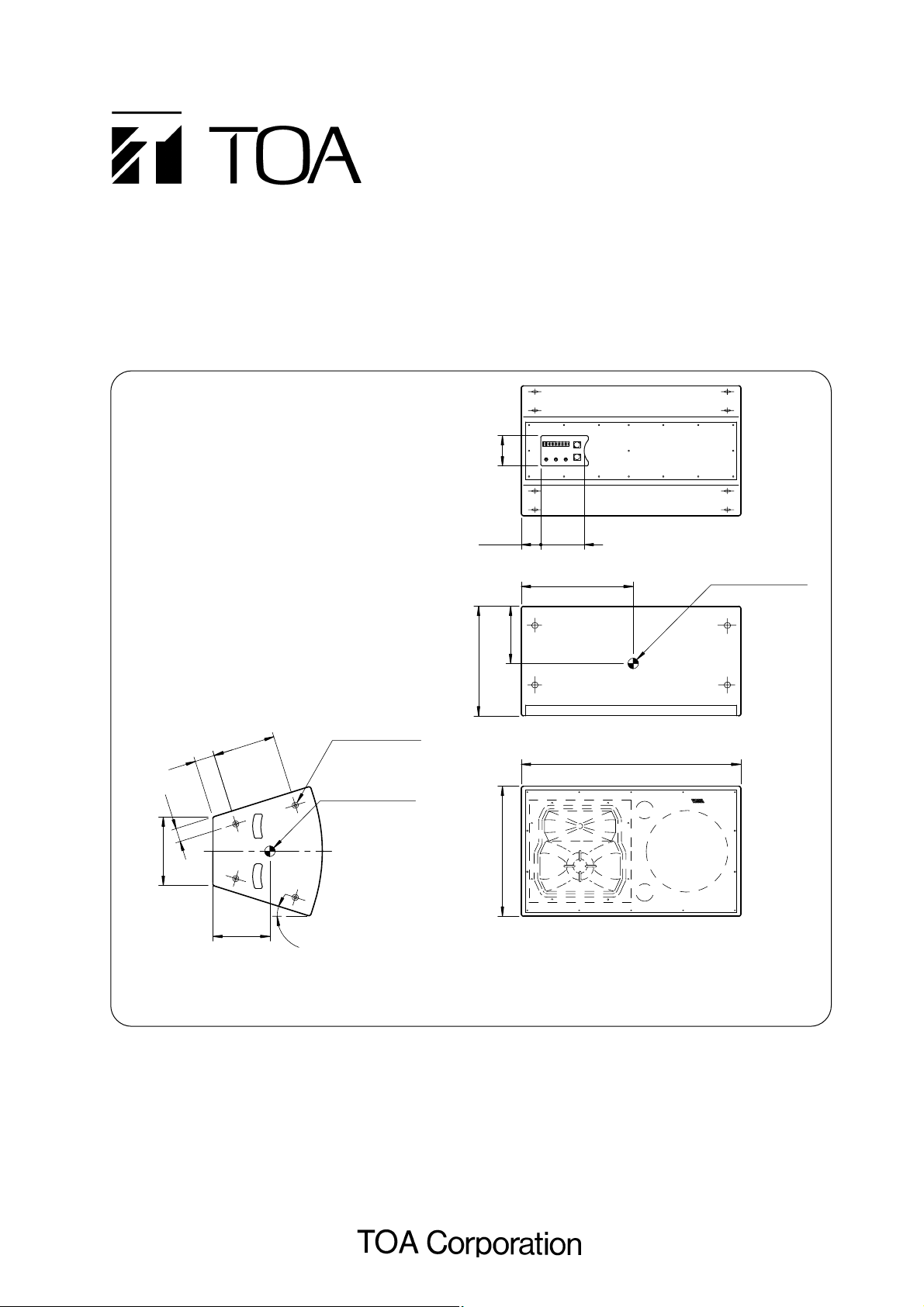
SPEAKER SYSTEM
ES-5071-95
ES-5071-65
130
245
470
558
294
83.5 186
480
[Rear]
[Top]
[Front]
[Side]
942
17.5°
245
268
85
58
Unit: mm
Gravity position
Gravity position
16-M12 nuts
Please follow the instructions in this manual to obtain the optimum results from this unit.
We also recommend that you keep this manual handy for future reference.
This figure is for the ES-5071-95. Note that the ES-5071-65 differs in horn size.
Page 2

TABLE OF CONTENTS
1. SAFETY PRECAUTIONS ................................................................................ 3
2. GENERAL DESCRIPTION ............................................................................. 4
3. FEATURES .......................................................................................................... 4
4. INSTALLATION .................................................................................................. 5
5. INPUT CONNECTORS .................................................................................... 6
6. WIRING DIAGRAM ........................................................................................... 6
7. CONNECTIONS
7.1. Single-Amplification System .......................................................................... 7
7.2. Dual-Amplification System ............................................................................. 7
7.3. Triple-Amplification System ........................................................................... 7
8. SELECTION OF MULTI-AMPLIFICATION DRIVE SYSTEM
8.1. Single-Amplification System .......................................................................... 8
8.2. Dual-Amplification System ............................................................................. 8
8.3. Triple-Amplification System ........................................................................... 8
9. MULTI-AMPLIFICATION PROCESSOR SETTINGS
9.1. Dual-Amplification System ............................................................................. 9
9.2. Triple-Amplification System ........................................................................... 9
10. CHANGING HORN DIRECTIVITY ANGLE ............................................. 10
11. SPEAKER UNIT REPLACEMENT ............................................................. 11
12. SPECIFICATIONS ........................................................................................... 12
Page 3
3
1. SAFETY PRECAUTIONS
• Be sure to read the instructions in this section carefully before use.
• Make sure to observe the instructions in this manual as the conventions of safety symbols and messages
regarded as very important precautions are included.
• We also recommend you keep this instruction manual handy for future reference.
Safety Symbol and Message Conventions
Safety symbols and messages described below are used in this manual to prevent bodily injury and property
damage which could result from mishandling. Before operating your product, read this manual first and
understand the safety symbols and messages so you are thoroughly aware of the potential safety hazards.
Indicates a potentially hazardous situation which, if mishandled, could
result in death or serious personal injury.
Indicates a potentially hazardous situation which, if mishandled, could
result in moderate or minor personal injury, and/or property damage.
WARNING
CAUTION
When Installing the Unit
• Install the unit only in a location that can
structurally support the weight of the unit and the
mounting bracket. Doing otherwise may result in
the speaker falling down and causing personal
injury and/or property damage.
• Refer all installation work to the dealer from whom
the speaker was purchased. Installation requires
extensive technical knowledge and experience.
The speaker may fall off if incorrectly installed,
resulting in possible personal injury.
When the Unit is in Use
• Should the following irregularity be found during
use, immediately stop operating the speaker and
contact your nearest TOA dealer. Make no further
attempt to operate the unit in this condition as this
may cause fire or electric shock.
· If you detect smoke or a strange smell coming
from the unit.
· If water or any metallic object gets into the unit
· If the unit falls, or the unit case breaks
· If it is malfunctioning (no tone sounds.)
• Have the speaker unit checked periodically by the
shop from where it was purchased. Failure to do so
may result in corrosion or damage to the speaker
or its mounting bracket that could cause the
speaker to fall, possibly causing personal injury.
When Installing the Unit
• When unpacking or moving a heavy speaker, be
sure to handle the unit with two or more persons.
Falling or dropping the speaker may cause
personal injury and/or property damage.
When the Unit is in Use
• Do not stand or sit on, nor hang down from the
speaker as this may cause it to fall down or drop,
resulting in personal injury and/or property
damage.
• Do not operate the speaker for an extended period
of time with the sound distorting. This is an
indication of a malfunction, which in turn can cause
heat to generate and result in a fire.
WARNING CAUTION
Page 4

4
2. GENERAL DESCRIPTION
TOA's ES-5071-95 and ES-5071-65 speaker systems are suitable for use as main speaker in halls or theater
applications.
3. FEATURES
• Both models are 3-way speaker systems employing the "voice-range-per-unit" configuration to cover the
frequency range of the human voice with a single speaker unit. The voice range is reproduced by a midrange horn speaker featuring a KEVLAR* fiber cone (speaker diaphragm using chemical fibers).
* KEVLAR is a registered trademark of Du Pont in the United States.
• The speaker's new horn pattern control corrects the inherent tendency of conventional constant directivity
horns to narrow oblique radiation patterns.
• The horn's directivity angle is set for 90° horizontal x 50° vertical (ES-5071-95) over short distances, and 60°
horizontal x 50° vertical (ES-5071-65) over long distances.
• The enclosure features trapezoidal "sides" when viewed in a horizontal installation. The angle of inclination
is optimal for reducing interference in the vertical plane when the short-distance speaker and the longdistance speaker are vertically joined.
• Both the mid-range and high-range horns can be rotated in 90° steps to permit both horizontal and vertical
speaker installations.
• The speakers can be easily adapted to single, dual, or triple amplification systems with the mode switches.
• The speakers' built-in crossover circuitry has been designed with an emphasis on phase matching at the
crossover frequency for smooth acoustic characteristics.
• Both M5 screw terminals and Neutrik NL4MP (parallel) connectors are used for input terminals. The Neutrik
connectors can be used in both single- and dual-amplification system applications.
• Each side surface features 4-M12 suspension holes, making available a total of 16 suspension holes.
Handles on two trapezoidal sides facilitate carrying and installation of the speaker.
• All speaker units can be easily accessed from the rear of the enclosure.
• The enclosure is finished in leather-tone paint that gives a high sense of quality.
Page 5

5
4. INSTALLATION
WARNING
Refer all installation work to the dealer from whom the speaker was
purchased. Installation requires extensive technical knowledge and
experience. The speaker may fall off if incorrectly installed, resulting in
possible personal injury.
When installing, mounting brackets of the type suited to the conditions of the installation place must be
prepared.
• Representative installation examples
Suspend the speaker at its sides. It is recommended that headless bolts be used for installation.
[Single speaker suspension]
[Jointed 2-speaker suspension]
[Vertical suspension]
• Do not use the following suspension methods.
Important: Avoid using only the top panel for suspension.
Page 6

6
5. INPUT CONNECTORS
• Input connectors are located on the rear panel as shown below:
• For connections of the NL4MP and screw terminals in each amplification system, refer to the table below:
• The connector (of the connection cable) that can be used for the Neutrik NL4MP is the Neutrik NL4FC.
6. WIRING DIAGRAM
For inner wiring, refer to the following diagram:
Neutrik NL4MP connector
Screw terminal
Neutrik NL4MP Screw terminal
1 + INPUT 1 + Full range + Low + Low+
1 – INPUT 1 – Full range – Low – Low –
2 + INPUT 2 + Mid & High + Mid +
2 – INPUT 2 – Mid & High – Mid –
INPUT 3 + High +
INPUT 3 – High –
Single amplification Dual amplification Triple amplification
(SINGLE-AMP) (BI-AMP) (TRI-AMP)
INPUT 1 INPUT 2 INPUT 3
Screw terminal
2
2
2
2
NL4MP
1
1
1
1
Switch circuitry
Network or individual units
Page 7

7
7. CONNECTIONS
7.1. Single-Amplification System
7.2. Dual-Amplification System
7.3. Triple-Amplification System
INPUT
ES-5071-95, ES-5071-65
Power amplifier
INPUT 1
DP-0204 (SR)
LOW
INPUT
MID & HIGH
DP-0204 (SR)
LOW
INPUT
MID
HIGH
Power amplifier
Power amplifier
ES-5071-95, ES-5071-65
INPUT 1
INPUT 2
ES-5071-95, ES-5071-65
INPUT 1
INPUT 2
INPUT 3
Page 8

8
8. SELECTION OF MULTI-AMPLIFICATION DRIVE SYSTEM
Use the three rear panel mode switches to select the desired drive mode. Loosen the switch panel mounting
screws to operate the mode switches. Set the switches as shown below depending on the drive system used,
then retighten the mounting screws to secure the switch panel. Note that the switches are set at the factory for
single-amplifier applications.
8.1. Single-Amplification System
8.2. Dual-Amplification System
8.3. Triple-Amplification System
Mode switch
Mode switch position
Mode switch
Mode switch
Mounting screw
Mode switch position
Mounting screw
Switch panel
Switch panel
Mode switch position
Mounting screw
Switch panel
Page 9

9
9. MULTI-AMPLIFICATION PROCESSOR SETTINGS
When using TOA's digital signal processor in conjunction with multiple amplifiers to drive the speaker, perform
the following settings for the processor.
9.1. Dual-Amplification System
9.2. Triple-Amplification System
Horizontal Installation Vertical Installation
Channel
Low 0 Normal LPF 210
MID & HIGH 1 Normal
Gain Polarity DelayFilter
(dB) (dB)(msec) (msec)TYPE Freq. Gain Q
0.707 0.104
LPF 210 0.707
PEQ 165
PEQ 320
PEQ 500
HPF 220 0.707
HPF 220 0.707
PEQ 540 2.016
PEQ 2100 3.0 4.318
PEQ 3000
PEQ 3700
PEQ 7400
-
2.5 4.318
-
4.0 4.318
-
4.0 4.318
-
14.0
-
5.0 6.919
-
2.0 4.318
-
2.0 4.318
Gain Polarity DelayFilter
TYPE Freq. Gain Q
0 Normal LPF 210
LPF 210 0.707
PEQ 165
PEQ 320
PEQ 500
0
1 Normal
HPF 220 0.707
HPF 220 0.707
PEQ 540 2.251
PEQ 1000
PEQ 2100 3.0 4.318
PEQ 3000
PEQ 4300
-
0.707 0.146
-
2.5 4.318
-
4.0 4.318
4.318
-
4.0
11.5
-
2.0 2.871
-
5.0 6.919
-
1.5 3.134
0
Horizontal Installation
Channel
Low 0 Normal LPF 210
MID 0 Normal
HIGH
Gain Polarity DelayFilter
(dB) (msec)TYPE Freq. Gain Q
LPF 210 0.707
PEQ 145
PEQ 500
HPF 220 0.707 0
HPF 220 0.707
LPF 2000 0.707
LPF 2000 0.707
PEQ 273
PEQ 550
PEQ 1520
-
4.5 Invert
HPF 2000 0.707 0.042
HPF 2000 0.707
PEQ 2600
PEQ 3080
PEQ 3810
PEQ 9500
PEQ 15000 4.0 2.871
0.707 0
-
2.5 1.958
-
4.0 4.318
-
2.0 2.215
-
12.5 2.215
-
3.0 4.318
-
2.0 4.318
-
4.5 4.608
-
9.5 2.871
-
1.5 4.318
Vertical Installation
Gain Polarity DelayFilter
(dB) (msec)TYPE Freq. Gain Q
0 Normal LPF 210
LPF 210 0.707
PEQ 129
PEQ 160
0 Normal
-
5 Invert
HPF 220 0.707 0
HPF 220 0.707
LPF 2000 0.707
LPF 2000 0.707
PEQ 550
HPF 2000 0.707 0.042
HPF 2000 0.707
PEQ 2700
PEQ 3800
PEQ 6750
PEQ 9500
PEQ 14400 4.5 1.624
-
0.707 0.146
-
1.5 4.318
-
1.5 4.318
11.5 2.215
-
5.0 3.836
-
8.0 3.450
-
2.0 4.318
-
1.5 4.318
Page 10

10
10. CHANGING HORN DIRECTIVITY ANGLE
Mid-range and high-range horns can be rotated in 90°steps. Use this function when switching from horizontal
to vertical installation or when lining up two speakers symmetrically. Follow the procedures below to rotate the
horns.
1. Remove all 14 screws (M5x10) holding the front
grille in place, and detach the grille.
2.Remove all 8 screws (M5x40) holding the horn
baffle in place, and detach the horns.
3. Remove all 8 screws (M5x40) holding the unit baffle,
and rotate the unit baffle to the desired angle. (The
unit baffle can be rotated without taking it out of the
enclosure.) It is possible to rotate the unit baffle in
90° steps.
4. Retighten the 8 unit baffle mounting screws.
5. Replace the horns, and retighten the 8 horn baffle
mounting screws.
6. Replace the front grille, and retighten the 14
mounting screws.
Page 11

11
Speaker unit
Rear view with the rear
cover removed
Speaker unit
M5x45 screw
M5x30 screw
M5x30 screw
New speaker unit
New speaker unit
Note
In the above figure, only a
portion of the speaker unit
mounting screws are exposed.
However, all mounting screws
can be accessed through the
opening with a screwdriver.
11. SPEAKER UNIT REPLACEMENT
Follow the procedures below to replace the speaker unit:
1. Remove all 17 screws (M5x40) holding the rear
cover in place, and detach the rear cover.
2. Detach the speaker cable from each speaker unit.
3. Remove all 4 screws holding each speaker unit in
place, and take out the speaker unit.
4. Place the new unit in the mounting position. The
positioning block and concave facilitate unit
positioning.
5. Retighten the 4 speaker unit mounting screws.
6. Connect the speaker cables to the speaker unit.
7. Replace the rear cover, and retighten the 17
mounting screws.
Page 12

12. SPECIFICATIONS
• ES-5071-95
133-01-417-2A
Enclosure Bass-reflex type
Permissive Input Continuous program, Full range: 600 W, Mid-/high-range: 360 W,
Low-range: 600 W, Mid-range: 450 W, High-range: 120 W
Rated Impedance Full range: 8Ω, Mid-/high-range: 8Ω, Low-range: 8Ω, Mid-range: 8Ω,
High-range: 8Ω
Output Sound Pressure Full range: 98 dB (1 W, 1 m), Mid-/high-range: 102 dB (1 W, 1 m),
Level Low-range: 98 dB (1 W, 1 m), Mid-range: 102 dB (1 W, 1 m),
High-range: 105 dB (1 W, 1 m)
Frequency Response 60 Hz - 20 kHz
Crossover Frequency 250 Hz, 2 kHz
Speaker Low: 38 cm-diameter cone
Mid: Constant directivity horn 90° horizontal x 50° vertical + 20 cm-diameter cone
High: Constant directivity horn 90° horizontal x 50° vertical + compression driver
Input Connector M5 screw terminal (distance between barriers: 12.2 mm) and
Neutrik NL4MP x 2 (usable connector: Neutrik NL4FC)
Finish Enclosure: Plywood, black, urethane paint
Grille: Rolled carbon steel plate, black, acrylic paint
Dimensions 942(w) x 558(h) x 470(d) mm
Weight 62 kg
Note : The design and specifications are subject to change without notice for improvement.
Enclosure Bass-reflex type
Permissive Input Continuous program, Full range: 600 W, Mid-/high-range: 360 W,
Low-range: 600 W, Mid-range: 450 W, High-range: 120 W
Rated Impedance Full range: 8Ω, Mid-/high-range: 8Ω, Low-range: 8Ω, Mid-range: 8Ω,
High-range: 8Ω
Output Sound Pressure Full range: 98 dB (1 W, 1 m), Mid-/high-range: 102 dB (1 W, 1 m),
Level Low-range: 98 dB (1 W, 1 m), Mid-range: 102 dB (1 W, 1 m),
High-range: 106 dB (1 W, 1 m)
Frequency Response 60 Hz - 20 kHz
Crossover Frequency 250 Hz, 2 kHz
Speaker Low: 38 cm-diameter cone
Mid: Constant directivity horn 60° horizontal x 50° vertical + 20 cm-diameter cone
High: Constant directivity horn 60° horizontal x 50° vertical + compression driver
Input Connector M5 screw terminal (distance between barriers: 12.2 mm) and
Neutrik NL4MP x 2 (usable connector: Neutrik NL4FC)
Finish Enclosure: Plywood, black, urethane paint
Grille: Rolled carbon steel plate, black, acrylic paint
Dimensions 942(w) x 558(h) x 470(d) mm
Weight 62 kg
• ES-5071-65
 Loading...