

Page 1
Operating Instruction Manual
TOA PROFESSIONAL GRAPHIC EQUALIZER
Model E 131
TO A ELECTRIC CO., LTD.
KOBE, JAPAN
Page 2

Contents
Precautions
General Description
Features
Specifications
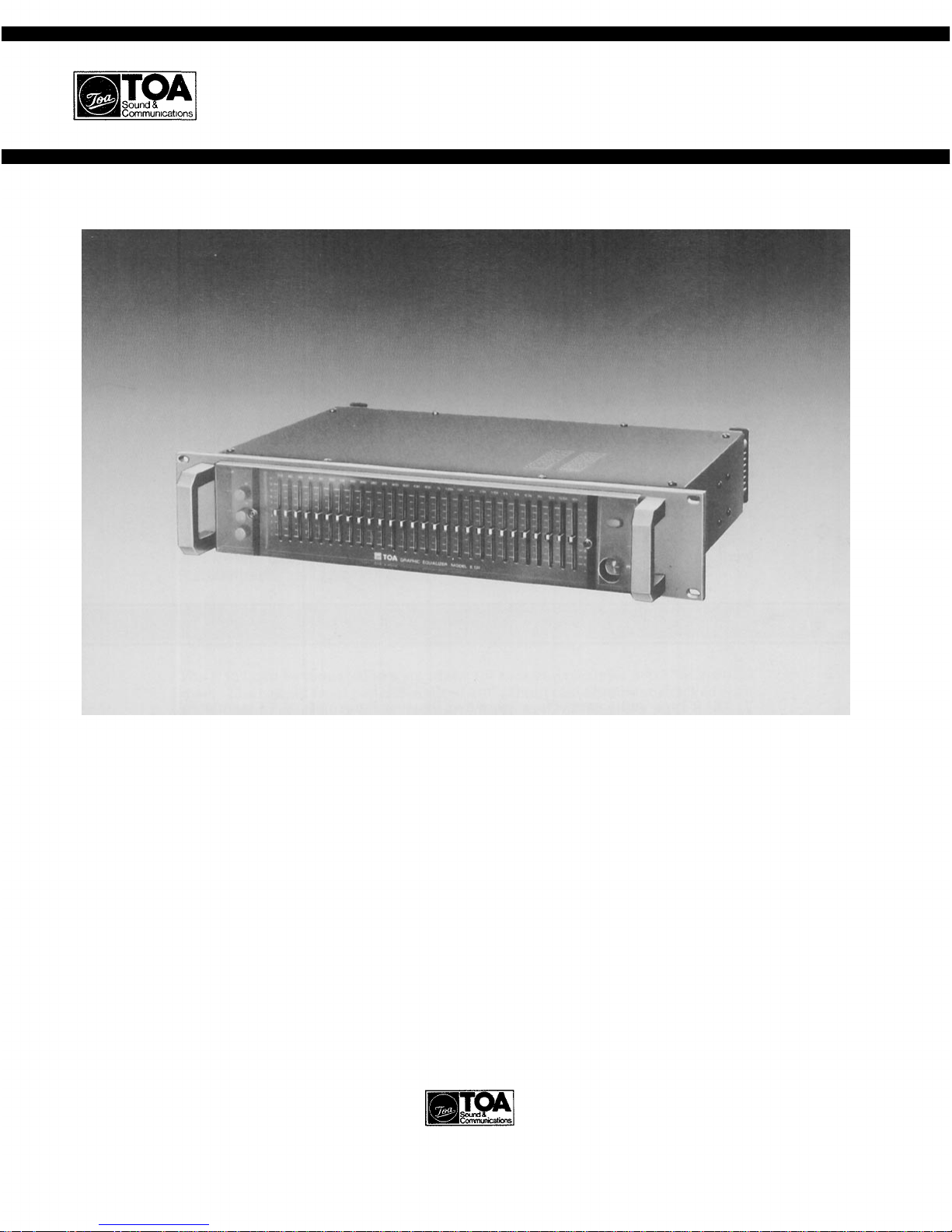
Appearance
Performance Graphs
Front Panel
Rear Panel
................................................
........................................
...................................................
.............................................
................................................
.......................................
................................................
.................................................
Input/Output Connections
Installation Precautions
Applications
............................................
....................................
..................................
1
2
2
3
3
4
5
6
7
8
9~10
Precautions
1. XLR type audio connectors are wired in accordance with NAB standards.
Pin 1 is ground (shield), pin 2 is cold (low, minus), and pin 3 is hot (high,
plus).
2. The E 131 has two versions, 120V AC operation only and 220/240V AC
operation with a voltage selector. The voltage selector on the rear panel of
the 220/240V version should be checked for proper setting prior to operation
as improper setting causes trouble. The voltage selector is set for 240V
operation at the factory.
3. Do not operate the E 131 from power mains which exceeds the indicated
mains voltage by more than 10%.
4. Do not expose the E 131 to corrosive chemicals or liquids such as soft drinks,
salt water, etc.
5. Always refer the E 131 to qualified technical service personnel. There are
no user serviceable parts inside.
- 1 -
Page 3

General Description
The TOA E 131 is a single channel, 1/3 octave active graphic equalizer designed
to allow clean, accurate audio equalization for stage, studio, or commercial
applications.
The E 131 provides 12 dB of boost or cut at each of its 28 frequencies, which are
centered at ISO 1/3 octave increments from 31.5 Hz to 16 kHz. Its signal to noise
ratio is over 120 dB making the E 131 one of the quietest equalizers on the market.
The E 131's active bandpass/bandreject filters are designed for minimum phase
shift, and feature smooth slide controls with center detents for easy and accurate
adjustment. The filters are summed in parallel for reliability, so that the failure
of one filter does not interrupt operation of the others.
In addition, continuously variable high-pass filters are provided on the front
panel. The high-pass filter has a slope of 18 dB per octave and is variable from 15
Hz to 120 Hz, while the low-pass filter has a 12 dB per octave slope and is
variable from 8 kHz to 25 kHz.
An input level control on the E 131 gives 12 dB of adjustment to allow a wide
variety of input sources. An LED indicator illuminates when either the input or
the output comes within 6 dB of clipping. In addition to the usual EQ in/out
switch, an automatic EQ bypass function provides complete equalization
bypass in the event of loss of AC power, and an output muting function
suppresses turn-on/turn-off transients.
A smoked plastic security cover is included with the E 131 to guard against
accidental disturbance, or intentional tampering when used in fixed
installations.
Inputs and outputs are transformer-isolated and balanced, with both XLR and
1/4" stereo phone jacks. Ground lift switches are provided at both inputs and
outputs to reduce hum and prevent ground loops.
The E 131 can be mounted in a standard 19" rack and occupies 3-1/2" of vertical
space. The rugged front panel is made of 1/8" (3mm) cast aluminum, backed with
a 1/8" (3mm) steel liner for added durability.
Features
1. 28 filters on ISO 1/3 octave center frequencies
from 31.5 Hz to 16 kHz.
2. 12 dB boost or cut at each center frequency,
continuously variable.
3. Signal to noise ratio greater than 120 dB.
4. High quality, low phase-shift active filters.
5. Precision calibrated, noiseless slide controls
with center detent.
6. Equalizer In/Out switch.
7. Continuously variable high- and low-pass
filters.
8. LED peak indicator to detect clipping at input
or output levels.
9. Variable input level control to accept variety
of input sources.
10. Automatic EQ bypass circuitry.
11. Transformer-isolated balanced inputs and
outputs with XLR connectors and phone
jacks.
12. Ground lift switches on input and output.
13. Smoked, plastic security cover is included.
14. Heavy aluminum die-cast front panel, stand-
ard 19" rack mountable.
- 2 -
Page 4

Specifications
Frequency Response
±ldB, 20Hz to 20kHz
Total Harmonic Distortion
Less than 0.2% at 1kHz, all sliders at 0 position, rated
output
Equalization Center Frequencies
31.5Hz to 16kHz
31.5Hz, 40Hz, 50Hz, 63Hz, 80Hz, 100Hz, 125Hz, 160Hz,
200Hz, 250Hz, 315Hz, 400Hz, 500Hz, 630Hz, 800Hz, 1kHz,
1.25kHz, 1.6kHz, 2kHz, 2.5kHz, 3.15kHz, 4kHz, 5kHz,
6.3kHz, 8kHz, 10kHz, 12.5kHz, 16kHz
Rated Input Level
+4dB (INPUT LEVEL CONTROL set for 0 position)
Rated Output Level
+4dB with 600-ohm load
Maximum Input Level
+24dB at 1kHz
Maximum Output Level
+24dB with 600-ohm load
Input Impedance
10k ohms (balanced)
Output Impedance
600 ohms (balanced)
Hum and Noise
-103dB (EQ in , all sli der s at 0 position, IHF-A weighted)
Input Connectors
One "female" XLR connector; pin 1 "shield", pin 2 "cold",
pin 3 "hot".
XLR is balanced and in parallel with one tip-ring-sleeve
(standard) phone jack.
Output Connectors
One "male" XLR connector; pin 1 "shield", pin 2 "cold", pin
3 "hot".
XLR is balanced and in parallel with one tip-ring-sleeve
(standard) phone jack.
Indicators
A red LED for output clipping
A green LED for equalizer IN
A green LED for power ON
Controls
Equalizer Sliders
±12dB
Input Level Control
±12dB
High Pass Filter
18dB per o c t a v e
Adjustable Cutoff Frequency: 15Hz to 120Hz
Low Pass Filter
12dB per octave
Adjustable Cutoff Frequency: 8kHz to 25kHz
AC Line Voltage
AC mains, 50Hz/60Hz
Power Consumption
14 watts
Finish
Black painting
Dimensions (W×H×D)
483X89X370 (mm)
19X3-1/2X14-1/2 (inches)
Weight
6.6kg (15 lbs)
Note: 0dB is referenced to 0.775 volts RMS.
Appearance
- 3 -
Page 5

Performance Graphs
Frequency Response
(Each slider is set at a max or min position)
Frequency Response (ex. 800Hz slider)
High pass & Low pass Filters
Frequency Response
(All sliders are set at a max position)
– 4 –
Page 6

Front Panel
Peak Indicator LED
The peak indicator LED will glow when the output level reaches 6dB below clipping. It is quite common
for the LED to flash on and off during high level operation. However, if the LED remains steadily lighted,
the input level control or the output level of associated equipment should be lowered until the LED only
flashes at the highest peaks.
High Pass Filter Control
This shelving-type filter provides an 18dB per octave rolloff between 120Hz and 15Hz. It is especially
useful for reducing stage or turntable rumble, AC hum, wind noise, and other subsonic components that
waste amplifier power and tax speakers.
Low Pass Filter Control
This is also a shelving-type filter that provides a 12dB per octave rolloff above 8kHz and up to 25kHz. Its
main purpose is to stop high frequency noise, oscillation, and certain types of RF interference from
damaging tweeters. It is also useful in reducing excessive background noise, such as that produced by old
phonograph records.
Input Level Control
This control adjusts the input gain by ±12dB to allow the use of a wide range of input sources. To insure
the best S/N ratio possible, adjust this control so that the peak LED flashes only occasionally.
Equalizer Sliders
These sliders are adjusted to tune or equalized the overall frequency response of a sound system.
Equalizer Indicator LED
The indicator LED turns on whenever the equalizer IN/OUT switch is "in".
Equalizer IN/OUT Switch
Equalizer switch puts the input signals either in circuit or out of circuit of the equalizer except high- and
low-pass filters. The "out" position provides flat audio response no matter what the position of the
equalizer sliders.
Power Indicator LED
The green LED glows when the power switch is "on".
Power Switch
Pushbutton alternately switches the AC power on and off.
Security Cover Stud Screw
The stud screws are provided to mount the smoked plastic security cover, which prevents inadvertent
control changes after all controls are properly set.
- 5 -
Page 7

Rear Panel
Power Fuse (Fuse 0.5A, 0.3A)
Fuse for 220/240V AC operation should be 0.3A and 0.5A for 120V AC.
AC Inlet
The power cord must be plugged into it.
* Power Cord Clamp
A plastic covered metal clip is provided to prevent accidental disconnection of the AC power cord.
Ground Lift Switch
The ground lift switch is effective to avoid ground loops that are often caused in connection with other
equipment and that may induce hum. Sliding the ground lift switch from a NORM position to the LIFT
position cuts ground loops and may reduce hum. For most applications it should be set to the NORM
position.
Output Connectors
The XLR output connector is balanced and is wired in parallel with the phone jack that can accept
tip/sleeve as well as a tip/ring/sleeve type of plug. The output impedance is 600 ohms.
Input Connectors
The XLR input connector is balanced and is wired in parallel with the phone jack that can accept
tip/sleeve as well as a tip/ring/sleeve type of plug. The input impedance is 10k ohms.
- 6 -
Page 8

Input / Output Connections
Mixing Console (RX-7)
E 131 (L)
E 131 (R)
Power Amplifier
(P
150D)
Speaker System
(38-SD×2)
- 7 -
Page 9

Installation Precautions
Ground Loops
In any audio system, there are numerous ways by which ground loops can be created. For example,
they may occur when the E 131 is mounted in a rack cabinet, or through AC ground when the E 131 is
connected with preamps, mixers, etc. These ground loops may cause hum and noise if care is not
taken during connection. An increase in noise from ground loops may be minimized by breaking the
ground loop. Generally, the chassis ground of the signal line should be broken as shown below.
Main AC Ground
Rack cabinet
When a Y cord is used, shorten the wiring to minimize noise.
Ground lift switches are provided on the rear of the E 131. Sliding the ground lift switch from a
NORM position to the LIFT position lifts ground.
On the road use
The E 131 is sturdily constructed with an aluminum die-cast front panel that is reinforced by means
of an iron plate attached to its back. To ensure that strength is maintained during its transportation
from one place to another, however, you should also reinforce the unit from the back of the rack with
a special support bracket. This can be accomplished by removing cord-hangers on the rear panel, and
screws that hold the rear panel to chasis, and fitting the special support brackets through the holes.
Top view
Special support bracket
Side view
- 8 -
Page 10

Applications
Feedback Prevention
When the overall gain of a sound system is increased,
feedback will occur at frequencies where the system response
has peaks. Suppose the system has an uneven frequency
response like that shown in the following diagram. The
frequency at which feedback will occur when gain is
increased is about 500Hz. In this case, feedback may be
Room Equalization
In a sound reinforcement system for a room, the clarity of
sound can be adversely affected by the room frequency
response including standing waves (room resonances),
reflections of sound, and relations between direct and
indirect sound.
prevented by attenuating levels at 500Hz by 3dB to 5dB with
the E131. If the overall gain is again gradually increased,
feedback will occur next at about 125Hz. It ma y be st opped by
attenuating the levels 2dB to 3dB at that frequency. In this
procedure, sufficient gain in the sound system is obtained
before feedback.
The E 131 is an effective tool to equalize the room frequency
response to a flat response and improve sound clarity.
For example, suppose that there is a room frequency response
as shown below.
Level
Pressure
Sound
The equalizer sliders are set as shown below.
The overall response after equalization will then be as
follows.
Before equalization
Frequency
Frequency response
of equalizer
Frequency response
after equalization
Level
Pressure
Sound
Frequency
- 9 -
Page 11

Applications
Equalization for music
The Graphic Equalizer is designed not only for use in preventing feedback and equalizing
uneven room frequency response to be flat, but also for equalizing frequency response to
your tastes and producing favourable sound for you. Fig. 1 shows each frequency band
and its corresponding auditory feeling. Fig. 2 and table 1 show the relation between each
musical instrument and its frequency band. They can be of great help in the equalizer
operation. (They are referenced from a book entitled "Practical Guide for concert")
EQUALIZATION CHART
These sounds
are felt more
than really
heard. They
give a sense of
power. Too
much produces
a muddy sound.
INSTRUMENT CHART
The rythm section
appears here. Either
a fat or thin sound
can be heard by
mis-EQ here. Too
much becomes
boomy. Bass guitarSnare-Toms.
Probably the most important of all. Most all
instruments contain harmonics here.
300Hz boosting can cause
horn like sounds. 1k to 2k
sounds tinny. Too much
here sounds like the telephone.
INSTRUMENT EQUALIZATION CHART
Acoustic guitar
Electric guitar
Bass guitar
Human voice
Piano (Acoustic)
Piano (Electric)
Figure 1
Upper vocal region. Too
much here will cause
great fatigue, and loose
speech intelligence. Reducing 3k can bring
vocals on top.
Bass strings resonate between 70 to 120Hz, body
around 300Hz. Avoid boosting these to stop feedback.
3kHz and 5kHz gives great "clarity".
Resonances differ — depending on type. Good full
sounds around 300 to 500Hz. Clarity at 3kHz.
Extreme lows are at 60 to 90Hz. "Pick" or "pluck"
sounds are around 800 to 1200Hz. Upper harmonics
clarified about 3kHz.
Good fu lln ess at 150Hz. Watch for "boominess" around
250Hz. Mid-range 10kHz.
Bass strings responate around 100Hz. Watch for sub-
harmonics at 30 to 50Hz.
Good mid-clarity at 3kHz to 5kHz thins out rapidly in
high end. Be careful around 1.5kHz to 2.5kHz to avoid
the "bar room sound".
Presence range. Great
achievement in overall level can be had
here. Too little causes
a "far away" sound.
Sibilance levels
can be controlled here. Bright,
clean definition.
Organ
Violin
Brass instruments
Bass drum
Snare drum
Tom Tom
Floor Tom
Hi Hat
Cymbal overhead
Talk Box
- 10
-
Usually dies under 200Hz. Has great mid-sounds
around 1200 to 2000Hz. Top end cuts off at 6kHz.
Rich ful lne ss at 400Hz. Natu ral mids around 1500 to
2500Hz. Avoid "scratch" sounds at 8kHz.
Watch for "hot" mids around 2kHz. Low end boost
around 400Hz. Top end clarity at 6kHz.
Great low "kick" at 40Hz. The mids at 2kHz gives the
familiar "punch".
Good ful lness at 100Hz. The "crack" is boosted at 2kHz.
real easy. The snares extend to above 4kHz.
The main fullness is around 200Hz. The mid punch
extends to 4kHz.
Same as tom, but extends down to 80Hz.
Wa tch for the "gong" sound around 300Hz. Good
"shimmer" sounds are around 8kHz to 10kHz.
About the same as hi-hat only has more low end around
150Hz.
Depending on the guitar sound driving it and the resonance of each player's mouth, should have great "bite"
around 1200Hz and dies above 6kHz.
Page 12

TO A ELECTRIC CO., LTD.
KOBE, JAPAN
Printed in Japan
133-02-674-8
 Loading...