

Toa DT-E70 Installation Manual
TOA INTERCOM SYSTEM
INSTALLATION MANUAL
DATA TRANSMITTING UNIT
DT-E70
Please follow the instructions in this manual to obtain the optimum results from this unit.
We also recommend you to keep this manual handy for future reference.
TOA Corporation
CONTENTS
General
description ......................................................................................................................... 3
Part description ............................................................................................................................. 4
Channel
selector
switch
setting ....................................................................................................... 4
Installation ................................................................................................................... 5
Connection ................................................................................................................. 6~7
Time
setting
YC-900
.........................................................................................................
8~9
connection ................................................................................................................ 10~11
Specifications ................................................................................................................................ 12
Accessories
.........................................................................................................
12
GENERAL DESCRIPTION
The DT-E70 Data Transmitting Unit is designed for exclusive use with the TOA EXES-6000 series
exchanges. Functions made available from this unit when used in conjunction with the DR-B61 Data
Receiving Unit and the HF-250M Intercom Station with a display include In/Out Annunciation and Calling
Party Indication capabilities. The unit can be used fro both desk-top and rack-mounted applications.
- -
-3-

PART DESCRIPTION
[Front view] [Rear view]
Release knob
Switch cover
Data output connector (CN3) f or HF-250M
Data input connector (CN2)
Data input connector (CN1)
Data output terminal for DR-B61
Power input terminal
CHANNEL SELECTOR SWITCH SETTING
Pull the release knob forward to remove the switch cover, and the channel selector switch can be seen. Set
the channel selector according to the functions. Refer to the "EX-600 and CP-66 Installation Hand Books" for
the functions of each channel.
-4-
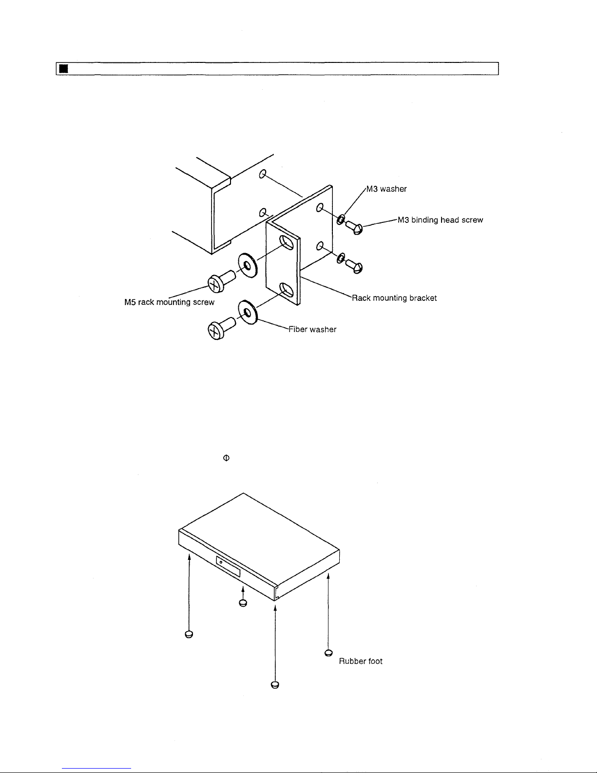
INSTALLATION
1. Rack mounting applications
Using the supplied brackets, mount the unit in the rack.
Note : The DT-E70 unit can not be mounted in the EX-610/620 exchanges. Mount it using the optional
CR-271N or CR-392N cabinet rack.
2. Desk top applications
Attach supplied rubber feet to holes (
2.5mm) in the bottom surface (four places).
-5-
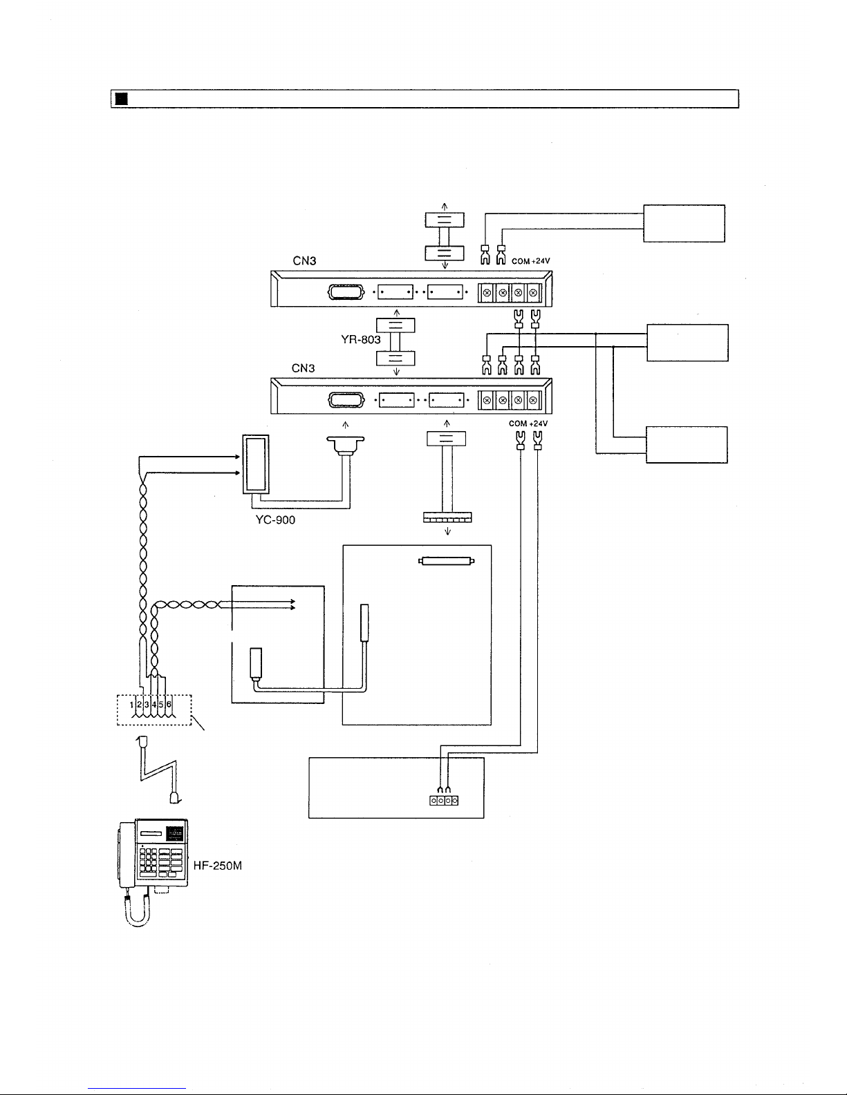
CONNECTION
To other DT-E70 units
DR-B61 unit
DR-B61 unit
DR-B61 unit
YR-802
or YR-806
Twisted paired cable
BX-610/620
Terminal box
Twisted paired cable
6-pin modular jack type rosette
(4-conductor)
HF-250M's
modular plug cord
Interface connector
EXES-6000 series
exchange
YR-810
or YR-801
24V DC power supply
[AD-242A (2.5A)]
[ Rear cover wiring example ]
-6-
1. Connect between the exchange and the data transmitting unit using the YR-806 cable (1m in length).
When the unit is placed on the EX-610 or 620 exchange, use the YR-802 cable (0.4m).
2. For connection between the exchange and the terminal box, use the YR-810 cable (for station) or the
YR-801 cable (for paging or tie-line unit).
3. When installing additional data transmitting units, use the YR-803 cable.
4. CN1 or CN2 connector may be used for connection because both connectors are internally parallel-
connected.
5. Use the 24V DC power supply having the current capacity of 0.2A per unit. If only one unit is used, the
power can be provided from the exchange's 24V output.
6. Use the shielded or twisted paired cable for connection between the data transmitting unit and the
DR-B61 data receiving unit.
7. Turn the power on for the data transmitting unit before the exchange. When turning the power off, first
set the exchange power switch to OFF.
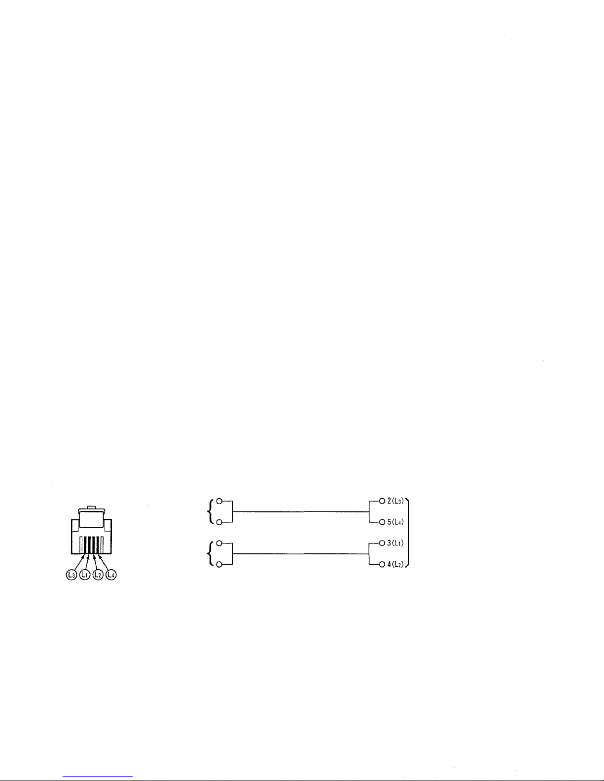
8. Using the commercial 6-pin modular jack type rosette (4-conductor), connect HF-250M's modular plug
cord L1 and L2 to the BX-610 or BX-620 terminal box, and L3 and L4 to the optional YC-900 terminal
box.
[Front view]
[YC-900]
[BX-610/620]
HF-250M's modular plug cord
Note : Remove the front and top panels to connect the EX-600 and the YR-806.
Data line
Intercom line
-7-
6-pin modular jack type
rosette (4-conductor)
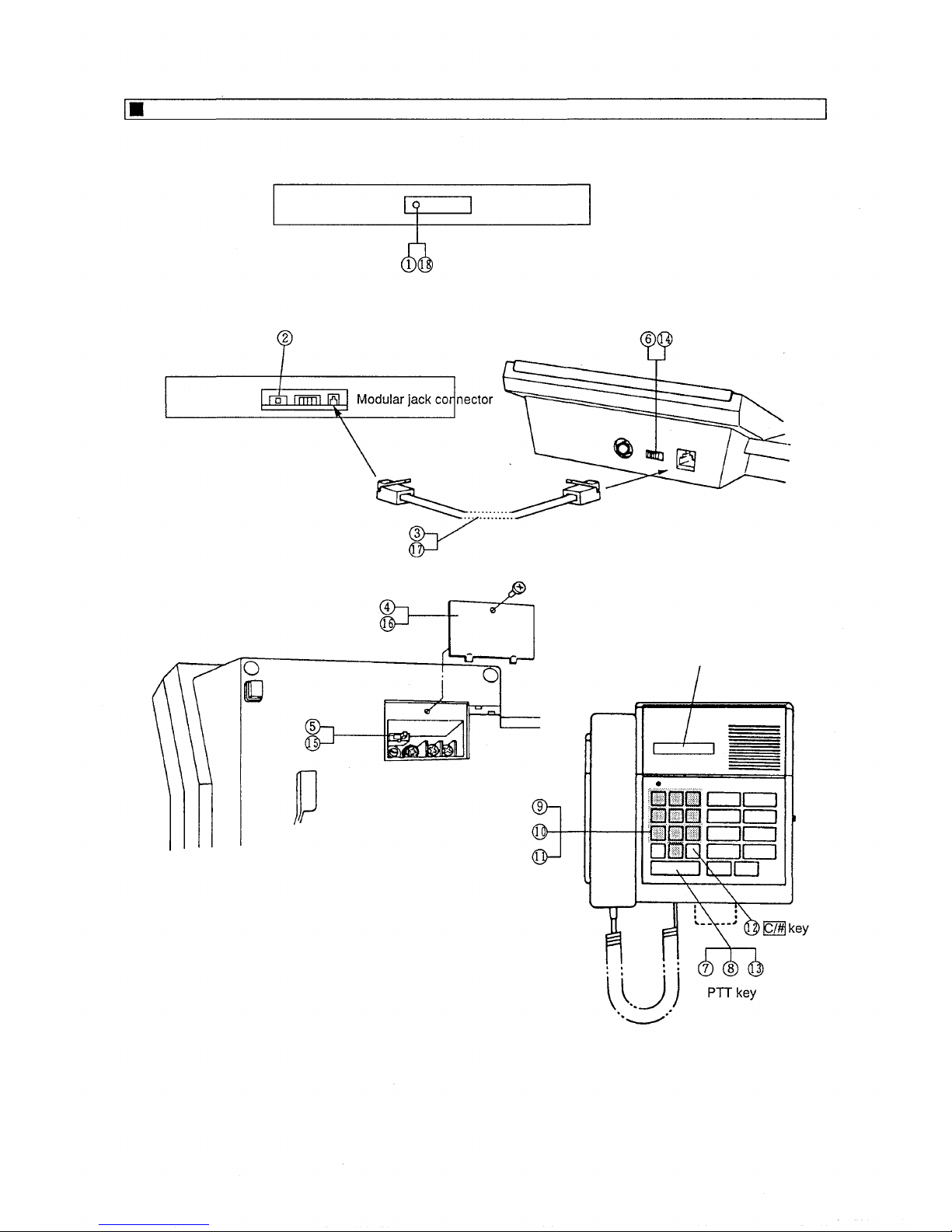
TIME SETTING
Register the time to be displayed on the HF-250M's liquid crystal display into the DT-E70 unit.
[Front view of DT-E70E]
Release knob
Switch cover
[REGISTER] switch
Time data backup switch
[Rear Inside view of DT-E70E]
[Top vie w of HF-250M]
HF-250M's Modular plug cord
(6-pin 4-conductor modular plug cord)
Terminal cover
TX switch
[Bottom view of HF-250M]
Liquid crystal display (LCD)
Dial keys
[Front view of HF-250M]
-8-
 Loading...