

Page 1
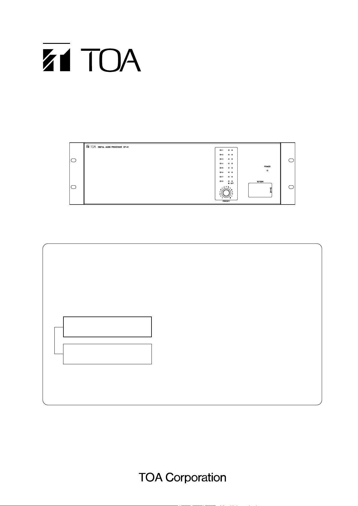
OPERATING INSTRUCTIONS
DIGITAL AUDIO PROCESSOR DP-K1
Thank you for purchasing TOA's Digital Audio Processor.
Please carefully follow the instructions in this manual to ensure long, trouble-free use of your equipment.
The various signal processing functions that the DP-K1 can implement are set using the supplied
setting software.
The manual operation at the DP-K1 is only to recall the programmed setting state (preset memory)
and to lock/unlock the knob to prevent accidental wrong operation.
For detailed descriptions of each function and its setting procedure, read the software setting
instruction manual included in the supplied CD.
[Instruction manual configuration]
Operating Instructions
(this book)
Describes how to operate, install, and connect the DP-K1.
Software Setup Manual
(included in the supplied CD)
Describes the details of signal processing functions and
how to set the functions using the setting software, and
update the firmware.
Note: This book supports the following software versions.
Firmware: Version 2.00 or later
DP-K1 setting software: Version 2.00 or later
Page 2

2
TABLE OF CONTENTS
1. SAFETY PRECAUTIONS ................................................................................ 4
2. GENERAL DESCRIPTION .............................................................................. 5
3. FEATURES ........................................................................................................... 5
4. HANDLING PRECAUTIONS ........................................................................... 5
5. NOMENCLATURE AND FUNCTIONS
5.1. DP-K1 Digital Audio Processor
[Front] ................................................................................................................. 6
[Rear] .................................................................................................................. 7
5.2. Optional Modules
5.2.1. D-921F Microphone/Line Input Module ................................................ 8
5.2.2. D-921E Microphone/Line Input Module ............................................... 8
5.2.3. D-922F Microphone/Line Input Module ................................................ 9
5.2.4. D-922E Microphone/Line Input Module ................................................ 9
5.2.5. D-936R Stereo Input Module ................................................................ 9
5.2.6. D-923AE Digital Input Module ................................................................ 10
5.2.7. D-937SP Digital Input Module ................................................................ 10
5.2.8. D-971M Line Output Module ................................................................ 10
5.2.9. D-971E Line Output Module ................................................................ 11
5.2.10. D-971R Line Output Module ................................................................ 11
5.2.11. D-972AE Digital Output Module ............................................................. 11
5.2.12. D-961SP Digital Output Module ............................................................. 12
5.2.13. D-981 Remote Control Module ......................................................... 12
5.2.14. D-983 Remote Control Module .......................................................... 12
6. SIGNAL PROCESSING FUNCTIONS ........................................................ 13
7. OPERATIONS
7.1. Recalling the Preset Memory ............................................................................ 13
7.2. Locking and Unlocking the Preset Knob ........................................................... 13
8. PC CONNECTIONS
8.1. Connections ...................................................................................................... 14
8.2. Repositioning the Network Connection Terminal .............................................. 15
9. RESTORING FACTORY DEFAULT SETTING ......................................... 17
10. RACK MOUNTING ............................................................................................ 17
11. CONNECTIONS
11.1. Connection Example ....................................................................................... 18
11.2. Removable Terminal Plug Connection ............................................................ 19
11.3. Ferrite Cable Clamp Attachment (For D-972AE only) ..................................... 19
12. BLOCK DIAGRAM ............................................................................................ 20
Page 3

3
13. LEVEL DIAGRAMS
13.1. Analog Input/Output ........................................................................................ 22
13.2. Digital Input/Output ......................................................................................... 22
14. SPECIFICATIONS
14.1. DP-K1 Digital Audio Processor .................................................................. 23
14.2. D-921F Microphone/Line Input Module (Optional) ...................................... 24
14.3. D-921E Microphone/Line Input Module (Optional) ...................................... 24
14.4. D-922F Microphone/Line Input Module (Optional) ...................................... 24
14.5. D-922E Microphone/Line Input Module (Optional) ...................................... 25
14.6. D-936R Stereo Input Module (Optional) ...................................................... 25
14.7. D-923AE Digital Input Module (Optional) ....................................................... 25
14.8. D-937SP Digital Input Module (Optional) ....................................................... 25
14.9. D-971M Line Output Module (Optional) ....................................................... 26
14.10. D-971E Line Output Module (Optional) ....................................................... 26
14.11. D-971R Line Output Module (Optional) ....................................................... 26
14.12. D-972AE Digital Output Module (Optional) .................................................... 26
14.13. D-961SP Digital Output Module (Optional) .................................................... 27
14.14. D-981 Remote Control Module (Optional) ................................................. 27
14.15. D-983 Remote Control Module (Optional) ................................................. 28
Page 4
4
When Installing the Unit
• Do not expose the unit to rain or an environment
where it may be splashed by water or other liquids,
as doing so may result in fire or electric shock.
• Use the unit only with the voltage specified on the
unit. Using a voltage higher than that which is
specified may result in fire or electric shock.
• Do not cut, kink, otherwise damage nor modify the
power supply cord. In addition, avoid using the
power cord in close proximity to heaters, and never
place heavy objects -- including the unit itself -- on
the power cord, as doing so may result in fire or
electric shock.
When the Unit is in Use
• Should the following irregularity be found during
use, immediately switch off the power, disconnect
the power supply plug from the AC outlet and
contact your nearest TOA dealer. Make no further
attempt to operate the unit in this condition as this
may cause fire or electric shock.
· If you detect smoke or a strange smell coming
from the unit.
· If water or any metallic object gets into the unit
· If the unit falls, or the unit case breaks
· If the power supply cord is damaged (exposure of
the core, disconnection, etc.)
· If it is malfunctioning (no tone sounds.)
• To prevent a fire or electric shock, never open nor
remove the unit case as there are high voltage
components inside the unit. Refer all servicing to
your nearest TOA dealer.
• Do not place cups, bowls, or other containers of
liquid or metallic objects on top of the unit. If they
accidentally spill into the unit, this may cause a fire
or electric shock.
When Installing the Unit
• Never plug in nor remove the power supply plug
with wet hands, as doing so may cause electric
shock.
• When unplugging the power supply cord, be sure
to grasp the power supply plug; never pull on the
cord itself. Operating the unit with a damaged
power supply cord may cause a fire or electric
shock.
• Do not block the fan exhaust vent on the unit's rear
and the ventilation slots on the bottom. Doing so
may cause heat to build up inside the unit and
result in fire.
• Avoid installing the unit in humid or dusty locations,
in locations exposed to the direct sunlight, near the
heaters, or in locations generating sooty smoke or
steam as doing otherwise may result in fire or
electric shock.
• Be sure to follow the instructions below when rackmounting the unit. Failure to do so may cause a fire
or personal injury.
· Install the equipment rack on a stable, hard floor.
Fix it with anchor bolts or take other arrangements
to prevent it from falling down.
· Use the screws supplied with the unit to mount on
TOA's rack.
· When connecting the unit's power cord to an AC
outlet, use the AC outlet with current capacity
allowable to the unit.
• Do not connect the 10/100M terminal with any
cables such as a telephone line that may cause
excessive voltage.
When the Unit is in Use
• Switch off the power, and unplug the power supply
plug from the AC outlet for safety purposes when
cleaning or leaving the unit unused for 10 days or
more. Doing otherwise may cause a fire or electric
shock.
1. SAFETY PRECAUTIONS
• Before installation or use, be sure to carefully read all the instructions in this section for correct and safe
operation.
• Be sure to follow all the precautionary instructions in this section, which contain important warnings and/or
cautions regarding safety.
• After reading, keep this manual handy for future reference.
Safety Symbol and Message Conventions
Safety symbols and messages described below are used in this manual to prevent bodily injury and property
damage which could result from mishandling. Before operating your product, read this manual first and
understand the safety symbols and messages so you are thoroughly aware of the potential safety hazards.
Indicates a potentially hazardous situation which,
if mishandled, could result in death or serious
personal injury.
WARNING
Indicates a potentially hazardous situation which,
if mishandled, could result in moderate or minor
personal injury, and/or property damage.
CAUTION
Page 5

5
2. GENERAL DESCRIPTION
The TOA DP-K1 is a 3U rack mountable Digital Audio Processor.
It features an Automatic Resonance Control function that automatically generates an optimum filter curve to
improve sound clarity after measuring the acoustic characteristics in architectural space.
All of this function and other acoustic signal processing functions such as compressor and delay are set by a
PC using the supplied setting software.
The settings can be stored in the unit's internal memory and the stored settings can be recalled from the unit
without connecting the PC.
The setting software is included in the supplied CD-ROM or can be downloaded from our website at
http://www.toa-products.com/.
3. FEATURES
• Acoustic control that improves sound clarity can be attained through simple operation.
• Signals are digitally processed, ensuring high-accuracy sound parameter settings.
• Modular construction permits flexible configuration of inputs and outputs, from 2-IN/4-OUT to 8-IN/8-OUT
systems.
• Because 8 memories are built inside, stored data can be easily recalled without connecting a PC after
setting completion.
• The preset knob-lock function prevents trouble resulting from wrong operation.
4. HANDLING PRECAUTIONS
• The supplied power supply cord is designed for exclusive use with the unit. Never use it with other
equipment.
• Use the unit in locations where the temperature is between +5°C to +40°C (no condensation) and the
humidity is less than 90%.
• The DP-K1 is a precision audio component. To prevent failure, avoid locations where the unit may be
exposed to strong shocks or vibrations.
• To clean, be sure to first switch off the power, then wipe with a dry cloth. When extremely dirty, use a soft
cloth dampened in neutral detergent. Never use benzene, thinner or chemically-treated towels, which may
damage the unit's finish.
Page 6
6
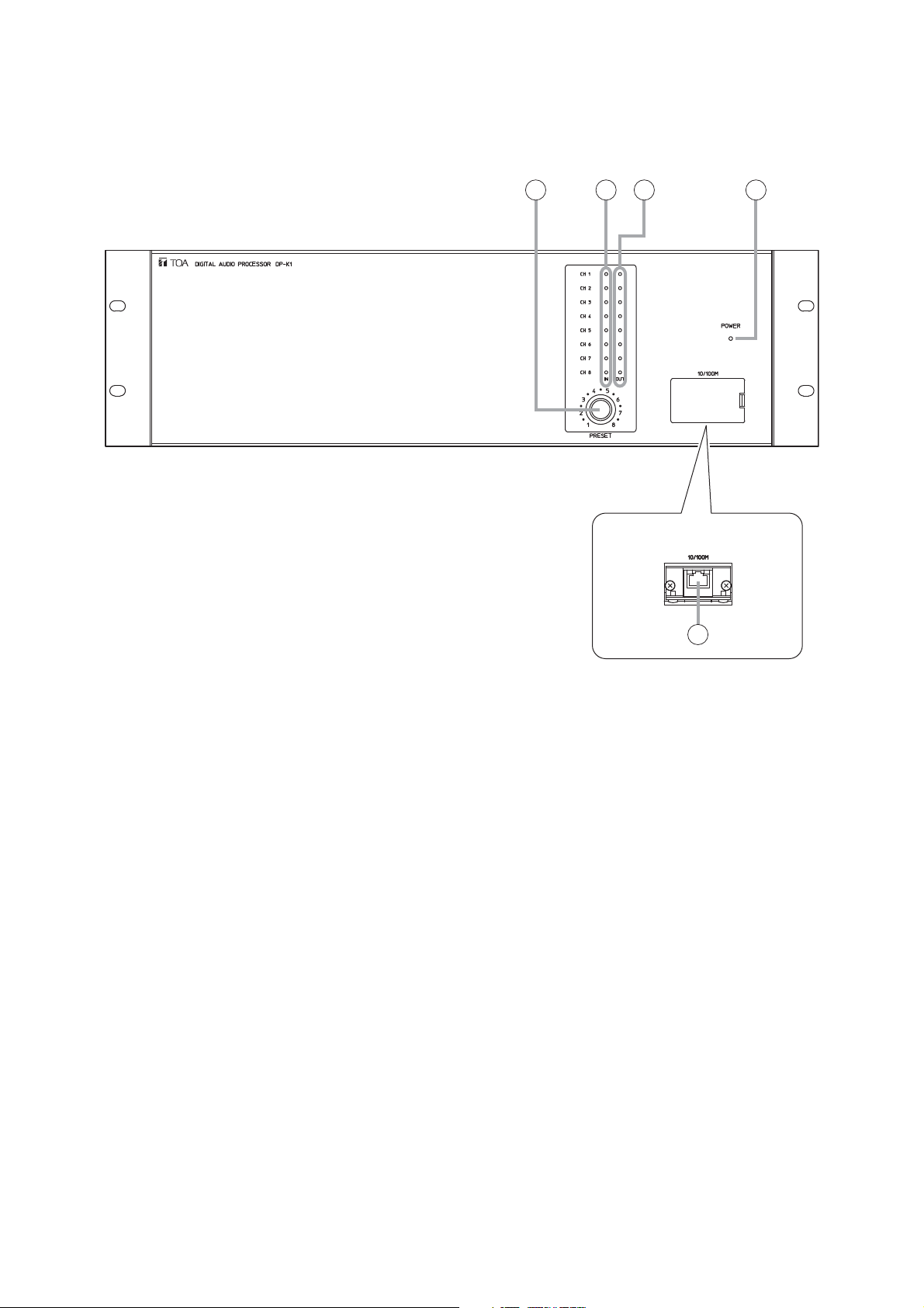
5. NOMENCLATURE AND FUNCTIONS
5.1. DP-K1 Digital Audio Processor
[Front]
1. Power lamp
Lights when the power switch is set to ON.
2. Preset knob
Rotating this knob recalls the preset memory.
Holding down it for 5 seconds or more locks or
unlocks the knob.
The numbers and dots marked around the knob
are LED indicators. They indicate the currently
recalled memory number or communication state
between the DP-K1 and the PC. For details, refer
to p. 13 and 14.
3. Input channel indicators
Each indicator lights green when an input signal
level is –40 dB or higher on the basis of the rated
level.
4. Output channel indicators
Each indicator lights green when an output signal
level is –40 dB or higher on the basis of the rated
level.
5. Network connection terminal
Connects to 10 Base-T/100 Base-TX networks.
(RJ45 Ethernet jack)
When connecting the unit to a switching hub, use
a UTP Category 5 straight through cable fitted with
RJ45 connectors.
When connecting the unit to a PC directly, use a
UTP Category 5 cross cable fitted with RJ45
connectors.
Note
You can reposition this terminal to the rear panel.
(Refer to the next page, No. 9 "Network
connection terminal panel.")
12 3 4
[Inside of the pocket cover]
5
Page 7
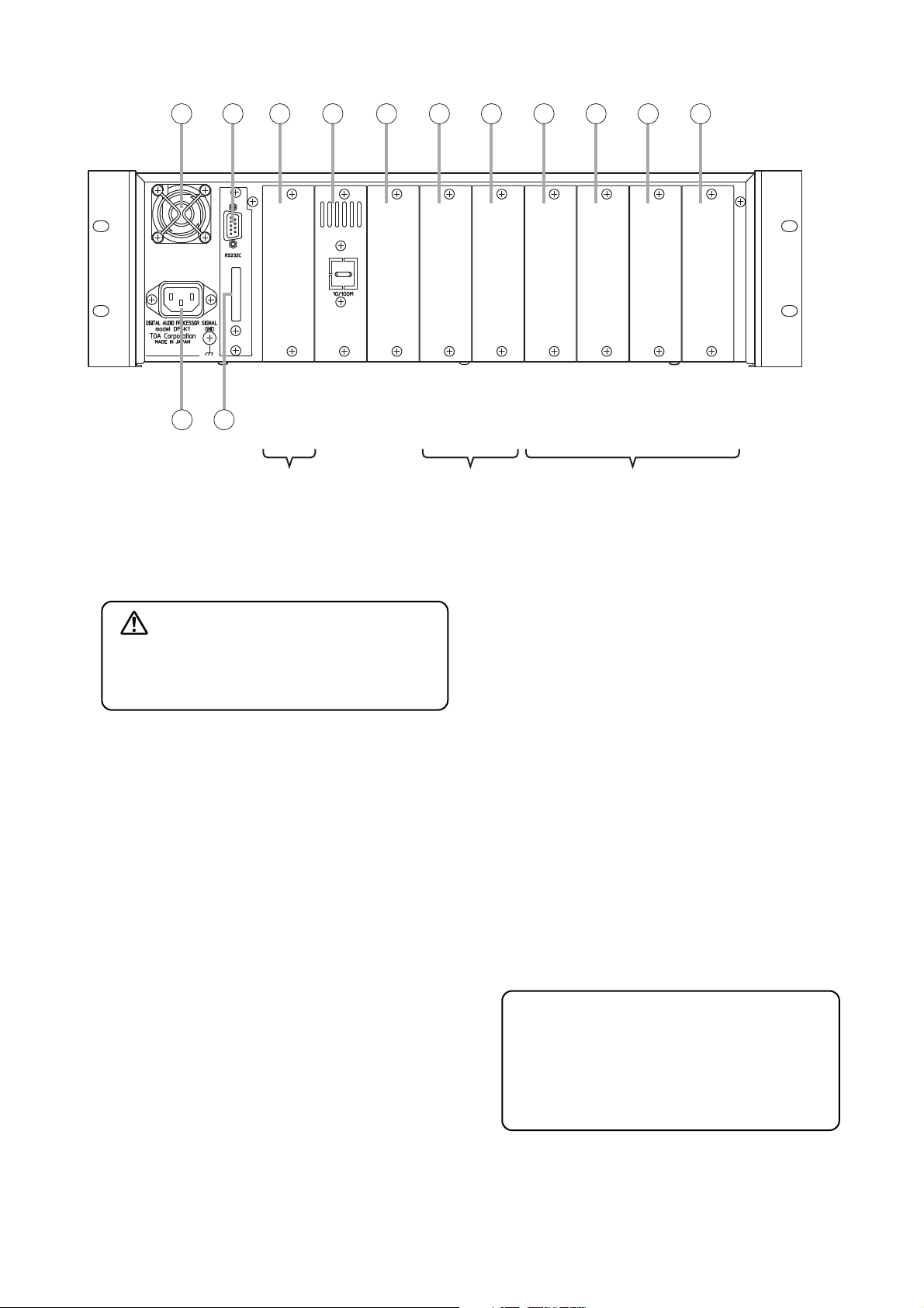
6. Cooling Fan
7. RS-232C Communication Port
The port is solely for the maintenance use.
8. Remote Control Module Slot
The remote control module's dedicated slot.
9. Network connection terminal panel
The blank panel is attached to the unit as shipped
by the factory.
You can remove the network connection terminal
from the front panel, and attach it to this panel.
For repositioning the terminal from the front panel,
refer to p. 15.
10. Empty slot
Unused slot
11. Output module slot
Slot for output channels 5 – 8.
12. Output module slot
Slot for output channels 1 – 4.
13. Input module slot
Slot for input channels 7 and 8.
14. Input module slot
Slot for input channels 5 and 6.
15. Input module slot
Slot for input channels 3 and 4.
16. Input module slot
Slot for input channels 1 and 2.
17. AC inlet
Connect this inlet to the wall AC outlet using the
supplied power cord.
18. MAC address
A 12-digit hexadecimal network address peculiar
to the unit.
7
[Rear]
CAUTION
Do not block the fan exhaust vent. Doing so
may cause heat to build up inside the unit and
result in fire.
The MAC address is used to make the unit's
network setting.
Record it for later reference.
For network setting procedures, refer to the
software setting instruction manual included
in the supplied CD.
6 7 8 9 10 11 12 13 14 15 16
00-40-9D-26-14-58
17
18
Outputs
5 – 8
Outputs
1 – 4
Inputs
7 & 8
Inputs
5 & 6
Inputs
3 & 4
123456789
Inputs
1 & 2
Slot number
Input & output
channel
Remote control module slot
Output module slot
Input module slot
Module type
Page 8
8
5.2. Optional Modules
Notes
• Make sure that the power is switched OFF before attaching or detaching modules.
• To avoid failures due to static electricity, do not touch the parts or terminals on the circuit board of both the
unit and module.
• Ensure that the module is installed and secured with screws in the correct position.
• Cover idle slots with the blank panels attached to the unit as shipped by the factory.
• Two silver slotted screws at the top and bottom of the front panel are handles used for module detachment.
Never rotate them because they do not function as screws.
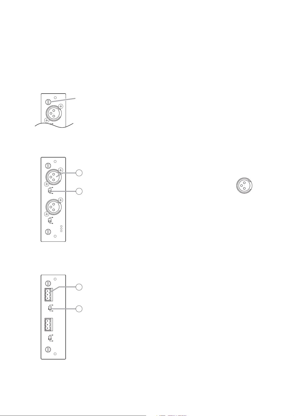
5.2.1. D-921F Microphone/Line Input Module
1. Monaural Input Terminal [1, 2] (XLR-3-31 equivalent)
Electronically-balanced input terminal. (Pin 1:
Ground; Pin 2: Hot; Pin 3: Cold)
Use XLR-3-12C or equivalent for connection.
Input sensitivity (–50/–36/–10/+4 dB) and
phantom power (+15 V) ON/OFF can be set by
a PC using the setting software supplied with
the DP-K1.
2. Ground Lift Switch [GND LIFT/NORMAL]
Hum noise may be generated due to ground loops created when the unit
is connected to other equipment. Setting the switch to the GND LIFT
position cuts the ground loop.
5.2.2. D-921E Microphone/Line Input Module
3. Monaural Input Terminal [1, 2]
Electronically-balanced, removable terminal block. (H: Hot; C: Cold; E:
Ground)
Input sensitivity (–50/–36/–10/+4 dB) and phantom power (+15 V)
ON/OFF can be set by a PC using the setting software supplied with the
DP-K1.
4. Ground Lift Switch [GND LIFT/NORMAL]
Hum noise may be generated due to ground loops created when the unit
is connected to other equipment. Setting the switch to the GND LIFT
position cuts the ground loop.
Note
Be sure to use the supplied removable terminal plugs (3P) for
connection.
MIC/LINE INPUT MODULE
GND LIFT
Handle
1
MIC/LINE INPUT MODULE [–50 / –36 / –10 / +4 dB] model D-921F
GND LIFT
NORMAL
1
1
2
GND LIFT
NORMAL
ACCESSORY I.T.E 78CK
2
1
: E
: H
2
: C
3
2: Hot
3: Cold
1: Ground
MIC/LINE INPUT MODULE [–50 / –36 / –10 / +4 dB] model D-921E
E
C
H
GND LIFT
NORMAL
E
C
H
GND LIFT
NORMAL
3
1
4
2
ACCESSORY I.T.E 78CK
Page 9
9
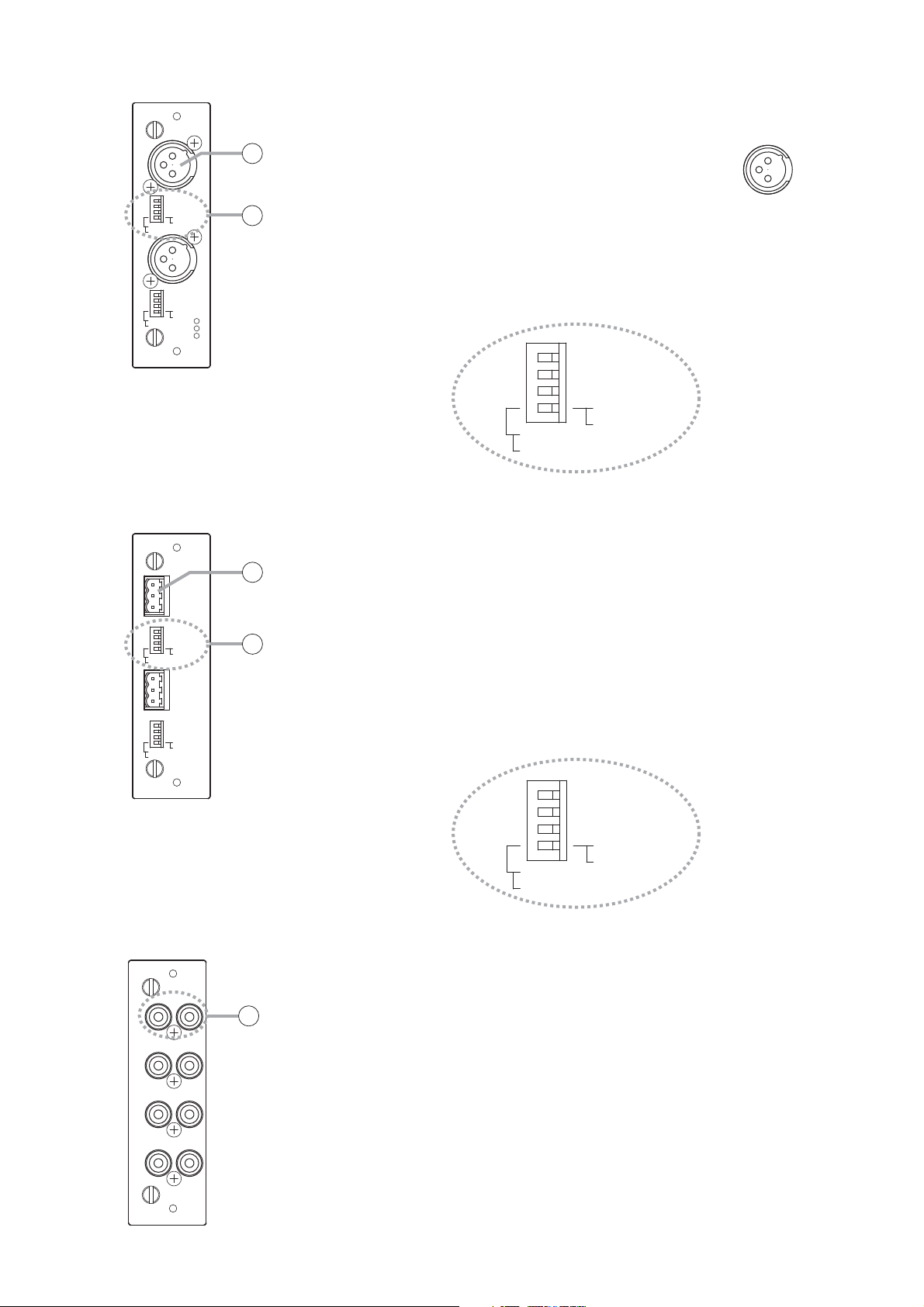
5.2.4. D-922E Microphone/Line Input Module
7. Monaural Input Terminal [1, 2]
Electronically-balanced, removable terminal block. (H: Hot; C: Cold; E:
Ground)
Note
Be sure to use the supplied removable terminal plugs (3P) for
connection.
8. Input Sensitivity Switch [PHANTOM, GND LIFT, MIC/LINE]
4-pole switch. Enables phantom power (+15V; ON/OFF, enabled only
when set to the MIC position), ground lift and input sensitivity.
Input sensitivity: –36 or –50 dB (MIC mode) / –10 or +4 dB (LINE mode)
5.2.5. D-936R Stereo Input Module
9. Stereo Input Terminal [1L/1R, 2L/2R, 3L/3R, 4L/4R]
Unbalanced, RCA pin jack stereo input terminals. Either a single stereo
input can be selected from the 4 available stereo inputs or all 4 stereo
channels can be mixed.
Mode setting and stereo selection are performed by a PC using the
setting software supplied with the DP-K1. They can also be remotely
selected by way of connected external equipment through the use of the
control module.
Input signal level: –10 dB
5.2.3. D-922F Microphone/Line Input Module
5. Monaural Input Terminal [1, 2] (XLR-3-31 equivalent)
Electronically-balanced input termfinal. (Pin 1:
Ground; Pin 2: Hot; Pin 3: Cold)
Use XLR-3-12C or equivalent for connection.
6. Input Sensitivity Switch [PHANTOM, GND LIFT, MIC/LINE]
4-pole switch. Enables phantom power (+15 V; ON/OFF, enabled only
when set to the MIC position), ground lift and input sensitivity.
Input sensitivity: –36 or –50 dB (MIC mode) / –10 or +4 dB (LINE mode)
MIC/LINE INPUT MODULE model D-922F
ON
NORMAL
MIC
-10dB(LINE)
-50dB(MIC)
ON
NORMAL
MIC
-10dB(LINE)
-50dB(MIC)
ACCESSORY I.T.E 78CK
OFF : PHANTOM
LIFT : GND
LINE
+4dB(LINE)
-36dB(MIC)
OFF : PHANTOM
LIFT : GND
LINE
+4dB(LINE)
-36dB(MIC)
5
1
6
2
1
: E
: H
2
: C
3
MIC/LINE INPUT MODULE model D-922E
E
CH1
7
NORMAL
MIC
NORMAL
MIC
ON
-10dB(LINE)
-50dB(MIC)
ON
-10dB(LINE)
-50dB(MIC)
OFF : PHANTOM
LIFT : GND
LINE
+4dB(LINE)
-36dB(MIC)
E
C
H
OFF : PHANTOM
LIFT : GND
LINE
+4dB(LINE)
-36dB(MIC)
8
2
ON
NORMAL
MIC
OFF : PHANTOM
LIFT : GND
LINE
-10dB(LINE)
-50dB(MIC)
2: Hot
3: Cold
1: Ground
+4dB(LINE)
-36dB(MIC)
ACCESSORY I.T.E 78CK
1R2R1L
9
2L
3L3R
4L4R
model D-936RSTEREO SELECT INPUT MODULE [ –10 dB]
ACCESSORY I.T.E 78CK
ON
NORMAL
MIC
OFF : PHANTOM
LIFT : GND
LINE
+4dB(LINE)
-10dB(LINE)
-36dB(MIC)
-50dB(MIC)
Page 10

10
5.2.7. D-937SP Digital Input Module
11. Optical Input Terminal [OPTICAL, 1,2]
Optical input terminal of S/PDIF format.
12. Coaxial Input Terminal [COAXIAL 3, 4]
Coaxial input terminal of S/PDIF format.
Notes
• Use a coaxial cable with characteristic impedance of 75 Ω for
connection.
• One of four line inputs (stereo) is selected. Input selection is performed
by a PC using the setting software supplied with the DP-K1.
5.2.8. D-971M Line Output Module
13. Monaural Output Terminal [1, 2, 3, 4] (XLR-3-32 equivalent)
Electronically-balanced output terminal.
(Pin 1: Ground; Pin 2: Hot; Pin 3: Cold)
Output signal level: +4dB
Use XLR-3-11C or equivalent for connection.
5.2.6. D-923AE Digital Input Module
10. AES/EBU Digital Input Terminal [AES/EBU, 1/2]
(XLR-3-31 equivalent)
Digital input terminal of AES/EBU format.
(Pin 1: Ground; Pin 2: Signal; Pin 3: Signal)
Use the XLR-3-12C or its equivalent for
connection.
Note
Use a digital audio cable with characteristic
impedance of 110 Ω for connection.
DIGITAL IN
AES/EBU
model D-923AEDIGITAL INPUT MODULE
10
1/2
DIGITAL IN
OPTICAL
model D-937SPDIGITAL INPUT MODULE
COAXIAL
11
1
2
12
3
4
2: Signal
3: Signal
1: Ground
LINE OUTPUT MODULE
[+4 dB]
model D-971M
ACCESSORY I.T.E 78CK
13
1
2
3
4
1
: E
: H
2
: C
3
2: Hot
3: Cold
1: Ground
Page 11

11
5.2.9. D-971E Line Output Module
14. Monaural Output Terminal [1, 2, 3, 4]
Electronically-balanced, removable terminal block. (H: Hot; C: Cold; E:
Ground.)
Output signal level: +4 dB
Note
Be sure to use the supplied removable terminal plugs (3P) for
connection.
5.2.10. D-971R Line Output Module
15. Monaural Output Terminals [1(L), 2(R), 3(L), 4(R)]
Unbalanced, RCA pin jack output terminals. Each output is equipped
with a 2-channel splitter.
Output signal level: –10 dB
5.2.11. D-972AE Digital Output Module
16. AES/EBU Digital Output Terminal [AES/EBU, 1/2]
(XLR-3-32 or its equivalent)
Digital output terminal of AES/EBU format.
(Pin 1: Ground; Pin 2: Signal; Pin 3: Signal)
Use the XLR-3-11C or its equivalent for
connection.
Note
Use the digital audio cable with characteristic
impedance of 110 Ω for connection.
LINE OUTPUT MODULE [+4 dB]
E
1
C
H
E
C
2
H
E
C
3
H
E
C
model D-971E
ACCESSORY I.T.E 78CK
4
H
14
2(R) 1(L)
15
4(R) 3(L)
model D-971RLINE OUTPUT MODULE [–10 dB]
ACCESSORY I.T.E 78CK
DIGITAL OUT
AES/EBU
16
1/2
model D-972AEDIGITAL OUTPUT MODULE
3/4
AES/EBU
1: Ground
3: Signal
2: Signal
Page 12

12
5.2.14. D-983 Remote Control Module
21. Contact Input Terminal [CTRL IN, 1-6, 7-12, 13-18, 19-24]
Six-circuit RJ45 contact input
terminals.
Individual contact functions are
assigned by a PC using the
setting software supplied with the
DP-K1.
22. Contact Output Terminal [CTRL OUT,1-4, 5-8, 9-2, 13-16]
Four-circuit RJ45 contact output
terminals.
Individual contact functions are
assigned by a PC using the
setting software supplied with the
DP-K1.
5.2.13. D-981 Remote Control Module
19. Contact Input Terminal [INPUT, C, 1, 2, 3, 4, 5, 6, 7, 8, C]
Removable terminal block, 8-circuit contact input terminal.
Individual contact functions are assigned by a PC using the setting
software supplied with the DP-K1.
Note
Be sure to use the supplied removable terminal plugs (10P) for
connection.
20. Contact Output Terminal [OUTPUT, C, 1, 2, 3, 4, 5, 6, 7, 8, C]
Removable terminal block, 8-circuit contact output terminal.
Individual contact functions are assigned by a PC using the setting
software supplied with the DP-K1.
5.2.12. D-961SP Digital Output Module
17. Optical Output Terminal [OPTICAL 1, 2]
Optical output terminal of S/PDIF format.
18. Coaxial Output Terminal [COAXIAL 1, 2]
Coaxial input/output terminal of S/PDIF format.
Note
Use a coaxial cable with characteristic impedance of 75 Ω for
connection.
Each pair of the S/PDIF optical output and the coaxial RCA pin jack
output delivers output in parallel.
OPTICAL
1
COAXIAL
OPTICAL
2
DIGITAL OUT
17
18
COAXIAL
model D-961SPDIGITAL OUTPUT MODULE
REMOTE CONTROL MODULE model D-981
C
1
2
3
4
5
6
7
8
C
C
1
2
3
4
5
6
7
8
C
19
INPUT
20
OUTPUT
ACCESSORY I.T.E 78CK
CTRL OUT CTRL IN
1-4
1-6
5-8
7-12
CONTROL UNITS FOR D-901 ONLY
21
9-12
13-18
13-16
19-24
model D-983REMOTE CONTROL MODULE
22
Pin No.
1
2
3
4
5
6
7
8
Pin No.
1
2
3
4
5
6
7
8
1-6
IN 1
IN 2
IN 3
IN 6
IN 5
IN 4
C
C
1-4
OUT 1
C 1
OUT 2
C 3
OUT 3
C 2
OUT 4
C 4
CTRL IN
7-12
IN 7
IN 8
IN 9
IN 12
IN 11
IN 10
C
C
CTRL OUT
5-8
OUT 5
C 5
OUT 6
C 7
OUT 7
C 6
OUT 8
C 8
13-18
IN 13
IN 14
IN 15
IN 18
IN 17
IN 16
C
C
9-12
OUT 9
C 9
OUT 10
C 11
OUT 11
C 10
OUT 12
C 12
19-24
IN 19
IN 20
IN 21
IN 24
IN 23
IN 22
C
C
13-16
OUT 13
C 13
OUT 14
C 15
OUT 15
C 14
OUT 16
C 16
Page 13

13
These function settings are performed using the dedicated setting software.
For detailed descriptions of the signal processing function, read the software setting instruction manual
included in the supplied CD.
7. OPERATIONS
7.1. Recalling the Preset Memory
A PC with the dedicated software installed is required for setting the unit's parameters, but preset memory can
be recalled from the unit even with the PC disconnected once these setting parameters are stored into 8
memories. (For preset function settings, refer to the software setting instruction manual included in the
supplied CD.)
The operating procedure is as follows.
Step 1. Rotate the front-mounted preset knob to select the desired
memory number.
The dots (LEDs) around the preset knob and the memory
number currently recalled flash, and the number selected by
the knob lights.
Step 2. Press the preset knob to recall the preset memory of the
selected number.
The LEDs stop flashing and only the selected memory number
lights.
Notes
• When the preset knob remains unpressed for 60 seconds or
more, the memory is not renewed, and so the original
memory number stays as it is.
• The preset knob cannot be used during setting change while
the PC is in communication with the DP-K1.
7.2. Locking and Unlocking the Preset Knob
You can lock the preset knob to prevent accidental wrong operation.
Hold down the preset knob on the front panel for 5 seconds or
more to lock the knob.
The preset knob locks after the dots (LEDs) around the knob have
flashed 3 times.
Hold down the preset knob for 5 seconds or more in locked state
to unlock the knob.
The preset knob unlocks after the dots (LEDs) around the knob have
flashed 3 times.
• Automatic resonance control
• Compressor function
• Noise Gate function
• Filter function
• Crossover function
• Delay function
6. SIGNAL PROCESSING FUNCTIONS
The unit features the following signal processing functions.
[Example of changing the
memory number from 1 to 5]
Lights
Flashes
Lights
Flashes 3 times.
Hold down for
5 seconds or more.
Page 14

14
8. PC CONNECTIONS
8.1. Connections
Connect the PC to the unit's network connection terminal via a switching hub.
Use a straight through cable for connection.
Notes
• To enable communications between the PC and the unit, set the unit's network setting needs to be set on the
PC. For communication settings, refer to the software setting instruction manual included in the supplied CD.
• The PC can communicate with only one unit at a time.
[Memo]
We have confirmed that the PC having the specifications below can communicate with up to 30 units at a time.
Processor: Intel®Pentium®M Processor/1.6 GHz
Memory: 512 MB RAM
Tip
You may connect the DP-K1 to the PC directly by
using a cross cable.
Depending on the PC settings, however, this direct
connection may not be allowed. In such cases, make
connections via a switching hub as shown above.
[Reference: LAN cable wiring diagrams]
The LAN wiring standard of ANSI/TIA/EIA-568-B specifies 2 wiring standards T568A and T568B for straight
through cable wirings.
The dot LEDs around the preset knob
Connection from the front-mounted terminal
Network connection terminal
Connection from the rear-mounted terminal
remain lit while the unit is communicating
with the PC.
Lighting
Switching hub
Straight through cable*1
Straight through cable*
PC with the dedicated
software installed
1
1
UTP Category 5 cable fitted with RJ45 connectors
*
2
Example when the terminal mounting position is changed to
*
Network connection terminal*
2
the rear from front. (For repositioning the network connection
terminal, refer to the next page.)
DP-K1
Cross cable*
1
• RJ45 pin No.
87654321
• T568A Straight through cable wiring
RJ45 pin No.
and color
White/Green
Green
White/Orange
Blue
White/Blue
Orange
White/Brown
Brown
1
2
3
4
5
6
7
8
RJ45 pin No.
and color
White/Green
1
Green
2
White/Orange
3
4
White/Blue
5
Orange
6
White/Brown
7
Brown
8
Blue
• Cross cable wiring (T568A base)
RJ45 pin No.
and color
White/Green
Green
White/Orange
Blue
White/Blue
Orange
White/Brown
Brown
1
2
3
4
5
6
7
8
RJ45 pin No.
and color
White/Orange
1
Orange
2
White/Green
3
White/Brown
4
Brown
5
Green
6
7
White/Blue
8
Blue
• T568B Straight through cable wiring
RJ45 pin No.
and color
White/Orange
Orange
White/Green
Blue
White/Blue
Green
White/Brown
Brown
1
1
2
2
3
3
4
4
5
5
6
6
7
7
8
8
RJ45 pin No.
and color
White/Orange
1
Orange
2
White/Green
3
4
White/Blue
5
Green
6
White/Brown
7
Brown
8
Blue
• Cross cable wiring (T568B base)
RJ45 pin No.
and color
White/Orange
Orange
White/Green
Blue
White/Blue
Green
White/Brown
Brown
1
2
3
4
5
6
7
8
RJ45 pin No.
and color
White/Green
1
Green
2
White/Orange
3
White/Brown
4
Brown
5
Orange
6
7
White/Blue
8
Blue
Page 15

15
8.2. Repositioning the Network Connection Terminal
Step 1. Plug out the power cord from the AC wall outlet.
Step 2. Remove 6 screws and washers on
both sides of the unit to detach the
case.
Step 3. Detach a harness connected to the
Ethernet PC board and Main PC
board.
Note
The removed harness is not used.
Step 4. Connect a 9P connector taped to the
Main PCB to the CN701 connector
after taking it off.
Step 5. Detach the pocket cover from the
front panel.
Step 6. Remove 2 screws to detach the
Ethernet PC board from the front
chassis.
Note
The removed screws are used in
Step 11.
Step 7. Reattach the removed packet cover.
These servicing instructions are for use by qualified personnel only. To avoid electric shock, do not
perform any servicing other than that contained in the operating instructions unless you are qualified to
do so. Refer all servicing to qualified service personnel.
WARNING
Never do this work with the power cord connected to the outlet,
as doing so may cause electric shock.
WARNING
Case
DP-K1
2
Pocket cover
[Inside of the pocket cover]
Network connection terminal
6
Screws
Interior with the case removed
Front panel side
Main PC board
4
CN701
3
CN1
Network connection terminal
Ethernet PC board
Page 16

16
Step 8. Cut the cable tie on the center of the rear-mounted network connection terminal panel.
Step 9. Remove 2 screws to detach the network connection terminal panel.
Note
The removed screws are used in Step 13.
Step 10. Detach the harness from the backside of the panel, then cut the knockout hole on the center of the
panel using nippers.
Step 11. Mount the Ethernet PC board to the backside of the network connection terminal panel.
Use 2 screws removed in Step 6.
Step 12. Connect the 5P connector of the harness removed in Step 10 to the CN1 on the Ethernet PC board.
Step 13. Reattach the removed network connection terminal panel.
Step 14. Replace the removed case and rack mounting brackets.
DP-K1 rear
8
Network connection
terminal panel
9
10
Cut at 3 places with nippers.
Screw removed in Step 9
13
Knockout hole
Backside of panel
11
CN1
Screw removed in Step 6
Ethernet PC board removed in Step 6
12
Harness removed in Step 10
Page 17

17
10. RACK MOUNTING
Mount the unit in an equipment rack using the
supplied rack-mounting screws.
Note
The supplied rack mounting screws are special
screws for the TOA equipment rack.
They cannot be used for other racks.
Cautions
• Install the unit as far as possible away from amplifiers or other equipment that generate heat.
• The socket-outlet shall be installed near the equipment and the plug (disconnecting device) shall be easily
accessible.
• When installing the unit in an equipment rack, pay attention not to block the ventilation slots on the unit's
bottom. It is recommended that a Perforated panel of over 1-unit in size be mounted directly below the unit
as shown below.
9. RESTORING FACTORY DEFAULT SETTING
Step 1. Switch off the unit's power.
Step 2. Switch on the power while holding down the
preset knob.
All input channel indicators light up.
Step 3. After 5 seconds, release the preset knob when the
indicators extinguish and all output channel
indicators light up.
The internal parameter is restored to the factory
default setting.
Note
The network settings are not initialized.
Attentions
• Installer l'appareil aussi loin que possible des amplificateurs ou autres équipements générant de la chaleur.
• La prise doit être installée à proximité de l'équipement et la fiche (dispositif de déconnexion) doit être
facilement accessible.
• Lors de l'installation de l'appareil en bâti, veiller à ne pas obstruer les évents de ventilation sur le dessous. Il
est recommandé de monter un panneau perforé plus grand que l'appareil directement sur ce dernier,
comme indiqué ci-dessous.
Input channel indicators
Output channel indicators
Preset knob
DP-K1
Rack-mounting screw
with plain washer
5 x 12 (supplied)
DP-K1
Perforated panel
(panel with ventilation slots)
Page 18

18
11. CONNECTIONS
11.1. Connection Example
DP-K1
REMOTE CONTROL MODULE model D-981
C
1
2
3
4
INPUT
5
6
7
8
C
C
1
2
3
4
OUTPUT
5
6
7
8
C
BGM player (Cassette deck, CD
player, MD player, etc.)
LINE OUTPUT MODULE model D-971M
LINE OUTPUT MODULE model D-971M
1
2
3
4
Mixer
1R2R1L
1
2L
2
3L3R
3
4L4R
4
model D-936RSTEREO SELECT INPUT MODULE
MIC/LINE INPUT MODULE model D-921F
GND LIFT
NORMAL
GND LIFT
NORMAL
1
2
MIC/LINE INPUT MODULE model D-921F
GND LIFT
NORMAL
GND LIFT
NORMAL
MIC/LINE INPUT MODULE model D-921F
1
2
1
GND LIFT
NORMAL
2
GND LIFT
NORMAL
Remote controller
Speaker
Power amplifier
Speaker
Page 19

19
Connector connections
Step 1. Detach the unit's rear-mounted input/output
connector (removable terminal plug) from the unit.
Step 2. Loosen the terminal screw, then insert the cable.
Step 3. Retighten the terminal screw. (Pull on the cable to
ensure it is securely connected.)
Step 4. Remount the input/output connector to the unit.
Tip
Recommended slotted screwdriver type: Screwdriver with
blade that is 3 mm in width
11.2. Removable Terminal Plug Connection
Cautions
• Be sure to use shielded cables for audio signal lines.
• Avoid soldering stranded or shielded cable, as contact resistance may increase when the cable is tightened
and the solder is crushed, possibly resulting in an excessive rise in joint temperatures.
Cable end treatment
11.3. Ferrite Cable Clamp Attachment (For D-972AE only)
To reduce electromagnetic noise, place the supplied
ferrite clamp over each digital output cable when
making a cable connection to the D-972AE Digital
Output Module.
Install one ferrite clamp per digital output cable.
Solid or stranded cable Shielded cable
7 mm
20 mm
3
7 mm
Tightens
Slotted screwdriver
Loosens
2
Shielded cable
Bit shape 3 mm
Loop the cable one turn.
2
Terminal screw
Removable
terminal plug
DIGITAL OUT
AES/EBU
model D-972AEDIGITAL OUTPUT MODULE
AES/EBU
1/2
3/4
Ferrite clamp
(Supplied with the D-972AE)
D-972AE
Page 20

20
12. BLOCK DIAGRAM
SIG LED
1234
SIG LED
SIG LED
SIG LED
SIG LED
SIG LED
SIG LED
SIG LED
5678
Filter
Filter
Gain
1
Filter
Filter
Gain
2
Filter
Filter
Gain
3
Filter
Filter
Filter
Filter
Filter
Filter
Gain
4
Filter
Gain
5
Filter
Gain
6
Filter
Gain
7
Filter
C/G
C/G
C/G
C/G
C/G
C/G
C/G
C/G
Gain
Gain
Gain
Gain
Gain
Gain
Gain
Gain
Gain
8
+15 V PAD AD
+15 V PAD AD
+15 V PAD AD
DIP SW
+15 V PAD AD
DIP SW
L
R
L
R
L
R
L
R
AD
AD
Selector
DIR DE-EMP SRC
DIR DE-EMP SRC
DIR DE-EMP SRC
DIR DE-EMP SRC
Selector
OPTICAL
OPTICAL
COAXIAL
COAXIAL
Microphone/Line
Input Module
(D-921F or D-921E)
Microphone/Line
Input Module
(D-922F or D-922E)
Digital Input Module
(D-923AE)
Stereo Input Module
(D-936R)
Digital Input Module
(D-937SP)
Automatic
Automatic
Page 21

21
SIG LED
1234
ON
SIG LED
ON
SIG LED
ON
SIG LED
ON
SIG LED
ON
SIG LED
ON
SIG LED
ON
SIG LED
5678
ON
Filter COMP Delay
1
Filter COMP Delay
2
Filter COMP Delay
3
Filter COMP Delay
4
Filter COMP Delay
5
Filter COMP Delay
6
Filter COMP Delay
7
Filter COMP Delay
Gain
Gain
Gain
Gain
Gain
Gain
Gain
Gain
8
DA
DA
DA
DA
DIT
DIT
DIT
DIT
DIT
DIT
DIT
DIT
DA
DA
DA
DA
CPU
EtherNet
OPTICAL
COAXIAL
OPTICAL
COAXIAL
Control
IN 1
IN 8
OUT 1
OUT 8
Control
IN 1
IN 24
OUT 1
OUT 16
Line Output Module (D-971M or D-971E)
Line Output Module (D-971R)
Digital Output Module (D-972AE)
Digital Output Module (D-961SP)
Remote Control Module (D-981)
Remote Control Module (D-983)
Page 22

22
13. LEVEL DIAGRAMS
13.1. Analog Input/Output
13.2. Digital Input/Output
Microphone/Line
Input Module
D-921F/921E/922F/922E
Stereo Input Module D-936R
dBu
+20
Max. Input (+24)
DSP
Digital
(+24 dB)
Line Output Module
D-971M/971E/971R
dBu
+20
+10
-
10
-
20
-
30
-
40
-
50
LINE
(+4)
0
LINE
(
-
10)
MIC
(
-
36)
MIC
(
-
50)
Digital Input Module
D-923AE/937SP
(+4 dB)
SIG LED Turns ON
(
-
36 dB)
DSP
(+4) D-971M/971E
(-10) D-971R
Digital Output Module
D-972AE/961SP
+10
-
10
-
20
0
dBFS
0
-
20
-
40
-
60
Max. Input (0 dBFS)
(0 dB)
SIG LED Turns ON
-
40 dB)
(
dBFS
-
20
-
40
-
60
0
Page 23

23
14. SPECIFICATIONS
14.1. DP-K1 Digital Audio Processor
Power Source CE/CE301/CE-GB version: 230 V AC, 50/60 Hz
CU version: 100 – 120 V AC, 50/60 Hz
Power Consumption CE/CE301/CE-GB version: 40 W (450 mA)
CU version: 40 W (750 mA)
Frequency Response 20 Hz – 20 kHz, ±1 dB (±4 dB* input)
Input Max. 8 channels, modular construction (modules optional)
Output Max. 81 channels, modular construction (modules optional)
IO Configuration 2-IN/4-OUT, 2-IN/8-OUT, 4-IN/4-OUT, 4-IN/8-OUT, 6-IN/4-OUT,
6-IN/8-OUT, 8-IN/4-OUT , 8-IN/8-OUT
Automatic Resonance Parametric equalizer: 20 Hz – 20 kHz, ±12 dB, Q: 0.267 – 69.249
Control Function
Level Control –∞ to +12 dB (0.5 dB steps), with polarity selector
Equalizer/Filter Parametric equalizer: 20 Hz – 20 kHz, ±12 dB, Q: 0.267 – 69.249
Filtering: High-pass filter 20 Hz – 20 kHz, 6 dB/oct, 12 dB/oct
Low pass filter 20 Hz – 20 kHz, 6 dB/oct, 12 dB/oct
Notch filter 20 Hz – 20 kHz, Q: 8.651 – 69.249
All-pass filter 20 Hz – 20 kHz, Q: 0.267 – 69.249
High shelving filter 6 – 20 kHz, ±12 dB
Low shelving filter 20 – 500 Hz, ±12 dB
Horn equalizer 20 kHz, 0 to +18 dB (0.5 dB steps)
Crossover filter: 20 Hz – 20 kHz, 6 dB/oct, 12 dB/oct, 18 dB/oct, 24 dB/oct
Compressor Threshold: –16 to +24 dB* (1 dB steps)
Ratio: 1:1, 2:1, 3:1, 4:1, 8:1, 12:1, 20:1, ∞:1
Attack time: 0.2 – 100 ms
Release time: 10 ms – 5 s
Noise Gate Threshold: –∞ to –26 dB* (1 dB steps)
Attack time: 0.1 – 100 ms
Release time: 20 ms – 5 s
Delay Delay time: 0 – 682.0 ms (0.021 ms steps)
Matrix 8 x 8
Level control: –∞ to 0 dB (1 dB steps), with polarity selector
Preset Memory 8
Auxiliary Function Key lock function
Setting Software OS: Windows 2000, Windows XP
Control system: 10 BASE-T/100 BASE-TX, Auto-negotiation,
RJ45 connector
Front Panel Section Preset knob: 1
Input channel indicator: Green LED
Output channel indicator: Green LED
Module Slot (Rear Panel) Input module slot: 4
Output module slot: 2
Remote control module slot: 1
Operating Temperature +5 to +40 °C
Finish Panel: Aluminum, hair-line finish, black
Others: Pre-coated steel plate, black, 30% gloss
Dimensions 482.6 (w) x 132.6 (h) x 320 (d) mm (excluding projection)
Weight 7.4 kg
zSignal Processing
* 0 dB = 0.775 V
Notes
• The design and specifications are subject to change without notice for improvement.
• Windows is a trademark of Microsoft Corporation.
CD (Setting software, setting instructions) ............ 1
Power cord (2 m) ................................................... 1
Rack mounting screw with plain washer (5 x 12) .. 4
Rack mounting bracket (preinstalled on the unit) .. 2
Module mounting screw (spare) ............................ 4
Blank panel (preinstalled on the module slot) ........ 8
• Accessories
Page 24

24
Input 2 channels, Mic/Line changeable
Mic: –50/–36 dB*, 4.7 kΩ, electronically-balanced,
equivalent to XLR-3-31 type
Line: –10/+4 dB*, 10 kΩ, electronically-balanced,
equivalent to XLR-3-31 type
Phantom power supply (+15 V, can be used when set for the microphone)
Ground lift switch
A/D Converter 24 bits
Sampling Frequency 48 kHz
Frequency Response 20 Hz – 20 kHz, ±1 dB (+4 dB* input)
Dynamic Range Over 100dB (IHF-A weighted) (+4 dB* input)
Total Harmonic Distortion Under 0.05% (+4 dB* input)
Finish Panel: Pre-coated steel plate, black (30% glossy)
Dimensions 35 (w) x 119.5 (h) x 178.4 (d) mm
Weight 150 g
14.2. D-921F Microphone/Line Input Module (Optional)
Input 2 channels, Mic/Line changeable
Mic: –50/–36 dB*, 4.7 kΩ, electronically-balanced,
3-pin removable terminal block
Line: –10/+4 dB*, 10 kΩ, electronically-balanced,
3-pin removable terminal block
Phantom power supply (+15 V, can be used when set for the microphone)
Ground lift switch
A/D Converter 24 bits
Sampling Frequency 48 kHz
Frequency Response 20 Hz – 20 kHz, ±1 dB (+4 dB* input)
Dynamic Range Over 100dB (IHF-A weighted) (+4 dB* input)
Total Harmonic Distortion Under 0.05% (+4 dB* input)
Finish Panel: Pre-coated steel plate, black (30% glossy)
Dimensions 35 (w) x 119.5 (h) x 178.4 (d) mm
Weight 140 g
14.3. D-921E Microphone/Line Input Module (Optional)
Input 2 channels, –50/–36/–10/+4 dB* (Selectable with the DIP switch), 4.7 kΩ,
electronically-balanced, equivalent to XLR-3-31 type
Phantom power supply (+15 V, can be set with the DIP switch)
Ground lift switch (can be set with the DIP switch)
A/D Converter 20 bits
Sampling Frequency 48 kHz
Frequency Response 20 Hz – 20 kHz, ±1 dB (+4 dB* input)
Dynamic Range Over 85 dB (IHF-A weighted) (+4 dB* input)
Total Harmonic Distortion Under 0.2% (+4 dB* input)
Finish Panel: Pre-coated steel plate, black (30% glossy)
Dimensions 35 (w) x 119.5 (h) x 178.4 (d) mm
Weight 135 g
14.4. D-922F Microphone/Line Input Module (Optional)
* 0 dB = 0.775 V
Note: The design and specifications are subject to change without notice for improvement.
3-pin removable terminal plug (preinstalled on the unit) ........... 2
• Accessories
Page 25

25
Input 2 channels, –50/–36/–10/+4 dB* (Selectable with the DIP switch), 4.7 kΩ,
electronically-balanced, 3-pin removable terminal block
Phantom power supply (+15 V, can be set with the DIP switch)
Ground lift switch (can be set with the DIP switch)
A/D Converter 20 bits
Sampling Frequency 48 kHz
Frequency Response 20 Hz – 20 kHz, ±1 dB (+4 dB* input)
Dynamic Range Over 85 dB (IHF-A weighted) (+4 dB* input)
Total Harmonic Distortion Under 0.2% (+4 dB* input)
Finish Panel: Pre-coated steel plate, black (30% glossy)
Dimensions 35 (w) x 119.5 (h) x 178.4 (d) mm
Weight 125 g
14.5. D-922E Microphone/Line Input Module (Optional)
Input 4 stereo inputs (Selection of 1 stereo or mixing or all 4 stereo inputs)
–10 dB*, 10 kΩ, RCA pin jack
A/D Converter 24 bits
Sampling Frequency 48 kHz
Frequency Response 20 Hz – 20 kHz, ±1 dB (+4 dB* input)
Dynamic Range Over 100dB (IHF-A weighted)
Total Harmonic Distortion Under 0.05%
Finish Panel: Pre-coated steel plate, black (30% glossy)
Dimensions 35 (w) x 119.5 (h) x 178.4 (d) mm
Weight 145 g
14.6. D-936R Stereo Input Module (Optional)
14.7. D-923AE Digital Input Module (Optional)
14.8. D-937SP Digital Input Module (Optional)
Input 2 channels, 2.0 – 7.0 V (p-p), 110 Ω, equivalent to XLR-3-31
Applicable Format AES/EBU (2 channel multiplexed)
Sampling Frequency 32 – 48 kHz
Finish Panel: Pre-coated steel plate, black (30% glossy)
Dimensions 35 (w) x 119.5 (h) x 178.4 (d) mm
Weight 130 g
Input Stereo 1 channel (Selectable one of 4 inputs)
0.5 V (p-p), 75 Ω, Coaxial RCA pin jack x 2
Square optical connector x 2
Applicable Format S/PDIF (2 channel multiplexed)
Sampling Frequency 32 – 48 kHz
Finish Panel: Pre-coated steel plate, black (30% glossy)
Dimensions 35 (w) x 119.5 (h) x 178.4 (d) mm
Weight 130 g
* 0 dB = 0.775 V
Note: The design and specifications are subject to change without notice for improvement.
3-pin removable terminal plug (preinstalled on the unit) ........... 2
• Accessories
Page 26

26
Output 4 channels, +4 dB*, adaptable load of over 600 Ω, electronically-balanced,
3-pin removable terminal block
D/A Converter 24 bits
Sampling Frequency 48 kHz
Frequency Response 20 Hz – 20 kHz, ±1 dB
Dynamic Range Over 100dB (IHF-A weighted)
Total Harmonic Distortion Under 0.05%
Finish Panel: Pre-coated steel plate, black (30% glossy)
Dimensions 35 (w) x 119.5 (h) x 178.4 (d) mm
Weight 140 g
14.10. D-971E Line Output Module (Optional)
Output 4 channels (2 outputs for each channel), –10 dB*,
adaptable load of over 600 Ω, RCA pin jack
D/A Converter 24 bits
Sampling Frequency 48 kHz
Frequency Response 20 Hz – 20 kHz, ±1 dB
Dynamic Range Over 100dB (IHF-A weighted)
Total Harmonic Distortion Under 0.05%
Finish Panel: Pre-coated steel plate, black (30% glossy)
Dimensions 35 (w) x 119.5 (h) x 178.4 (d) mm
Weight 150 g
14.11. D-971R Line Output Module (Optional)
Output 4 channels, +4 dB*, adaptable load of over 600 Ω, electronically-balanced,
equivalent to XLR-3-32 type
D/A Converter 24 bits
Sampling Frequency 48 kHz
Frequency Response 20 Hz – 20 kHz, ±1 dB
Dynamic Range Over 100dB (IHF-A weighted)
Total Harmonic Distortion Under 0.05%
Finish Panel: Pre-coated steel plate, black (30% glossy)
Dimensions 35 (w) x 119.5 (h) x 178.4 (d) mm
Weight 165 g
14.9. D-971M Line Output Module (Optional)
14.12. D-972AE Digital Output Module (Optional)
Output 4 channels, 5.0 V (p-p), 110 Ω, equivalent to XLR-3-32
Applicable Format AES/EBU (2 channel multiplexed)
Sampling Frequency 48 kHz
Finish Panel: Pre-coated steel plate, black (30% glossy)
Dimensions 35 (w) x 119.5 (h) x 178.4 (d) mm
Weight 130 g
3-pin removable terminal plug (preinstalled on the unit) ........... 2
• Accessories
Ferrite clamp ............................................................................. 2
• Accessories
* 0 dB = 0.775 V
Note: The design and specifications are subject to change without notice for improvement.
Page 27

27
14.13. D-961SP Digital Output Module (Optional)
Contact Input COM + Terminals 1 – 8: Open voltage: 5 V DC, short-circuit: 5 mA,
10-pin removable terminal block
Preset Memory Any preset memory can be recalled.
Selection Control method: No-voltage make of over 100 ms or
no-voltage make single pulse of over 100 ms
Volume Volume can be turned UP or DOWN for any input and output channels.
Control system: 1 step variation for no-voltage make single pulse of over
100 ms
1 step continuous operation for every 70 ms for no-voltage
make of over 100 ms. Can be reset when at break.
Variable range: –∞ dB to 0 dB
Mute Any output channels can be turned ON and OFF.
Control method: No-voltage make of over 100 ms or
no-voltage make single pulse of over 100 ms
Contact Output COM + Terminals 1 – 8: No-voltage make contact input,
contact capacity: 24 V DC, 100 mA
removable terminal block
Finish Panel: Pre-coated steel plate, black (30% glossy)
Dimensions 35 (w) x 119.5 (h) x 178.4 (d) mm
Weight 125 g
Control
14.14. D-981 Remote Control Module (Optional)
Note: The design and specifications are subject to change without notice for improvement.
Output Stereo 2 channels (with splitter, each pair of optical output and coaxial output
in parallel),
0.5 V (p-p), 75 Ω, Coaxial RCA jack x 2
Square optical connector x 2
Applicable Format S/PDIF (2 channel multiplexed)
Sampling Frequency 48 kHz
Finish Panel: Pre-coated steel plate, black (30% glossy)
Dimensions 35 (w) x 119.5 (h) x 178.4 (d) mm
Weight 130 g
10-pin removable terminal plug (preinstalled on the unit) ......... 2
• Accessories
Page 28

14.15. D-983 Remote Control Module (Optional)
Note: The design and specifications are subject to change without notice for improvement.
Contact Input COM + Terminals 1 – 24: Open voltage 5 V DC, short-circuit current 5 mA,
RJ45 connector x 4
Preset Memory Any preset memory can be recalled.
Selection Control method: No-voltage make of over 100 ms or
no-voltage make single pulse of over 100 ms
Volume Control Any input/output channel volume can be turned UP or DOWN.
Control method: 1 step variation with no-voltage make single pulse of over
100 ms
1 step continuous operation for every 70 ms for no-voltage
make of over 100 ms. Can be reset when at break.
Variable range: –∞ dB to 0 dB
Mute Any output channel can be turned ON and OFF.
Control method: No-voltage make of over 100 ms or
no-voltage make single pulse of over 100 ms
Contact Output COM + Terminals 1 – 16: No-voltage make contact,
contact capacity: 24 V DC, 100 mA,
RJ45 connector x 4
Finish Panel: Pre-coated steel plate, black (30% glossy)
Dimensions 35 (w) x 119.5 (h) x 178.4 (d) mm
Weight 170 g
Control
133-02-00047-00
URL: http://www.toa.jp/
 Loading...