

Page 1
DACsys ΙΙΙΙ
DIGITAL AUDIO CONTROL SYSTEM
DP-0202
DP-0204
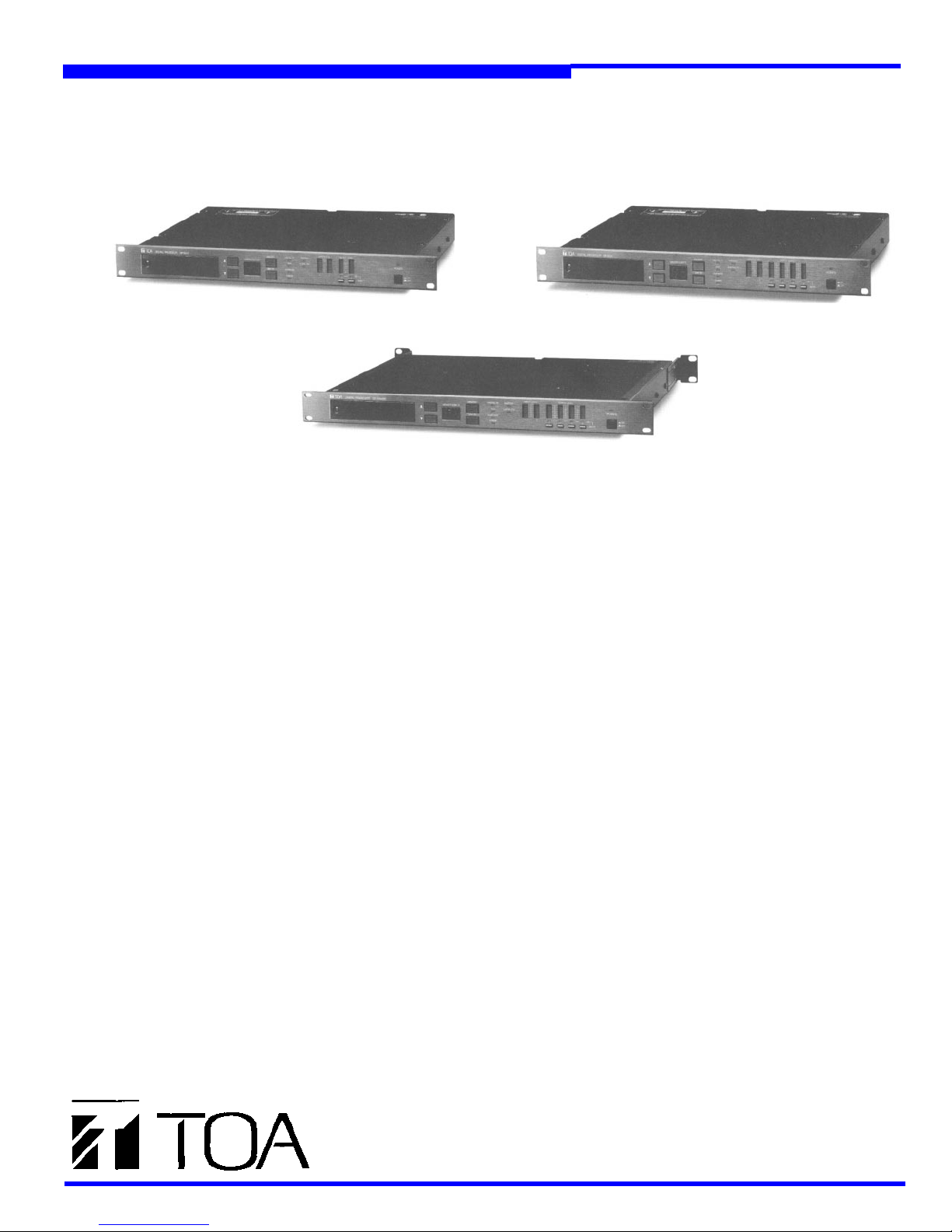
TOA’s New DP-0204SR Touring Sound DSP
DP-0202 Digital Signal Processor (2 in/2 out)
DP-0204 Digital Signal Processor (2 in/4 out)
DP-0204SR Touring Sound Digital Signal Processor (2 in/4 out)
DESCRIPTION
The DACsys
DSP processors that provide more than 20 different types of
all-digital signal processing functions for audio system signals between the mixer output and the power amplifiers.
They are designed to provide highly flexible configurations
to meet a wide variety of applications including performing
art centers, houses of worship, sports facilities, theaters
and, now, touring sound applications with the DP-0204SR.
Incorporating a wide range of sophisticated parameter control for the various processing functions, TOA’s DSPs set
the standard for digital processing in both quality and quantity of tools available to the user. For example, you can have
up to 68 full parametric EQ filters simultaneously on-line in
one DP-0204. Each unit, or a system comprised of up to 30
devices, is controlled using an intuitive, user friendly graph-
ic PC interface. This software allows easy access and
changes to any of the processing functions and configura-
tions to meet almost almost any system requirement. In
addition, it provides off-line editing and data file storage of
system set-up. The signal flow and parameter settings can
also be easily stored in and recalled from each device’s 16
non-volatile memories. The hardware is space efficient and
is designed to prevent unauthorized changes to the pro-
cessing via multiple levels of security. By using units either
singly or linked in multiples, systems of almost any size or
configuration can easily be designed, set-up, and installed.
II
DP-0202, DP-0204, and DP-0204SR are
FEATURES
◆ Electronically balanced analog and AES/EBU digital
inputs and outputs.
◆ Easy set-up of signal flow and processing functions.
◆ Individualized selection of signal flow and processing as
needed for unique requirements.
◆ Signal processing and configuration set via software.
◆ 16 on-board memories store and recall presets.
◆ Remote control of memory presets by PC or logic
switching via multi-pin connection on rear panel.
◆
One rack-space unit (1-3/4”).
UNIQUE FEATURES OF DP-0204SR
◆ Gold-plated internal connectors will not oxidize or
corrode.
◆
Ruggedized chassis for touring.
◆
Rear rack-mounting ears for touring.
DACsys
DP-0202
DP-0204
DP-0204SR
DX-0808
PC Control Software (Included with each product)
II
SERIES PRODUCTS
Digital Signal Processor (2 in/2 out)
Digital Signal Processor Unit (2 in/4 out)
Touring Sound Digital Signal
Processor (2 in/4 out)
8 x 8 Digitally controlled routing and level
control matrix
Page 2

PROGRAMMABLE INPUT/OUTPUT
CONFIGURATIONS
◆
DP-0202: 1 in/2 out
1 in/1 out + 1 in/1 out
◆
DP-0204:
1 in/4 out
1 in/3 out + 1 in/1 out
1 in/2 out + 1 in/2 out
◆
DP-0204SR: 1 in/4 out
1 in/3 out + 1 in/1 out
1 in/2 out + 1 in/2 out
PROGRAMMABLE SIGNAL PROCESSING
FUNCTIONS
◆ 1/3 Octave or 2/3 Octave Graphic Equalizers, or
16-band full-function parametric equalizers
◆ 3, 4, and 7-Band multi-function filter sets with the
following functions:
Full function parametric filtering
Low and High-Pass Filtering
Low and High-Frequency Shelving
All-Pass Filtering
High Frequency Horn Boost EQ
Notch Filtering
◆
Signal Delay
◆ Full Function Compressor/Limiter
◆
Attenuation
◆
Gain
◆
Output Muting
◆
Symmetric and Asymmetric Crossover Filters
◆
Noise
Gate
◆
Polarity lnverter
OTHER FUNCTIONS
◆ Graphic displays of Frequency and Phase Response
◆ System Lock and Password Protection
◆ Input and Output analog Gain and Padding
◆
Muting of all Outputs
◆ Storage of 16 Presets in Memories with Numeric
Indicator
◆ Input Level Meters
◆
Output Level Meters
◆ PC Communication using RS-485 or RS-232C
APPEARANCE AND DIMENSIONAL DIAGRAMS
DP-0202
DP-0204
TYPICAL PC SOFTWARE SCREENS
16 Band Parametric
Equalizer
1/3 Octave Graphic
Equalizer
Crossover Filter
Compressor/Limiter/
Noise Gate
Configure Unit
DP-0202
Unit: in. (mm)
UNIT:Mm
SCALE: 1/4
Page 3

SIGNAL FLOW EXAMPLES
DP-0202
EQ Mode 1in 1out x 2
DP-0204
EQ Mode
1in 2out x 2
X-over Mode
1in 2out x 2
Signal Processing Modules
1in 3out + 1
EQ Mode 1in 2out
1in 3out + 1 1in 4out
X-over Modules
X-over Mode 1in 2out
1 in 4out
EXAMPLES OF AVAILABLE FUNCTIONS
DP-0202
EQ Mode 1in 1out x 2
X-over Mode 1 in 2out
DP-0204
EQ Mode 1in 2out x 2
X-over Mode 1in 2out x 2
X-over Mode 1in 3out + 1
DACsys
II
SERIES PC CONTROL SOFTWARE
FEATURES
◆ Single software program controls all DACsys II products
◆ Sets configurations and all parameters of up to 30 units
in real time
◆ Configurations and memory presets can be designed
off-line in the office for later downloading
◆
User-friendly graphic displays
◆ Easy access to each processing function with graphic,
simultaneous display of all parameter settings
◆ Display of frequency/phase response for each filter set
and each output channel for DSP processors
◆ Unlimited storage of signal-flow configurations and sig-
nal processing parameter settings of each device in
data files on hard or floppy disks for archiving and
downloading to the hardware units
ARCHITECT’S AND ENGINEER’S
SPECIFICATIONS
The unit shall be an all-digital signal processing system providing comprehensive post-mixer signal processing for sound reinforcement, production systems and touring sound applications. The
unit shall have 2 inputs and 4 [2] outputs for analog or digital audio
signals. There shall be 16 non-volatile memory presets for storage
and recall of different processing parameter settings. The unit shall
incorporate all solid state circuitry.
Nominal analog input sensitivity shall be: +4dBu (maximum
+23dBu), 10k ohm input impedance, electronically balanced.
Maximum gain shall be 18dB (6dB analog plus 12dB digital). Hum
and noise shall be at least 105dB IHF-A below maximum output.
Frequency response shall be +0/-1dB (ref 1kHz) from 20Hz to
20kHz. Analog power outputs shall be nominal +4dBu (maximum
+24dBu) into a 600 ohm load, electronically balanced with less than
0.05% THD at 1 kHz. Analog to digital and digital to analog conversions shall be done with full 20-bit resolution.
The inputs shall be switchable to accept either analog or
digital audio signals. The outputs, independently of the inputs, shall
be switchable to emit either analog or digital audio signals. Digital
inputs and outputs shall be provided with a TTL level sensitivity and
75 ohm input impedance.
The signal processing functions shall be inscribed in
replaceable firmware (EPROM) within the unit. This will allow
upgrades to and changes in the unit’s signal processing functions.
Digital processing functions shall include: gain; attenuation; polarity
inversion; parametric and graphic equalization; signal delay; compression; limiting; noise gate; low and high frequency shelving boost
filters; low and high frequency shelving cut filters; crossover filter
slope and type; all-pass filtering; notch filtering; and uniform directivity horn EQ. Parameters and parameter ranges for processing functions typically shall be quantitatively variable in ways beyond what is
normally available for similar analog functions.
All signal flow and processing functions shall be externally
configured, programmed and controlled through the RS-232C or RS486 ports. The RS-485 ports shall provide the means to link up to 30
units together with control by one external computer. With the external computer control disconnected, the memory preset selection can
be made globally for all units by changing the preset on the designated master unit. The RS-232C port shall allow external control of a
single unit. Units may be subsequently linked using the RS-485 ports
for global memory changes and full control of all units.
Computer software for use with a PC shall be provided to
configure, program and control the units. The software shall be a
graphical Windows-based program that allows downloading and
uploading of configuration and parameter settings and has the capability to store settings as binary files. The program shall provide
graphical representations of the configuration showing the signal flow
and signal processing functions; dialog boxes showing all parameter
setting for each processing function; listing of units in the system; and
listings of memory presets. a graphical plot of both frequency and
phase response shall be provided for individual equalizer processing
functions, and for input-to-output for each output channel. The soft-
ware shall provide functional lock-outs under hardware switch set-
tings and password protection to prevent unauthorized changes.
The AC line mains shall be 50/60Hz, 100V-240V and power
consumption shall be 36W. The digital signal processor shall be
enclosed in a durable, painted, black, 0.04 in steel enclosure
mechanically reinforced by a 0.08 in. thick, black anodized, aluminum front panel. Overall dimensions shall be 19” w x 1.74” h x
12.9” d. Weight shall be 11 Ibs. Standard E.I.A. rack-mount hole
spacing shall be included. The digital Signal Processor shall be the
TOA model DP-0204 [DP-0204SR, DP-0202].
Page 4

SPECIFICATIONS**
Model Number DP-0202, DP-0204, DP-0204SR
Performance
Frequency Response
Total Harmonic Distortion
Crosstalk
Propagation Delay
Input and Output
Analog Input
Analog Output
Electrically
Digital Input/Output
A/D Converter
D/A Converter
Dynamic Range
Sampling Frequency
Number of Inputs and Outputs
Signal Processing
Gain/Attenuation
Compressor/Noise Gate
Compressor Threshold
Compressor Ratio
Attack/Release Time
Noise Gate Threshold
Parametric Equalizer
Number of Bands
Center Frequency
Gain
Q
1/3 Octave Graphic Equalizer
Number of Bands
Center Frequency
Boost/Cut
Q
High Pass Filter
Low Pass Filter
Horn Equalization
2/3 Octave Graphic Equalizer
Number of Bands
Center Frequency
Boost/Cut
Q
High Pass Filter
Low Pass Filter
Horn Equalization
3, 4 and 7 Band Filter
Low Pass Filter
High Pass Filter
All Pass Filter
High Boost Filter
High Attenuation Filter
Low Boost Filter
Low Attenuation Filter
Notch Filter
Parametric Filter
Horn Equalization
Signal Delay
Delay Time
Reference Unit
Delay Steps
Crossover Network
Type/Slope
Crossover Frequency
Delay Time
Gain/Attenuation
DP-0202
DP-0204
DP-0204SR
20Hz to 20kHz, +0dB, -1.0dB
Less than 0.05% at 1 kHz, +4dBu*
Less than -8odBu* at 1 kHz
2.37msec. plus equivalent analog filtering delay
+4dBu*(Maximum +23dBu*), I0k ohms,
Electrically balanced, XLR-3-31 type connector
+4dBu*(Maximum +24dBu*), 600 ohms,
balanced, XLR-3-32 type connector
AES/EBU format, XLR-3-31/3-32 type connector
20 bit
20 bit
at least 105dB (IHF-A Weighted)
48kHz
2-in/2-out
2-in/4-out
2-in/4-out
+12.0dB to -60.0dB (-
0.5dB steps with polarity inverter
24dBu* to -16dBu*, 1 dB steps
1:1, 2:1, 3:1, 4:1, 8:1, 12:1, 20:1, ∞
0.02msec to 100msec/10 to 5000msec
-72dBu* (16 points
20 Hz to 20kHz continuously variable type
+150dB to -15.0dB, 0.5dB step
0.267 to 34.620, 8 step selectable
31(Maximum 16 bands used simultaneously)
20 Hz to 20kHz, ISO standard
+15dB/-15dB
3.5, 5.0, 7.0 (Selectable)
20Hz to 18kHz, -12dB/Oct.
20Hz to 18kHz, -12dB/Oct.
0dB to + 18dB at 20kHz, 1dB step, +6dB/Oct.
16
20 Hz to 20kHz, ISO standard
+ 15dB/-15dB
3.5, 5.0, 7.0 (Selectable)
20Hz to 18kHz, 12dB/Oct.
20Hz to 18kHz, 12dB/Oct.
0dB to +18dB at 20kHz, 1dB step, +6dB/Oct.
20Hz to 20kHz, Q=0.5 or 0.7
20Hz to 20kHz, Q=0.5 or 0.7
20Hz to 20kHz, Q=0.267 to 34.620
(8 Steps Selectable)
Shelving type, 6.0kHz to 20kHz
0dB to +12dB (0.5dB Step)
Shelving type, 20kHz to 500kHz
0dBu* to -12dBu* (0.5dB Step)
Shelving type, 20kHz to 500kHz
0dB to +12dB (0.5dB Step)
Shelving type, 20kHz to 500kHz
0dB to -12dB (0.5dB Step)
20Hz to 20kHz, Q=8.65 to 69.25
(4 steps selectable)
Full-function Parametric Filter
0dB to +18dB at 20kHz, 1db step filter
+6dB/Oct.
0 to 1.365sec
Millisecond, meter, inch, feet (Selectable)
2lµsec (Fine), 5.333msec (Coarse) switchable
2-way (DP-0202)
2-way, 3-way, 4-way (DP-0202/DP-0204SR)
Bessel, 12dB/Oct., 18dB/Oct., 24dB/Oct.
Butterworth, 12dB/Oct., 18dB/Oct.,24dB/Oct.
Linkwitz-Riley, 12dB/Oct., 24dB/Oct.
20Hz to 10kHz, symmetric and asymmetric,
1/12 Oct. steps
0 to 682msec, 21µsec step
+12.0dB to -60.0dB (-∞ dB)
0.5dB steps with polarity inversion
∞
∞
dB)
dB) to-26dBu*, 1dB steps
Mute
Others
Parametric Link Up to 256 groups
Parameter Comparison
Other Functions
Memories
Analog Input Gain
Analog Output Padding
Security
Hardware
Software
Control
Communication Ports Connectors
Programming Software System Requirement
Hardware
:1
Software
Memory Input/Output
Connector
Function
Word Clock External Input
Panel Functions (Front Panel)
Input Selector
Output Selector
Word Clock Selector
Memory Selection
ID Number Setting
Display
Operating Status LEDs
Level Meters
Headroom Indication
Input
output
Mute Switches
Power Switches
Panel Functions (Rear Panel)
Ground Lift Switch
Power Inlet
Power Requirement
Power Consumption
Physical
Dimensions
Color
Weight
Accessories
*0dBu=0.775V RMS
**Specifications are subject to change without notice
Individual output mute, All output mute
Between edited and memory preset parameters
16 Hardware Memory Presets
0, +6dB (Switchable)
0, -6dB, -12dB (Switchable)
3 status switch settings;
Password protected; configuration lock only,
configuration and parameter edit lock
RS-485, RS-232C (On/Off)
XLR-3-31 type, RS-485 input
XLR-3-32 type, RS-485 output
Two DB9 female RS-232C (Front and rear panel)
PC compatible
80386 or higher,
Math Co-processor recommended for the
frequency and phase response graphic display
4MB of memory or higher
1MB HDD space
VGA Color Monitor recommended
Mouse Recommended
Windows 3.1 or later
8 pin, mini DIN
Logic level memory control input and memory
status output
TTL level, 75 ohms, BNC connector
Analog inputs/digital inputs, switchable
Analog outputs/digital outputs, switchable
Internal/external, switchable
Up/down keys
Momentary slide switch and up/down keys
2-digits, 7-segment LED display, memory
number and unit number, switchable
up/down key selection
DIGITAL IN (green), RUN (green), EMPHASIS
(green), ERROR (red), MASTER (green),
OVERFLOW (red)
7 LEDs bar graph meter, 0dB (red)
6/18/24/30/42/60dB (green)
2 Channels
2 Channels(DP-0202)
4 channels (DP-0204, DP-0204SR)
Each output w/LED (green)
Power ON/OFF w/LED (green)
Normal/lift
3 pin, IEC-320 standard
AC100V to AC240V, 50/60Hz
36 watts maximum
19”w x 1.75”h x 12.9”d, EIA 1 rack unit size
Black, anodized aluminum (Front Panel), black
painted steel (Chassis)
11 Ibs.
(1) AC power Cord
(1) Tamper Proof Screw for front security cover
(Replaces a standard Phillips head screw)
(2) Instruction Manuals (l-hardware, l-software)
(1) Software Diskette (2HD, 3.5”)
Off: All function available
1; Lock all but memory
2; Lock all functions
Printed in U.S.A. 9/97 bofors
 Loading...