

Page 1

OPERATING INSTRUCTIONS
INTERFACE UNIT
DI-1616
TABLE OF CONTENTS
1. SAFETY PRECAUTIONS
……………………………………………………
2
2. GENERAL DESCRIPTION
………………………………………………
3
3. FEATURES
………………………………………………………………………………………………
3
4. HANDLING PRECAUTIONS
…………………………………………
3
5. NOTES ON PERSONAL COMPUTER
SOFTWARE
…………………………………………………………………………………………
3
6. PART NAMES AND FUNCTIONS
Front Panel
………………………………………………………………………………………………
4
Rear Panel
………………………………………………………………………………………………
5
7. PERSONAL COMPUTER CONNECTIONS
7.1 When using the RS-232C
…………………………………………
6
7.1 When using the RS-485
………………………………………………
7
8. UNIT NUMBER AND COMMUNICATIONS
PORT SETTINGS
…………………………………………………………………………
8
9. BACKUP BATTERY REPLACEMENT
…………
8
10. APPEARANCE
………………………………………………………………………………
9
11. SPECIFICATIONS
………………………………………………………………
10
Please follow the instructions in this manual to obtain the optimum results from this unit.
We also recommend that you keep this manual handy for future reference.
Page 2
2
1. SAFETY PRECAUTIONS
●
Be sure to read the instructions in this section carefully before use.
●
Make sure to observe the instructions in this manual as the conventions of safety symbols and messages
regarded as very important precautions are included.
●
We also recommend you keep this instruction manual handy for future reference.
Safety Symbol and Message Conventions
Safety symbols and messages described below are used in this manual to prevent bodily injury and property
damage which could result from mishandling. Before operating your product, read this manual first so you are
thoroughly aware of the potential safety hazards as well as understand the safety symbols and messages.
■■
When Installing the Unit
●
Do not expose the unit to rain or an environment
where it may be splashed by water or other liquids,
as doing so may result in fire or electric shock.
●
Use the unit only with the voltage specified on the
unit. Using a voltage higher than that which is
specified may result in fire or electric shock.
●
Do not cut, kink, otherwise damage nor modify the
power supply cord. In addition, avoid using the
power cord in close proximity to heaters, and
never place heavy objects -- including the unit
itself -- on the power cord, as doing so may result
in fire or electric shock.
■■
When the Unit is in Use
●
If you detect smoke or a strange smell coming from
the unit during use, immediately switch off the
power and disconnect the power supply plug from
the AC outlet. Then, contact your nearest TOA
dealer. Make no further attempt to operate the unit
in this condition as this may cause fire or electric
shock.
●
To prevent a fire or electric shock, never open nor
remove the unit case as there are high voltage
components inside the unit. Refer all servicing to
your nearest TOA dealer.
●
Do not place cups, bowls, or other containers of
liquid or metallic objects on top of the unit. If they
accidentally spill into the unit, this may cause a fire
or electric shock.
■■
When Installing the Unit
●
Never plug in nor remove the power supply plug
with wet hands, as doing so may cause electric
shock.
●
When unplugging the power supply cord, be sure
to grasp the power supply plug; never pull on the
cord itself. Operating the unit with a damaged
power supply cord may cause a fire or electric
shock.
●
Avoid installing the unit in humid or dusty locations,
in locations exposed to the direct sunlight, near the
heaters, or in locations generating sooty smoke or
steam as doing otherwise may result in fire or
electric shock.
■■
When the Unit is in Use
●
Switch off the power, and unplug the power supply
plug from the AC outlet for safety purposes when
cleaning or leaving the unit unused for 10 days or
more. A fire or electric shock may result.
WARNING
Indicates a potentially hazardous situation which, if mishandled,
could result in death or serious personal injury.
Indicates a potentially hazardous situation which, if mishandled,
could result in moderate or minor personal injury, and/or property
damage.
WARNING
CAUTION
CAUTION
Page 3

2. GENERAL DESCRIPTION
The DI-1616 is a dedicated interface unit for the power amplifiers P-1030D, P-1060D, P-1090D, IP-300D,
IP-450D and IP-600D. The power amplifiers' operating conditions and signal levels can be monitored and
adjusted at the personal computer.
The P-1030D, P-1060D and P-1090D require an interface module which is optionally available.
3. FEATURES
●
Operating status can be monitored and signal levels adjusted for up to 16 channels (8 power amplifiers) per
unit.
●
Different memory patterns can be stored in 16 built-in memories. By calling up one of the memory patterns
through control from a personal computer or from the DP-0202, DP-0204 (both digital processors) or DX0808 matrix unit, signal levels can be changed for each connected amplifier.
●
The unit, DP-0202, DP-0204, and DX-0808 can be connected and controlled as an integrated system
through the RS-485 control line.
●
Wide operating voltage range of 90-250 VAC.
4. HANDLING PRECAUTIONS
●
Either an optional dedicated module IF-101S or IF-101X is required when using the P-1030D, P-1060D or
P-1090D.
●
To monitor and control the power amplifiers at the computer, dedicated software is required. For the
software, contact your nearest TOA dealer.
●
Switch on the power after completing all connector connections.
●
Avoid installing the unit directly above the power amplifier in the equipment rack, in locations where the unit
is exposed to the sunlight, or in humid or dusty locations because the unit may fail.
●
The DI-1616 is a precision equipment. Do not give a shock or vibration to it.
5. NOTES ON PERSONAL COMPUTER SOFTWARE
Computer software for the unit is common to the control software for the DP-0202, DP-0204, and DX-0808.
However, be sure to use the software of Version 2.0 or greater (usable on Windows 95/98 and Windows
NT4.0).
3
Page 4
4
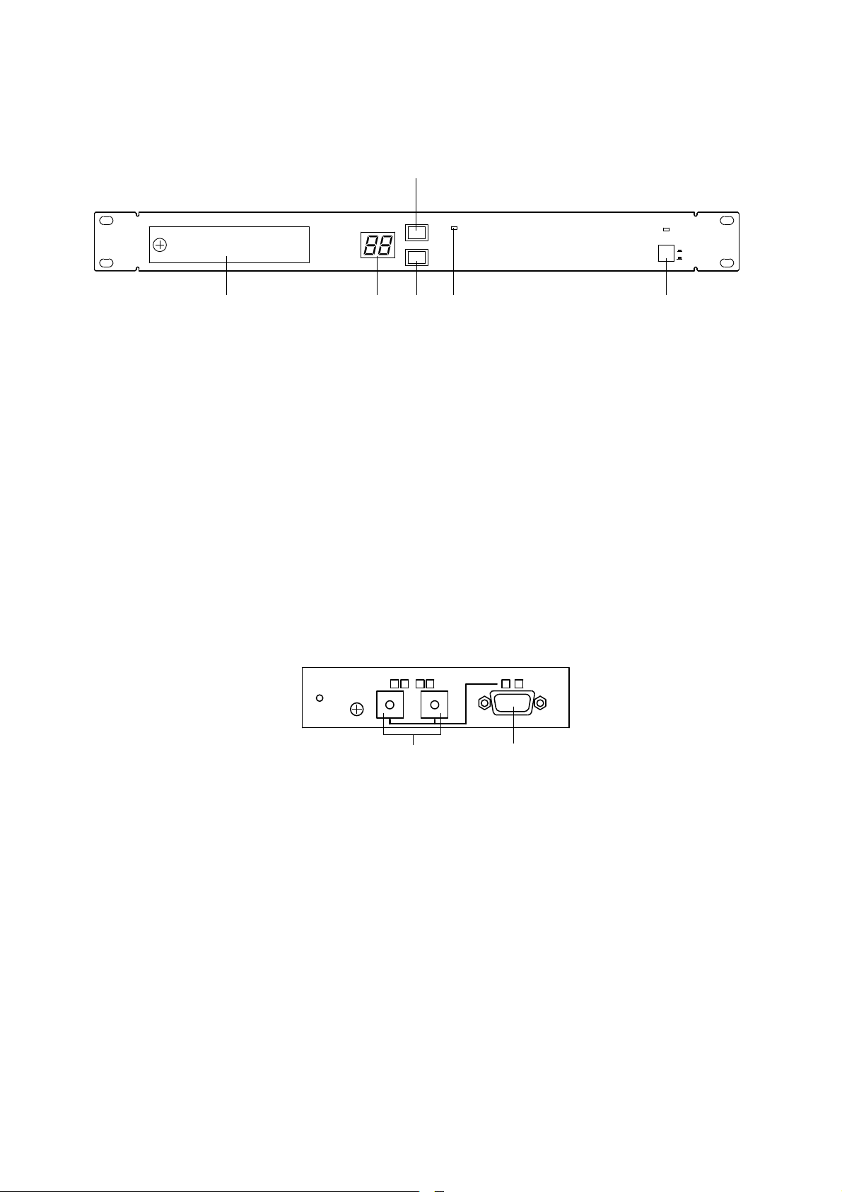
6. PART NAMES AND FUNCTIONS
① Power switch [ON/OFF]
If the power is switched on, the power indicator
lights and the unit is set for the mode it was last in
before the power was switched off.
② Master unit indicator [MASTER]
Lights to indicate a master unit (set for unit No.
1). For the unit number setting, refer to p. 8 "8.
UNIT NUMBER AND COMMUNICATIONS PORT
SETTINGS".
③ Memory key [MEMORY]
Pressing this key will show a memory number
being currently called up on the display
④ Unit number key [UNIT ID]
If this key is pressed, the unit number of the unit
flashes on the display.
⑤ Display [MEMORY/UNIT ID]
Displays either a memory number or a unit
number.
⑥ Compartment cover
For details of its inside, refer to the section [Front
Compartment].
MEMORY/UNIT ID
MASTER
UNIT ID
MEMORY
POWER
ON
OFF
①②
③
④⑤⑥
00 0013
〜
RS-485
PORT/UNITIDSET
RS-232C
⑧
⑦
[Front Compartment]
[ Front Panel ]
⑦ Unit number/port setting DIP switch [PORT/UNIT ID SET]
Two DIP switches are provided to set unit numbers. The RS-232 communications port located in the
compartment can be used when the two switches are set for [0][0], and the rear-mounted RS-485
communications port (XLR connector) when the switches are set for a number other than [0][0]. For the unit
number and DIP switch settings, refer to p. 8 "8. UNIT NUMBER AND COMMUNICATIONS PORT
SETTINGS".
⑧ Master unit indicator [MASTER]
This port employs a 9-pin D-sub connector for the RS-232C communications and is used when connecting
a personal computer directly. This port can be used only when DIP switches ⑦ are set for [0][0]. For its
connection, refer to p. 6 "7. PERSONAL COMPUTER CONNECTIONS".
Page 5

5
[Rear Panel]
100/240 V 50/60 Hz
GND
LIFT
NORM
RS-485
CH2 CH1
AMP 8
CH2 CH1
AMP 7
CH2 CH1
AMP 6
CH2 CH1
AMP 5
CH2 CH1
AMP 4
CH2 CH1
AMP 3
CH2 CH1
AMP 2
CH2 CH1
AMP 1
⑫
⑪ ⑩ ⑨
⑨ Interface connectors [AMP1 CH1,CH2-AMP8 CH1,CH2]
Connect to the CONTROL I/O connector located on the rear panel of each power amplifier or on the
interface module. These interface connectors are of 8-pin DIN type, and optional cables (CX-9CC-2: 2 m or
CS-9CC-5: 5 m) are made available.
⑩ RS-485 communications port [RS-485]
This port employs a 3-pin XLR connector for RS-485 communications, and can be used when DIP switches
located in the front compartment are set for other than [0][0]. Use this port to connect equipment when
using two or more DI-1616 units or when interlocking the DI-1616 with the DP-0202, DP-0204 or DX-0808.
Refer to p. 6 "7. PERSONAL COMPUTER CONNECTIONS" for connection, and to p. 8 "8. UNIT NUMBER
AND COMMUNICATIONS PORT SETTINGS" for DIP switch setting.
⑪ Ground lifting switch [GND]
Cuts a noise-generating ground loop created when the DI-1616 is connected with other equipment in an
equipment rack. Usually, set this switch to the NORM position.
⑫ AC inlet
Connects to the supplied AC power cord.
Page 6

6
Power amplifier (1)
Power amplifier (8)
RS-232C control
CX-9CC-2 or CX-9CC-5
:9-pinD-subconnector
(option)
00 0013
〜
[Front]
[Rear]
DI-1616
[Fig.1]
7. PERSONAL COMPUTER CONNECTIONS
The DI-1616 interfaces the power amplifier with the personal computer, and lets the computer display the
power amplifier status or set the signal level on the computer's screen. Up to 30 DI-1616s (240 power
amplifiers) can be controlled. Although the digital processors DP-0202 and DP-0204, and the matrix unit DX0808 can be controlled simultaneously, the total number of all connected units must be up to 30 per system.
Both RS-232C and RS-485 interface standards can be used. The communication speed is 192,000 bps.
●
RS-232C
Use this port when the system includes only one DI-1616 unit and the distance between the unit and
personal computer is shorter than 10 m.
●
RS-485
Use this port when using only one DI-1616 and the distance to the computer exceeds 10 m or when using
plural DI-1616s or when using the DI-1616 in combination with the DP-0202, DP-0204, and/or DX-0808.
7.1 When using the RS-232C
Because only one unit is connected, the unit number is 1. Set DIP switches in the front compartment for [0][0],
and connect the unit to the personal computer as shown in Fig. 1. Use a straight cable for the communications
cable.
Connect the computer's RS-232C connector to the unit's RS-232C connector (9-pin D-sub connector) located
in the front compartment.
Note
The RS-232C is a one-to-one communications method. However, as a guideline, the maximum transmission
distance is 10 m. If exceeding 10 m, it is recommended that the RS-485 port be used even though only one
unit is connected.
Page 7

7
CX-9CC-2 or CX-9CC-5
RS-232C/485
Converter
Up to 30 units in total
RS-485
control
RS-232C
contorol
Power amplifier (1)
Power amplifier (8)
Power amplifier (1)
Power amplifier (8)
:XLR-3-31 type(op
:XLR-3-32 type(op
DP-0204
DP-0202
DX-0808
DI-1616
DI-1616
UNIT ID No.1
UNIT ID No.2
UNIT ID No.3
UNIT ID No.4
UNIT ID No.5
[Fig.2]
7.2 When using the RS-485
Because multiple units are controlled, a unit number must be preset for each unit. To preselect the DI-1616 as
unit No. 1, set DIP switches in the front compartment for [0][1]. Refer to p. 8 "8. UNIT NUMBER AND
COMMUNICATIONS PORT SETTINGS" for DIP switch setting.
Figure 2 shows the example of connection between the personal computer and each unit. Note that an
adaptor to convert the RS-232C port into RS-485 type is required because personal computers are usually
equipped with only the RS-232C port. Connect the personal computer's RS-232C port to the female RS-485
connector on the rear panel of equipment of unit No. 1 via the conversion adaptor. Connect other units as
shown in Fig. 2. Up to 30 units can be connected.
Notes
●
When the system employs the DI-1616 together with the DP-0202, DP-0204, or DX-0808, do not select the
DI-1616 as unit No. 1.
●
Both DP-0202 and DP-0204 incorporate a RS-232C/RS-485 converter function. Therefore, when the DP0202 or DP-0204 is designated as master unit, it can be directly connected to the personal computer
without using the conversion adaptor. In this case, make the same connection as for the RS-232C control
(see Fig.1).
Page 8

8
8. UNIT NUMBER AND COMMUNICATIONS PORT SETTINGS
When using two or more DI-1616s or when using the DI-1616 together with the DP-0202, DP-0204 (both
digital processors) and/or DX-0808 (matrix unit), different numbers must be given to different equipments so
that the personal computer transmits data to each connected equipment. This number is a unit number,
which must be preset in consecutive numbers of 1-30.
●
Unit number setting
1. Open the front compartment using a screwdriver.
2. Switch on the power.
3. Press the unit number display key [UNIT ID] on the front panel.
4. Using two DIP switches in the compartment, set a unit number.
●
Example
Set the switches for [0][1] if a unit number is 1, and for [2][5] if No. 25. The set number flashes on the display.
●
Notes on equipment of unit No. 1
The DIP switches on equipment of unit No. 1 can be set for [0][0] (RS-232C port) or [0][1] (RS-485 port) to
allow selection of the communications port. Referring to p. 6 "7. PERSONAL COMPUTER CONNECTIONS",
select either port. In either case, a number [1] flashes on the display.
●
Starting values
The unit is factory-preset to unit No. 1 ([0][0], RS-232C port). Take care not to assign the same unit number to
different units. To confirm the unit's unit number, press the unit number display key on the front panel.
9. BACKUP BATTERY REPLACEMENT
The DI-1616 has an internal battery for data backup. Note the following points when replacing the battery.
●
Type of battery
One CR-2032 lithium battery is used. Be sure to use the same type battery when replacing.
●
Life of battery
Approximately six years. It is highly recommended that the battery be replaced at shorter intervals.
●
Low voltage indication
If the battery voltage drops below the marginal level, the indication of "39" is shown on the memory/unit ID
display on the front panel. Replace the battery immediately when this indication is displayed.
●
How to replace
Follow the procedures below to replace the battery without erasing data stored in the unit.
1. Supply the power to the unit continuously for over ten minutes.
2. After supplying the power, set the power switch to the OFF position and remove the AC cord from a wall
outlet.
3. Open the unit's top panel.
4. Pull out the battery from the circuit board, and quickly replace it with a new one. Data can be maintained if
the battery is replaced within five minutes.
Note: Take care correct polarities (face and back of the battery) when installing a new battery.
Page 9

9
10. APPEARANCE
Unit: mm
4-6x10
483
465
31.8
44
286.2
280
Page 10

AC100 – 240 V, 50/60 Hz, 15 W
20 – 20 kHz (+0 dB, –2 dB)
Under 0.07% (1 kHz, +4 dB*)
16 channels (8 power amplifiers)
8-pin Mini-DIN connector
Input: 16 channels, +4 dB*, 10 kΩ, unbalanced
Output: 16 channels, +4 dB*, 2 kΩ, unbalanced
Level setting: 0 to – ∞ dB changeable in 1 dB steps (muting: – ∞ dB)
Power supply status, protection, fan (temperature), output level
16 memory patterns
Single unit control: RS-232C, 9-pin D-sub connector
Plural units control: RS-485, XLR-3-31 and XLR-3-32
Double-digit LED
Green LED
Operating on the Windows 95/98 and Windows NT4.0
Front panel: Rolled steel plate, black, paint
Case: Surface-treated steel plate, black
482 (w) x 44 (h) x 294 (d) mm
4 kg
10
11. SPECIFICATIONS
* 0 dB = 0.775 V
Notes
• The design and specifications are subject to change without notice for improvement.
• Windows and Windows NT are trademarks of Microsoft Corporation.
• Accessories
AC power cord ........................................... 1
Rack mounting screw ................................. 4
Instruction manual ...................................... 1
Power Source
Frequency Characteristics
Distortion
Control/Monitoring
Level Control
Monitoring
Memory
Interface Standard
Memory/Unit No. Display
Master Display
PC Software
Finish
Dimensions
Weight
Page 11

Page 12

133-12-507-20
 Loading...