

Toa DI-100, DI-110 Installation Manual

INSTALLATION MANUAL
DI-100
DIRECT SELECT INTERFACE DI-110
Please follow the instructins in this manual to obtain the optimum results from these units.
We also recommend that you keep this manual handy for future reference.
TOA Electronics, Inc.
1

WARNING : (For USA only)
This equipment generates, uses, and can radiate radio frequency energy, and if not installed and used
in accordance with the instructions manual, may cause interference to radio communications. It has
been tested and found to comply with the limits for a Class A computing device pursuant to Subject J
of Part 15 of FCC Rules, which are designed to provide reasonable protection from such interference
when operated in a commercial environment.
Operation of this equipment in a residential area is likely to cause interference, in which case the
user, at his own expense, will be required to take whatever measures may be required to correct the
interference.
CONTENTS
1. INSTALLATION PRECAUTIONS................................................................................................................................................................... 2
2. GENERAL DESCRIPTION............................................................................................................................................................................... 3
3. SYSTEM CONFIGURATION ...........................................................................................................................................................................3
4. PRINCIPLE OF OPERATION AND BLOCK DIAGRAM............................................................................................................................4
4.1 Principle of Operation
4.2 Block Diagram
5. SYSTEM DESIGNING PROCEDURE............................................................................................................................................................. 4
6. INSTALLATION
6.1 DIÐ100Õs Address Setting ...................................................................................................................................................................... 5
6.2 DIÐ110Õs Address Setting and Card Connection............................................................................................................................5 ~ 6
6.3 Wiring the LEDÕs....................................................................................................................................................................................7
6.4 Control Panel Switch Wiring...........................................................................................................................................................7 ~ 8
6.5 Wiring of Relay Outputs ........................................................................................................................................................................ 8
6.6 Wiring to the ASÐ110 .............................................................................................................................................................................8
6.7 Wiring to the ASÐ100A........................................................................................................................................................................... 9
6.8 Wiring to the LU Cards.......................................................................................................................................................................... 9
6.9 Power Supply Connection ..................................................................................................................................................................... 9
7. PERFORMANCE TESTING
7.1 Test Program Initiation .......................................................................................................................................................................... 9
7.2 Testing Contents .................................................................................................................................................................................. 10
8. PROGRAMMING
8.1 Equipment Connection......................................................................................................................................................................... 10
8.2 Programming with the IBM Personal Computer ...............................................................................................................................11
8.3 ASÐ100A/ASÐ110 Programming......................................................................................................................................................... 11
9. OPERATION
9.1 Calling................................................................................................................................................................................................... 12
9.2 Being Called (When in Continuous Call Tone Mode) ....................................................................................................................... 12
9.3 To Terminate the Conversation .......................................................................................................................................................... 12
9.4 Other Functions.................................................................................................................................................................................... 12
10. PROGRAMMING SHEET.......................................................................................................................................................................13 ~ 18
11. SPECIFICATIONS ........................................................................................................................................................................................... 19
1. INSTALLATION PRECAUTIONS
• Use a regulated power supply (24V DC, +/- 4 volts) to ensure correct operation without overload.
• Wire only the rated switches to the switch terminals, or damage could result.
• Wire only LEDÕs to the LED terminals, or damage could result.
• Do not exceed voltage rating to the relays, or severe damage could result.
2
2. GENERAL DESCRIPTION
The DIÐ100 and DIÐ110 interface boards are designed to be used in conjunction with the ICÐ100 Institutional
Communication System and ASÐ100A/ASÐ110 Control Stations. This will allow a control station operator to make or
receive calls from other stations with the push of (1) switch on custom or off-the-shelf control panels. Calls to or from
corresponding sub-stations can be announciated by flashing LEDÕs on the control panel or numerically in the associated
ASÐ100A or ASÐ110.
3. SYSTEM CONFIGURATION
IC-100
MU-110
LU-100
LU-200
2 x Twisted
pair cable
POWER
SUPPLY
(24V DC)
DI-100
DI-110
DI-110
DI-110
DIRECT SELECT
CONTROL STATION
2 x Twisted pair cable
+ 3 conductors
AS-100A
AS-110
SWITCH
&
LED
(Fig. 1)
3
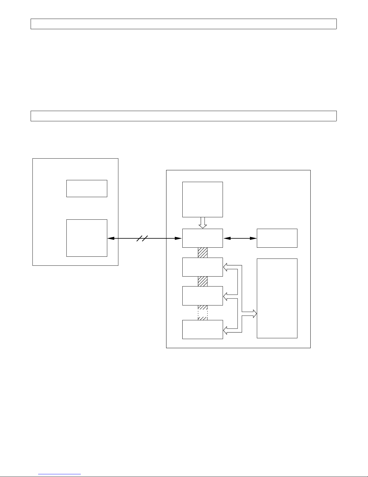
4. PRINCIPLE OF OPERATION AND BLOCK DIAGRAM
4.1 Principle of Operation
The DIÐ100 outputs dial pulse to the ASÐ100A/AsÐ110 according to control data transmitting from the MUÐ110. The DIÐ
100 also transmits a flashing or steady LED signal, relay control signal, etc. to the DIÐ110, and can periodically scan the
control panel switches.
4.2 Block Diagram
CPU
(Z80)
DI-100
ROM EEPROM RAM MODEM TO MU-110
OUTPUT
PORT
CALL-IN
LED
BUSY
LED
CCTV
RELAY
DI-110
CONTROL
INPUT
PORT
DRIVER
DRIVER
DRIVER
STATION
CONTROL
CONTROL
LATCH
LATCH
LATCH
TO AS-100A/
AS-110
DI-110
5. SYSTEM DESIGNING PROCEDURE
(1) Determine number of ports needed in the system. (LED indications, relay outputs, etc.)
(2) Determine number of the DIÐ110 cards needed.
(3) Calculate power requirements and select a power supply.
(4) Select LEDÕs and switches to be used.
(5) Fill out the programming sheet. (See pages 13~18.)
4
INPUT
PORT
(Fig. 2)
6. INSTALLATION
S
WARNING : TURN OFF ALL POWER TO THE SYSTEM BEFORE UNPLUGGING OR PLUGGING
IN CONNECTORS TO THE CARDS. THESE CARDS CONTAIN CMOS ICÕS AND MAY BE
DAMAGED BY STATIC DISCHARGE. IT IS ADVISABLE TO WEAR AN EARTH GROUNDED
WRIST STRAP WHEN HANDLING THE CARDS.
6.1 DIÐ100Õs Address Setting
Set SW1 corresponding to the LU card number connected to the DIÐ100, referring to Fig. 3 and Table 1.
DIÐ100
SW1
(Fig. 3)
LU Card No.
1
OFF
SW 1
1 2 3 4
2
OFF
1 2 3 4
3
OFF
1 2 3 4
4
OFF
1 2 3 4
(SW1 is factory-preset to the LU card's No. 1.)
6.2 DIÐ110Õs Address Setting and Card Connection
(1) DIÐ110Õs Address Setting
Set SW1 and SW2 corresponding to the DIÐ110 card number, referring to Fig. 4 and Table 2.
LU Card No.
5
6
7
8
SW 1
OFF
1 2 3 4
OFF
1 2 3 4
OFF
1 2 3 4
OFF
1 2 3 4
(Table 1)
DIÐ110
W 2
SW 1
(Fig. 4)
5
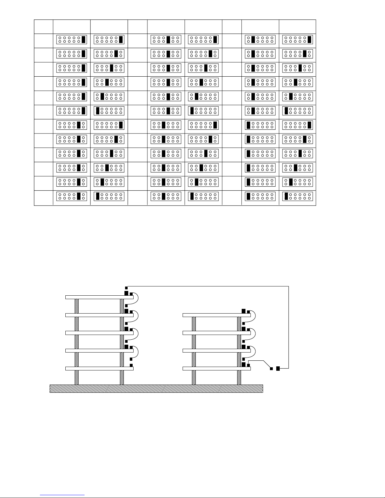
DI-110
No.
1
2
3
4
5
6
7
8
9
10
11
12
SW 1 SW 2
61
61
61
61
61
61
61
61
61
61
61
61
61
61
61
61
61
61
61
61
61
61
61
61
DI-110
No.
13
14
15
16
17
18
19
20
21
22
23
24
SW 1 SW 2
61
61
61
61
61
61
61
61
61
61
61
61
61
61
61
61
61
61
61
61
61
61
61
61
DI-110
No.
25
26
27
28
29
30
31
32
33
34
35
36
SW 1 SW 2
61
61
61
61
61
61
61
61
61
61
61
61
61
61
61
61
61
61
61
61
61
61
61
61
(SW1 and SW2 are factory-preset to the DI-110 No. 1.)
(Table 2)
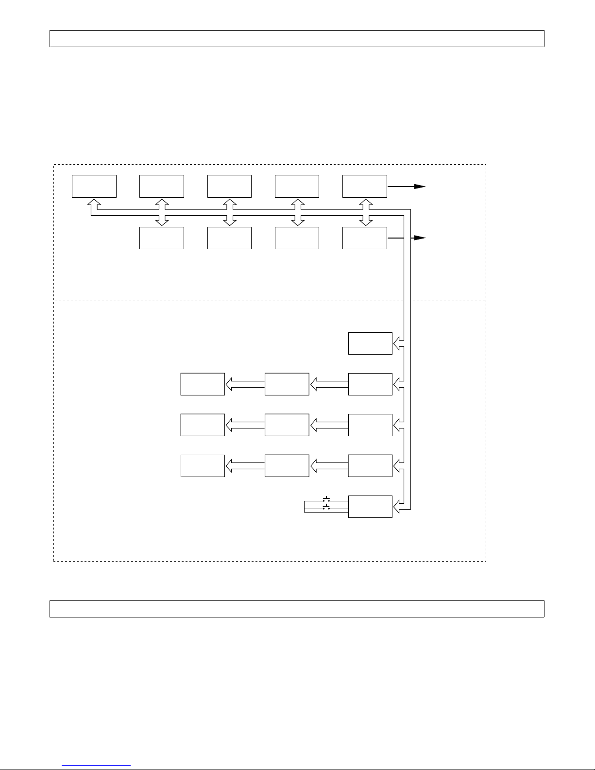
(2) DIÐ100/DIÐ110 Card Rack Installation
Install the DIÐ100/DIÐ110Õs inside the control panel shown in Fig. 5 with stand-offs or use the CKÐ100 and install at
the equipment rack. Connect the cards with the ribbon cables as shown below.
DI-110 (4)
DI-110 (3)
DI-110 (2)
DI-110 (1)
DI-100
DI-110 (8)
DI-110 (7)
DI-110 (6)
DI-110 (5)
6
(Fig. 5)
(Fig. 9)
 Loading...