

Page 1

SOFTWARE INSTRUCTION MANUAL
DIGITAL PROCESSOR DP-0206
Please follow the instructions in this manual to obtain the optimum results from this unit.
We also recommend that you keep this manual handy for future reference.
DACsys2000
Version 2.00
Page 2

TABLE OF CONTENTS
1. Before installation ................................................................................... 3
2. Installation method ................................................................................... 4
3. Launching the application ................................................................................... 8
4. Main window ................................................................................... 9
5. Outline of the menu functions ................................................................................... 10
6. Unit operation ................................................................................... 13
7. Unit Viewer ................................................................................... 18
8. Memory Viewer ................................................................................... 20
9. Flow Viewer ................................................................................... 21
10. Contents Viewer ................................................................................... 23
11. Response Viewer ................................................................................... 38
12. Preset Memory ................................................................................... 41
13. Level Monitor Viewer ................................................................................... 42
14. Mute All Window ................................................................................... 43
15. Communications ................................................................................... 44
16. User Level ................................................................................... 46
17. Prohibition Settings ................................................................................... 48
18. Print ................................................................................... 50
19. Export ................................................................................... 51
20. DQ-C01 Settings ................................................................................... 52
21. Supplement ................................................................................... 60
22. Specifications ................................................................................... 62
2
Page 3

1. Before installation
DACsys 2000 is software created to allow you to change settings for the DP-0206.
This setting software can be used in the following environments: Microsoft Windows
95/Windows 98/Windows ME/Windows NT Ver. 4.0/Windows 2000.
The format for the floppy disk is 1.44 megabytes (MS-DOS format for IBM compatibles).
Make sure your machine is an IBM compatible capable of formatting 3.5-inch floppy disks at
1.44 megabytes (MS-DOS format). This software will not operate on a machine that operates
under a different format.
3
Page 4
2. Installation method
There are two installation disks (labeled Disk 1 of 2 and Disk 2 of 2).
Proceed with installation as follows:
Be sure to close any applications that are running before beginning the installation process.
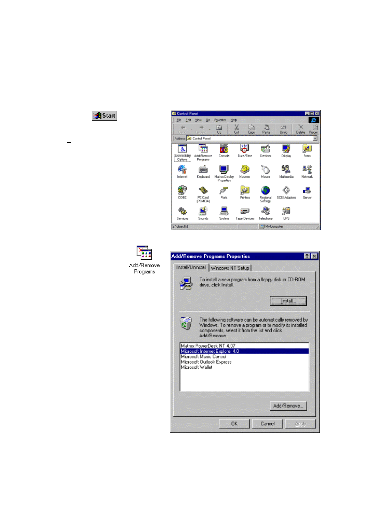
1. Click the
screen and select Settings
Control Panel. The window shown
at right will appear.
2. Double-click the icon
in the Control Panel window to
display the window shown at right.
button on the
→
4
Page 5

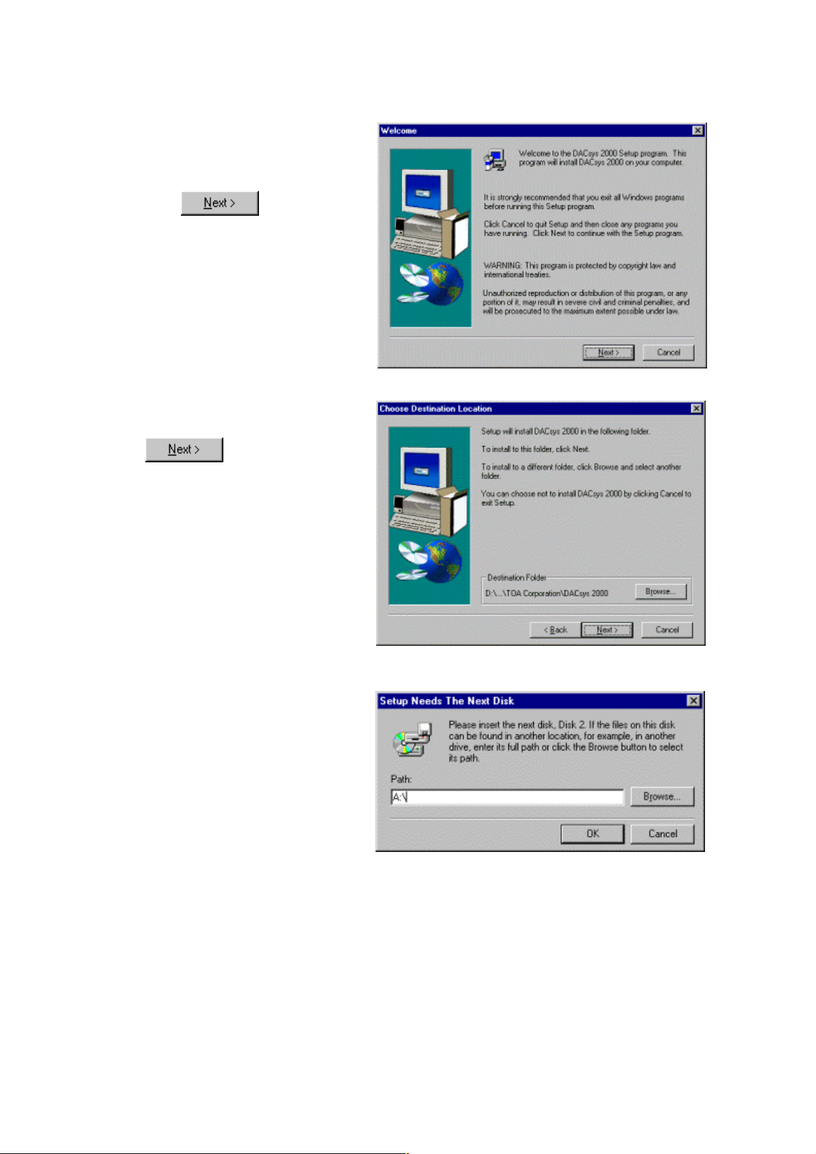
3. Click . The window
shown at right will appear.
4. At this point, insert the system disk (Disk 1 of 2) in the floppy-disk drive and click
.
5. The system will search the setup
program, and the window shown at
right will appear. Then click
.
6. During the preparation for
installation, the window shown at
right will be displayed.
5
Page 6
7. If the window shown at right
appears, carefully read the
information in the window and then
click
.
8. Carefully read the information in
the window and then click
.
9. If the window shown at right
appears, remove the disk (Disk 1
of 2) from the drive and insert Disk
2 (Disk 2 of 2), then click “OK”.
6
Page 7

10. If the message indicating
completion of setup appears, click
.
7
Page 8
3. Launching the application
To launch the application once it has been installed, follow either of the two procedures
described below:
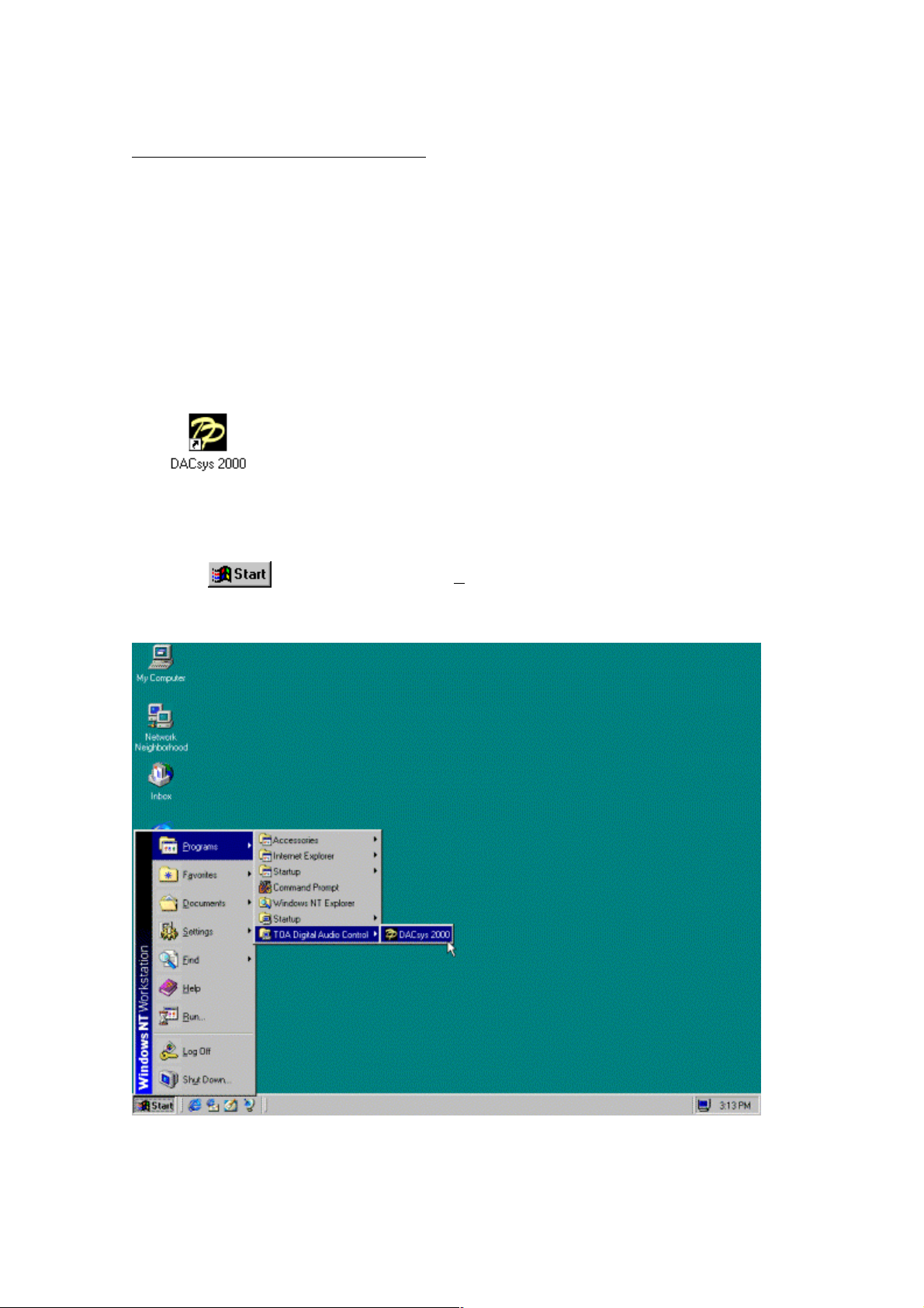
1. Create a desktop shortcut and launch the application by clicking its icon.
Drag the icon DACsys 2000 (which will be displayed immediately when installation is
completed) with the mouse while holding the Ctrl key pressed and drop it onto the desktop (to
copy the icon). This will set it up as a shortcut on your desktop. Then launch the application
by double-clicking this shortcut icon.
2. Proceed in steps from the Windows Start button.
Click
on the screen the select Program → TOA Digital Audio Control → DACsys2000
to launch the application.
8
Page 9
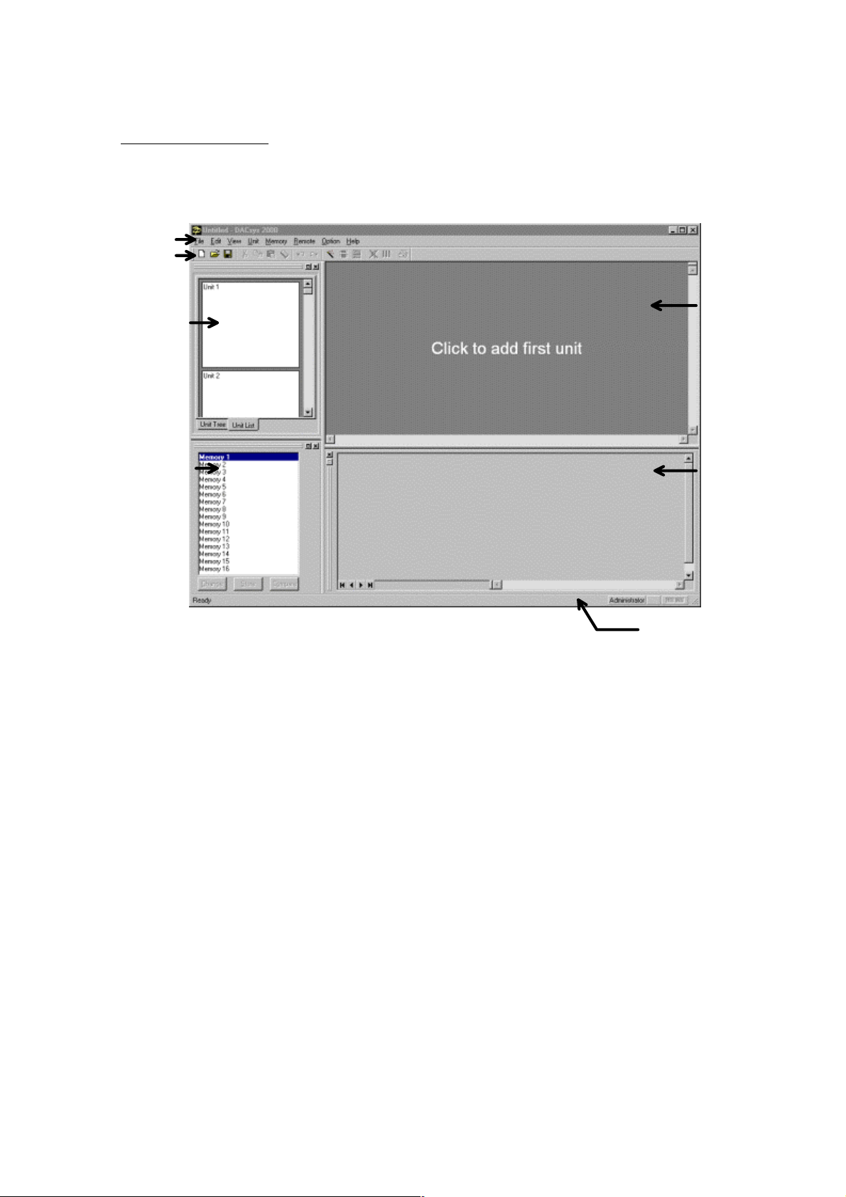
4. Main window
The window shown below will appear when the application is launched.
Menu Bar
Toolbar
Unit Viewer
Flow Viewer
Memory Viewer
Contents Viewer
Status Bar
9
Page 10

5. Outline of the menu functions
File
New... : Creates (sets) a new data file
Open... : Opens an already existing data file
Save : Saves the data file in use on a disk
Save As... : Saves the data file in use on a disk under a different name
Export... : Exports the data of the active document as the Microsoft
Excel data. The menu regarding the export appears only
when the Microsoft Excel is installed in the PC.
Page Settings... : Changes the print margin.
Print... : Prints the active document
Print Preview... : Displays full pages
Exit : Closes the application
Edit
Undo : Undoes the last action
Redo : Redoes the previously undone action
Cut : Saves the setting value in the box in which the cursor is
located on the clipboard and restores the initial value
Copy : Copies the setting value in the box in which the cursor is
located on the clipboard
Paste : Pastes the data on the clipboard into the box in which the
cursor is located
Clear : Restores the setting value in the box in which the cursor is
located to the default value
Swap Gain < - > C/G : Makes the Gain and C/G boxes trade positions
Filter Type
è PEQ : Changes the box in which the cursor is located to a PEQ box
(with the default setting for PEQ)
è GEQ : Changes the box in which the cursor is located to a GEQ box
(with the default setting for GEQ)
è Filter : Changes the box in which the cursor is located to a Filter box
Split
è PEQ+Filter : Filter is divided into PEQ and Filter
è GEQ+Filter : Filter is divided into GEQ and Filter
è Filter+Filter : Filter is divided into Filter and Filter
Merge : Unites with one Filter
10
Page 11

Set Grouping... : Creates a box group
Release Grouping : Releases the boxes of the current group and cancels the
group
Write Protect to Box
è Low : The operator is prohibited from changing of the parameter of
Box
è Mid : The operator is prohibited from changing of Box all
è High : The change of the parameter in Box by Administrator is
prohibited, and the operator is prohibited from changing all.
View
Toolbar : Shows/hides the toolbar
Status Bar : Shows/hides the Status Bar
Unit View : Shows/hides the Unit Viewer
Contents View : Shows/hides the Contents Viewer
Response View : Shows/hides the Response Viewer(p. 38)
Memory View
è Show/Hide : Shows/hides the Memory Viewer
è Floating : Floats the Memory Viewer
è Docking : Docks the Memory Viewer
Mute All
è Show/Hide : Shows/hides the Mute All Window(p. 43)
è Floating : Floats the Mute All Window
è Docking : Docks the Mute All Window
Level Monitor View : Shows/hides the Level Monitor Viewer
Unit
Create New Unit... : Creates a new unit
Delete Unit : Deletes the unit from the data file
Change Unit Configuration... : Changes the number of inputs and outputs of existing units
Change X-over
è Combination... : Changes the combination of the crossover
è Slope... : Changes the slope of the crossover
Names... : Changes the names of the unit and the inputs and outputs
Save as a Unit Template
è Unit Template... : Saves the unit settings in a file as a template
è X-over Template... : Saves the crossover settings in a file as a template
11
Page 12

Memory
Change
è Memory1 - 16 : Recalls a preset from one of the 16 preset -memory cells
Store
è Memory1 - 16 : Stores the status in one of the 16 preset -memory cells
Names... : Changes the name of a memory cell
Remote
Connect... : Connects the PC with the unit to set online status
Disconnect : Breaks the connection between the PC and the unit for off-
line status (any changes in settings made at the PC when
off-line will not affect the unit's settings)
Bulk transmission... : The data of the file which is opening now is compelling
transmitted
Bulk receiving... : All the data of the unit is received
Auto Connection... : Next time, when the file is opened, connects it automatically
Option
Security Settings... : Setting the user level and the prohibition setting of various
operations are done.
External Control... : Makes the setting of the external control
Help
About : Displays the version of DACsys 2000
12
Page 13
6. Unit operation
Creating a unit
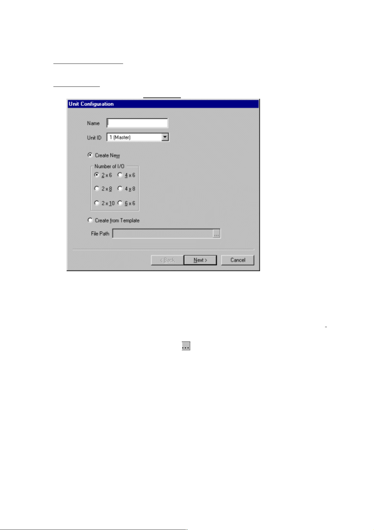
1. Select from the menu bar Unit → New... to open the Unit Configuration window.
2. In the Unit Configuration window, first input the name of the unit then select a unit ID.
3. Select the number of inputs and outputs from among 2 x 6, 2 x 8, 2 x 10, 4 x 6, 4 x 8, and 6 x
6. The initial value is 2 x 6. When using an already existing template file, select "Create from
Template". You can directly input a filename, or you can make a selection from the dialog box,
which can be displayed by clicking the
part.
13
Page 14
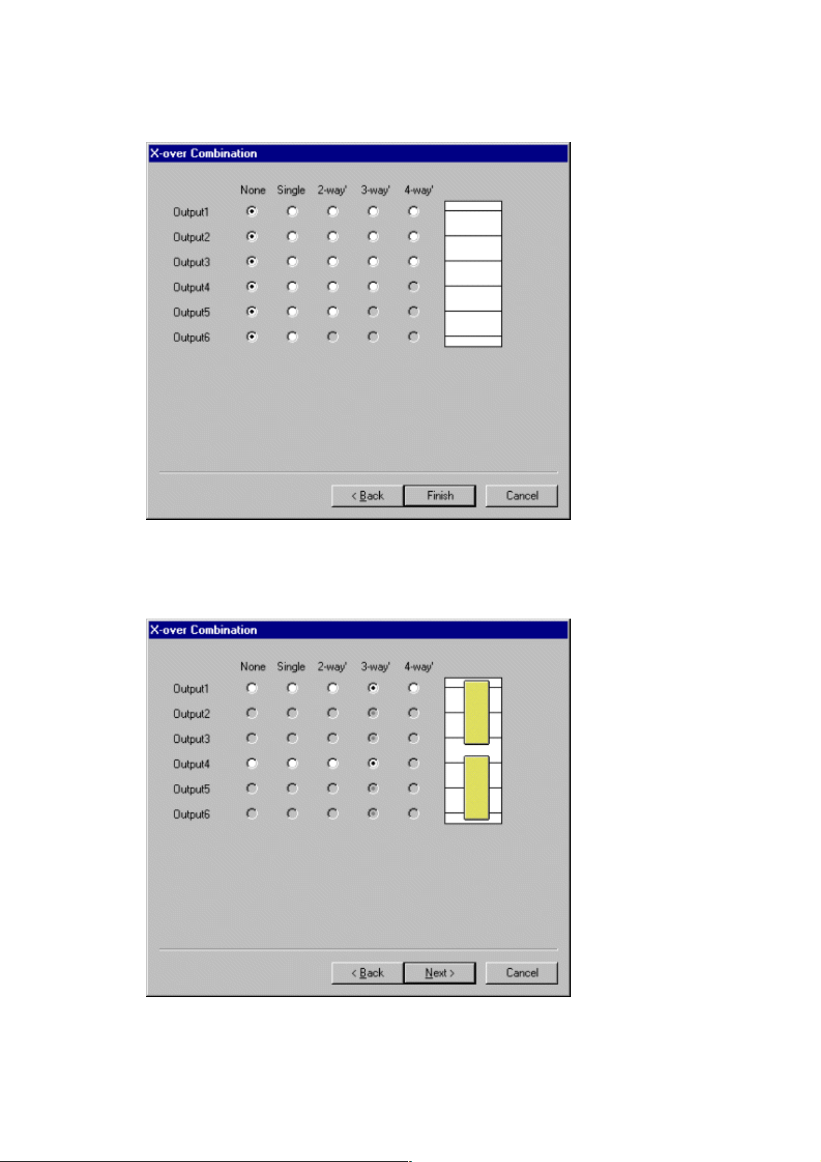
4. Click “Next”. The X-over Combination window will appear.
5. Make the crossover combination settings by first clicking the appropriate spaces. The setting
status is displayed in the right-hand portion of the window. Below is an example of a 3-
way/2-channel setup when 6 outputs are in use.
14
Page 15
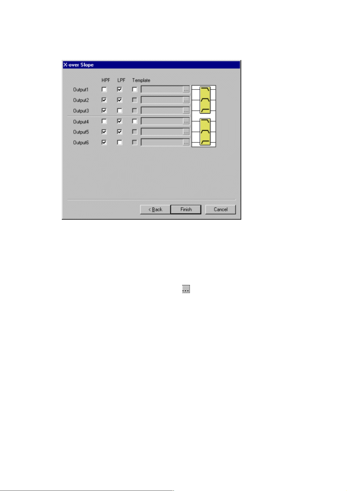
6. Click “Next”. The X-over Slope window will then appear.
7. Make the X-over slope settings by clicking the appropriate check boxes. The settings status
for each output is displayed in the right-hand portion of the window.
8. When using an existing template file, click the check box for the corresponding channel's
“Template”. You can directly input a filename, or you can make a selection from the dialog
box, which can be displayed by clicking the
part.
15
Page 16
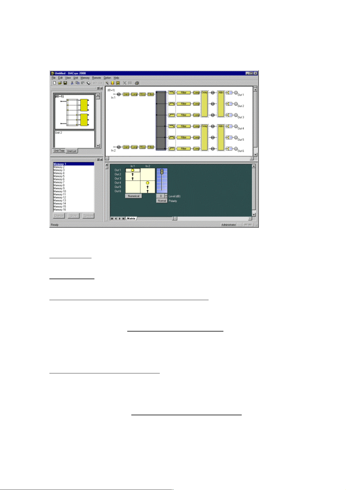
9. Check the correctness of your settings and click “Finish”. The Signal Flow area will appear,
as shown in the figure below.
Deleting a unit
Select the unit you wish to delete in the Unit Viewer or Flow Viewer. From the menu bar, select
→ Delete... to display a confirmation dialog box. Click “OK” to delete the selected unit.
Unit
Changing the number of inputs and outputs of the unit
You can change the number of inputs and outputs of an already created unit. Select the unit
whose input/output number you want to change in the Unit Viewer or Flow Viewer.
From the menu bar, select Unit
→ Change Unit Configuration... to display the Unit Configuration
window.
Then make the settings just as you would when creating a unit.
Changing the Crossover Combination
You can change the crossover combination of an already created unit.
Select the unit whose crossover combination you want to change in the Unit Viewer or from the
Flow Viewer.
From the menu bar, select Unit
→ Change X-over → Combination... to display the Crossover
Combination window. Then make the settings as in the creation procedure.
16
Page 17

Changing the Crossover Slope
You can change the crossover slope of an already created unit. Select the unit whose crossover
slope you want to change in the Unit Viewer or Flow Viewer.
From the menu bar, select Unit
→ Change X-over → Slope... to display the Crossover Slope
window. Then make the settings as in the creation procedure.
Changing the name of the unit
Select the unit whose name you want to change in the Unit Viewer or Flow Viewer.
From the menu bar, select Unit
→ Names... to display the Change Name dialog box.
Saving a unit as a template
Select the unit you want to save as a template in the Unit Viewer or Flow Viewer.
From the menu bar, select Unit
→ Save as a Unit Template → Unit Template... to display the Save
File dialog box.
Saving the Crossover settings as a template
Select the Crossover box you want to save as a template in the Flow Viewer.
From the menu bar, select Unit
→ Save as a Unit Template → X-over Template... to display the
Save File dialog box.
17
Page 18
7. Unit Viewer
This section explains about the Unit Viewer.
The units are displayed in one column. It is possible to display up to 30 units.
There are two display modes. You can switch between them by clicking the tab at the bottom.
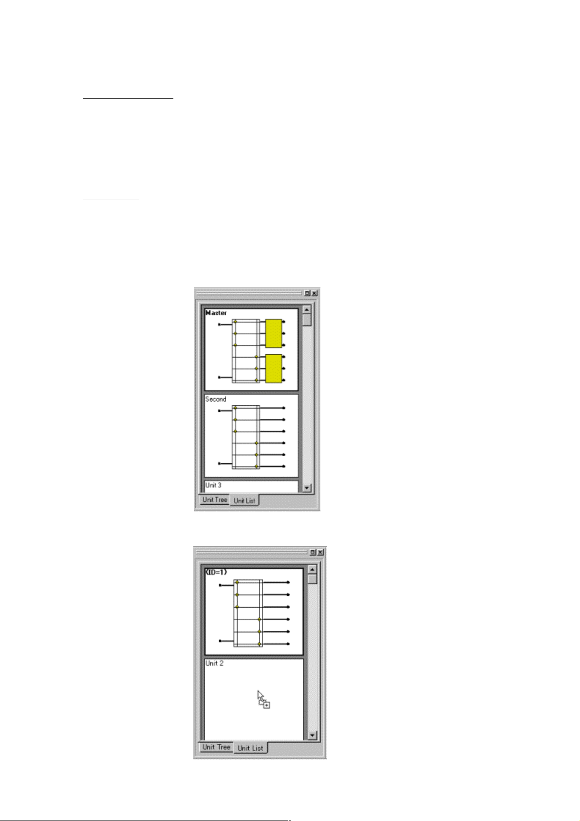
List display
It is possible to reduce size of the signal-processing image of the units and display up to 30 units.
The unit name, the number of inputs and outputs, the matrix settings, and the crossover
combination information will be displayed abbreviated. By clicking an already created unit, you
can scroll through a linked Flow Viewer.
In the list display, the unit can be copied onto an empty unit by the created unit drag & drop.
18
Page 19
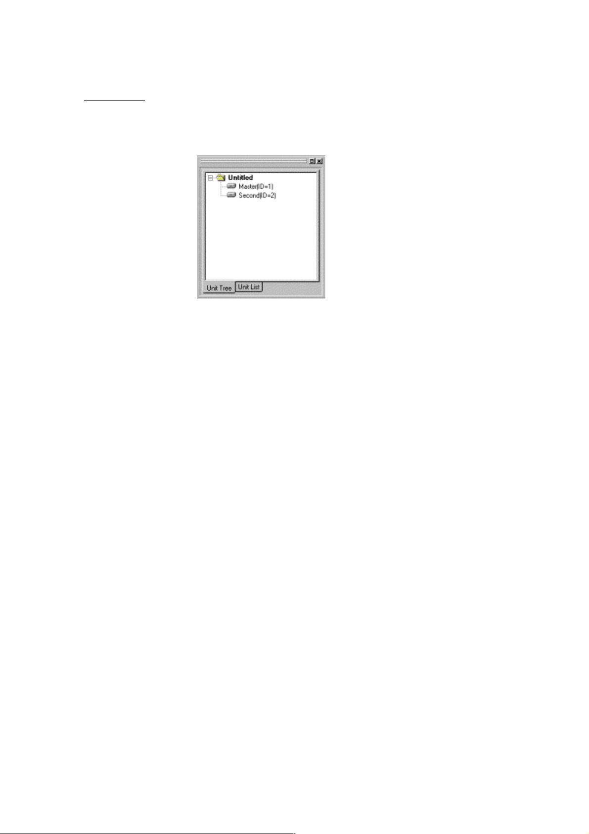
Tree display
You can display up to 30 units in a comparatively small display area. The unit names will be
displayed in a tree format. By clicking an already created unit, you can scroll through a linked
Flow Viewer.
19
Page 20
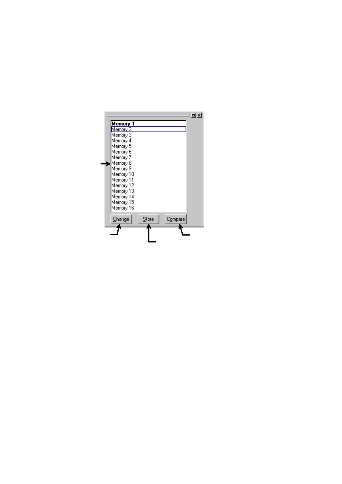
8. Memory Viewer
This section explains about the Memory Viewer.
The name and numbers of selected memory cells are displayed. By recalling a memory cell you
can make additions to that cell or compare the content of memory cells.
Memory list
Change button
Store button
Compare button
- The memory cell number selected in the Memory list box is highlighted in bold letters.
- To recall a memory cell, click the desired memory cell number then click “Change”.
- To write to a memory cell, click the number of the memory cell in which you wish to store the
information then click “Store”.
- To perform memory comparison, click the number of the memory cell to compare and click
“Compare”. The display will then be switched temporarily to the selected preset memory number.
To compare the content of a memory with that before edit, click the number of the memory cell
highlighted in bold letters and click “Compare”. The previous status will be restored when you
once again click “Compare”.
- The Memory area can be switched between docked and floating indications.
20
Page 21
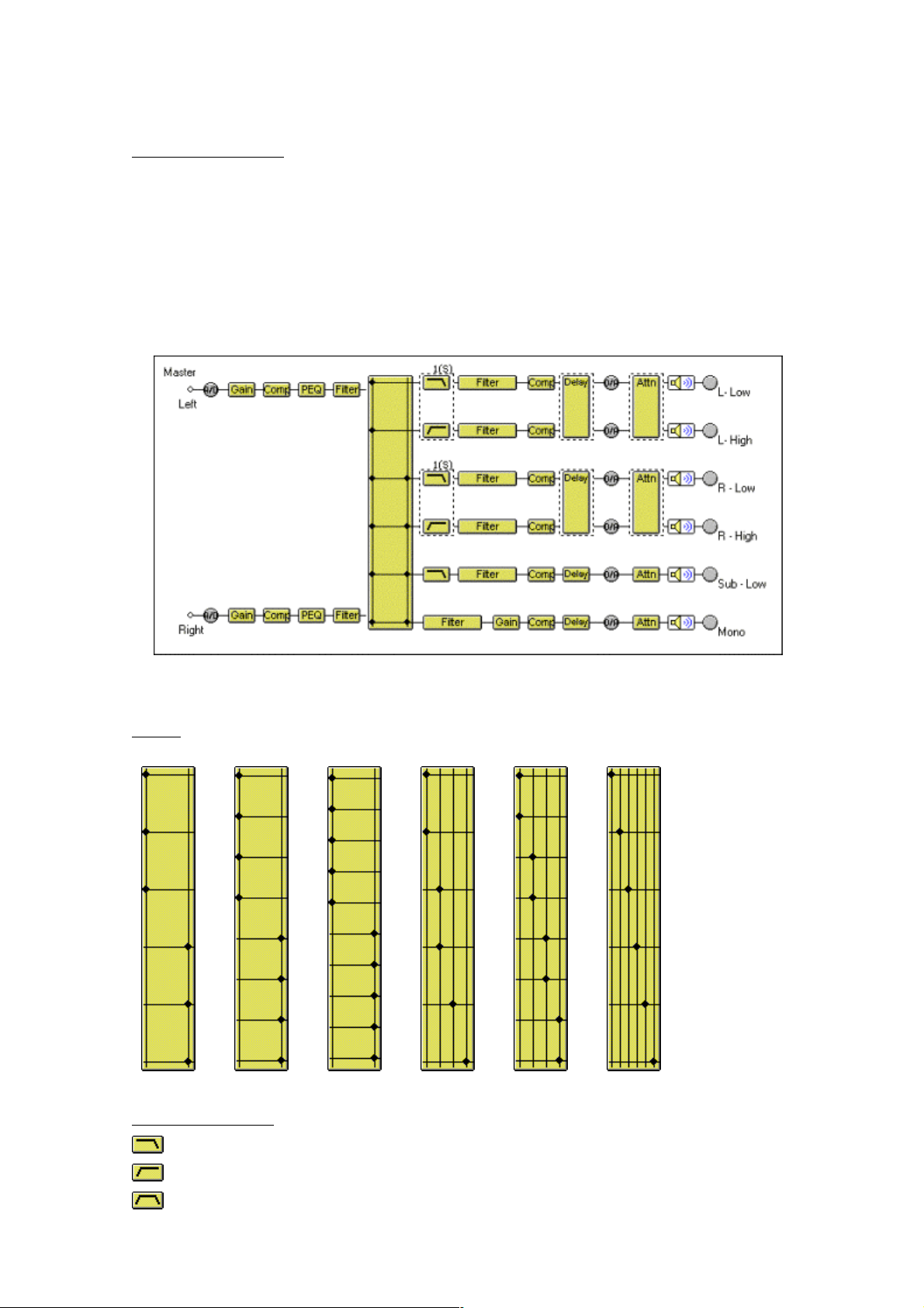
9. Flow Viewer
This section explains about the Flow Viewer.
In the Flow Viewer a box is displayed to indicate the signal-processing functions of the unit and a
graphical representation of the unit's signal-processing flow, showing each signal flow as a
straight line connecting input and output.
The figure below is one example of the unit with a 2-input/6-output configuration.
The signal-processing functions of each box are presented below.
Matrix
2 in 6 out 2 in 8 out 2 in 10 out 4 in 6 out 4 in 8 out 6 in 6 out
Crossover (Xover)
← Low-Pass Filter
← High-Pass Filter
← Band-Pass Filter(Low-Pass Filter + High-Pass Filter)
21
Page 22

Other boxes
← Gain
← Compressor/Noise gate
← Parametric equalizer
← Graphic equalizer
← Filters
← Delay
← Attenuater
← Mute (off)
← Mute (on)
Mute settings
To mute a channel, double-click the output's box. A “X”(cross) will appear in the box, and
that channel will be muted.
→
.
→ To cancel muting, double-click again on the same box.
Signal indicator
← Displays the signal level immediately after A/D conversion.
← Displays the signal level immediately after D/A conversion.
← Displays the output level.
Red : The signal level is above 18 dB*
Green : The signal level is above -48 dB* but under 18 dB*
Gray : The signal level is under -48 dB*
* 0dB = 0.775V
22
Page 23

10. Contents Viewer
This section explains about each Contents Viewer.
To display the Contents Viewer, click the desired box of the Flow Viewer.
Matrix
Matrix control
Fader
Level-setting button
Polarity inversion button
Value-display-switching button
- The symbols in the matrix-control boxes indicate the input/output routing.
- Double-clicking a matrix-control box toggles the display between on/off.
- The bold line framing a matrix-control box indicates the selected matrix point.
- By moving the fader switch up or down, you can change the level of the selected matrix point.
- The level for the selected matrix point is indicated as a numerical value on the level-setting
button. Clicking this button enables you to directly input a numerical value. The spin button on the
right allows you to increase or decrease the level in increments of 1 dB.
- The polarity-inversion button displays the polarity status of the selected matrix point. Click this
button to invert the polarity.
- Click the value-display-switching button to display the level setting of each matrix point.
23
Page 24

Gain
Grouping button
Fader
Gain-display button
Polarity-inversion button
Mute button
- By moving the fader switches up or down, you can change the level for each channel.
- The grouping number set for each channel is displayed on the grouping button. Clicking this
button enables you to set the grouping for each channel. When moving the fader switch up or
down for grouped channels, the switch of each fader belonging to the same group moves in the
same way.
- The level for each channel is indicated as a numerical value on the level-display button. Clicking
the button enables you to directly input a numerical value. Using the spin button on the right, you
can move the numerical values up or down in increments of 0.5 dB.
- The Polarity-inversion button displays the polarity setting for each channel. By clicking this
button you can invert the polarity.
- The Mute button displays the on/off status of the mute function for each channel. By clicking this
button you can switch this function on/off.
24
Page 25

Comp/Gate
Compressor Ratio handle
Compressor Threshold handle(red)
Display-switching tab
Gate Threshold handle(blue)
Compressor Reduction meter
Gate-status indicator
- By dragging the Compressor Threshold handle diagonally, you can change the compressor
threshold level.
- By dragging the Compressor Ratio handle up or down, you can change the compressor ratio.
- By dragging the Gate Threshold handle diagonally, you can change the noise-gate threshold
level.
- The effectiveness of the compressor is displayed with a yellow graph bar on the Compressor
Reduction meter.
While the Noise Gate is working, the Gate-status indicator lights blue.
- If you click the All tab, the setting window for all the channels of the unit is displayed.
Compressor Threshold button
Compressor Ratio button
Compressor Sync button
Compressor Attack button
Compressor Release button
Gate Threshold button
Gate Attack button
Gate Release button
- The compressor threshold level for each channel is indicated as a numerical value on the
Compressor Threshold button. Clicking the button enables you to directly input a numerical value.
Using the spin button on the right, you can move the numerical values up or down in increments
of 1 dB.
25
Page 26

- The compressor ratio for each channel is indicated as a numerical value on the Compressor
Ratio button. Clicking the button enables you to make a selection from the dropdown menu. You
can also make changes by clicking the spin button on the right.
- The compressor sync for each channel is indicated as a numerical value on the Compressor
Sync button. Clicking the button enables you to make a selection from the dropdown menu.
- The compressor attack time for each channel is indicated as a numerical value on the
Compressor Attack button. Clicking the button enables you to make a selection from the
dropdown menu. You can also make changes by clicking the spin button on the right.
- The compressor release time for each channel is indicated as a numerical value on the
Compressor Release button. Clicking the button enables you to make a selection from the
dropdown menu. You can also make changes by clicking the spin button on the right.
- The gate threshold level for each channel is indicated as a numerical value on the Gate
Threshold button. Clicking the button enables you to directly input a numerical value. Using the
spin button on the right, you can move the numerical values up or down in increments of 1 dB.
- The gate attack time for each channel is indicated as a numerical value on the Gate Attack
button. Clicking the button enables you to make a selection from the dropdown menu. You can
also make changes by clicking the spin button on the right.
- The gate release time for each channel is indicated as a numerical value on the Gate Release
button. Clicking the button enables you to make a selection from the dropdown menu. You can
also make changes by clicking the spin button on the right.
26
Page 27

PEQ
Frequency display button
Filter Point
Filter control
Filter-type display button
Response Viewer display button
- The points that can be filtered are indicated with a circular symbol in the Filter control.
- The yellow circles indicate the selected filter points.
- PEQ
- HPF
Gain display button
Q display button
Bypass button
Bypass All button
Table View button
Options button
- LPF
- By dragging a filter point up, down, left, or right, you can change the frequency and the gain of
the selected filter point.
- When there is a white circle to the right of the filter point, by dragging it up or down, you can
change the Q value of the filter point.
- The filter-type display button displays the filter type of the selected filter point. Clicking the button
enables you to make a selection from the dropdown menu.
- The frequency of the selected filter point is indicated as a numerical value on the frequency
display button. Clicking the button enables you to directly input a numerical value. Using the spin
button on the right, you can move the numerical values up or down in increments of 1/24 octave(It
is possible to change to a minimum unit).
- The gain of the selected filter point is indicated as a numerical value on the gain display button.
Clicking the button enables you to directly input a numerical value. Using the spin button on the
right, you can move the numerical values up or down in increments of 0.5 dB(It is possible to
change to 0.1dB).
- The Q button displays the Q value type of the selected filter point. Clicking the button enables
you to make a selection from the dropdown menu.
- The Bypass button displays the on/off bypass status of the selected filter point. Clicking the
button enables you to switch between on and off status.
- The Bypass All button displays the on/off bypass status of all the filter points in the filter control.
27
Page 28

Clicking the button enables you to switch between on and off status.
- When the Table View button is pushed, Filter Control is displayed by the table form.
- Response Viewer display button shows or hides the Response Viewer(p. 38).
- The Options button changes the scale of the response graph, switches the Q display method,
and sets the high resolution (frequency and gain).
28
Page 29

GEQ
Frequency display button
Filter Point
Filter control
Filter-type display button
Response Viewer display button
- The points that can be filtered are indicated with a circular symbol in the Filter control.
- The yellow circles indicate the selected filter points.
- PEQ
- HPF
Gain display button
Q display button
Bypass button
Bypass All button
Options button
- LPF
- By dragging a filter point up, down, left, or right, you can change the frequency and the gain of
the selected filter point.
- When there is a white circle to the right of the filter point, by dragging it up or down, you can
change the Q value of the filter point.
- The filter-type display button displays the filter type of the selected filter point. Clicking the button
enables you to make a selection from the dropdown menu.
- The frequency of the selected filter point is indicated as a numerical value on the frequency
display button.
- The gain of the selected filter point is indicated as a numerical value on the gain display button.
Clicking the button enables you to directly input a numerical value. Using the spin button on the
right, you can move the numerical values up or down in increments of 0.5 dB(It is possible to
change to 0.1dB).
- The Q button displays the Q value type of the selected filter point. Clicking the button enables
you to make a selection from the dropdown menu.
- The Bypass button displays the on/off bypass status of the selected filter point. Clicking the
button enables you to switch between on and off status.
- The Bypass All button displays the on/off bypass status of all the filter points in the filter control.
Clicking the button enables you to switch between on and off status.
29
Page 30

- Response Viewer display button shows or hides the Response Viewer(p. 38).
- The Options button changes the scale of the response graph, switches the Q display method,
and sets the high resolution (frequency and gain).
30
Page 31

Filter
Frequency display button
Filter-point list
Filter control
Response Viewer display button
Filter-type display button
Gain display button
Q display button
Bypass button
Bypass All button
Table View button
Options button
- The filter point is selected as necessary from the filter-point list. You can display the pop-up
menu below by clicking the right button of the mouse at the desired point from the filter-point list.
- Any selection made from this list other than through will be displayed on the Filter control with a
circle.
- The yellow circles indicate the selected filter points.
- PEQ
- HPF
- LPF
- High Shelving
- Low Shelving
- All Pass
- Notch
31
Page 32

- Horn EQ
- By dragging a filter point up, down, left, or right, you can change the frequency and the gain of
the selected filter point.
- When there is a white circle to the right of the filter point, by dragging it up or down, you can
change the Q value of the filter point.
- The filter-type display button displays the filter type of the selected filter point. Clicking the button
enables you to make a selection from the dropdown menu.
- The frequency of the selected filter point is indicated as a numerical value on the frequency
display button. Clicking the button enables you to directly input a numerical value. Using the spin
button on the right, you can move the numerical values up or down in increments of 1/24 octave(It
is possible to change to a minimum unit).
- The gain of the selected filter point is indicated as a numerical value on the gain display button.
Clicking the button enables you to directly input a numerical value. Using the spin button on the
right, you can move the numerical values up or down in increments of 0.5 dB(It is possible to
change to 0.1dB).
- The Q button displays the Q value type of the selected filter point. Clicking the button enables
you to make a selection from the dropdown menu.
- The Bypass button displays the on/off bypass status of the selected filter point. Clicking the
button enables you to switch between on and off status.
- The Bypass All button displays the on/off bypass status of all the filter points in the filter control.
Clicking the button enables you to switch between on and off status.
- When The Table View button is pushed, Filter Control is displayed by the table form.
- Response Viewer display button shows or hides the Response Viewer(p. 38).
- The Options button changes the scale of the response graph, switches the Q display method,
and sets the high resolution (frequency and gain).
32
Page 33

Xover
Frequency display button
Filter control
Display-switching tab
Filter-type display button
Scale-change button
Response Viewer display button
- The points that can be filtered are indicated with a circular symbol in the Filter control.
- The yellow circles indicate the selected filter points.
(during selection),
(during selection),
(when the selection is off): High-Pass Filter
(when the selection is off): Low-Pass Filter
Table View button
(during selection),
( when the selection is off): Gain Control
- By dragging the High-Pass or Low-Pass Filter point left or right, you can change the cut-off
frequency of the selected filter point.
- By dragging the Gain Control point up or down, you can change the gain of the selected filter
point.
- When a white circle is displayed to the left or right of the filter point, by dragging the white circle
up or down you can change the Q value of the selected filter point.
- The display to the right of the Filter Control changes according to the filter type selected.
1. When "12 dB Variable-Q" or "18 dB Variable-Q" is selected
Filter-type display button
Frequency display button
Q display button
2. When "24 dB Variable-Q" is selected
Filter-type display button
Frequency display button
Q display button
Q2 display button
33
Page 34

3. When a filter type other than the settings on the previous page is selected
Filter-type display button
Frequency display button
4. When Gain is selected
Gain display button
Polarity-inversion button
- The Filter-type display button displays the filter type of the selected filter point. Clicking the
button enables you to make a selection from the dropdown menu.
- The frequency of the selected filter point is indicated as a numerical value on the Frequency
display button. Clicking the button enables you to directly input a numerical value. Using the spin
button on the right, you can move the numerical values up or down in increments of minimum unit.
- The Q and Q2 display buttons display the Q values of the selected filter point. Clicking the button
enables you to make a selection from the dropdown menu.
- The gain of the selected filter point is indicated as a numerical value on the gain display button.
Clicking the button enables you to directly input a numerical value. Using the spin button on the
right, you can move the numerical values up or down in increments of 0.5 dB.
- The Polarity-inversion button displays the polarity status of the selected filter point. Click this
button to invert the polarity.
- The Response Viewer display button allows you to switch the response-area display on/off.
- The scale-change button allows you to change the graph scale of the Filter control.
- When The Table View button is pushed, Filter Control is displayed by the table form.
- Clicking Driver Alignment of the display-switching tabs displays the setting window for time
correction with the Xover box.
Increments selection switch
Local-grouping button
Delay-time display button
Delay-distance display button
Options button
Spin button
34
Page 35

- The local grouping number set for each channel is displayed on the Local Grouping button.
Clicking the button enables you to perform the local-grouping settings for each channel.
- The delay time for each channel is indicated as a numerical value on the Delay-time display
button. Clicking the button enables you to directly input the desired numerical value.
- The delay distance for each channel is indicated as a numerical value on the Delay-distance
display button. Clicking the button enables you to directly input the desired numerical value.
- By using the spin button you can increase or decrease the delay time by the smallest increment.
- Using the Increments selection switch, you can select the smallest increment for the delay time,
which can be used to make changes with the spin button.
- Clicking Options displays the dialog box below.
- You can select the distance-measuring unit displayed on the Delay-distance display button, from
among meters, inches, and feet.
- You can set the temperature used in the distance calculation Displayed on the delay-distance
display button.
35
Page 36

Delay
Increments selection switch
Local-grouping button
Delay-time display button
Delay-distance display button
Spin button
Options button
- The grouping number set for each channel is displayed on the grouping button. Clicking this
button enables you to set the grouping for each channel.
- The delay time for each channel is indicated as a numerical value on the Delay-time display
button. Clicking the button enables you to directly input the desired numerical value.
- The delay distance for each channel is indicated as a numerical value on the Delay-distance
display button. Clicking the button enables you to directly input the desired numerical value.
- By using the spin button you can increase or decrease the delay time by the smallest increment.
- Using the Increments selection switch, you can select the smallest increment for the delay time,
which can be used to make changes with the spin button.
- Clicking Options displays the dialog box below.
- You can select the distance-measuring unit displayed on the Delay-distance display button, from
among meters, inches, and feet.
- You can set the temperature used in the distance calculation displayed on the Delay-distance
display button.
36
Page 37

Attn
Grouping button
Fader
Level display button
Mute button
- The grouping number set for each channel is displayed on the Grouping button. Clicking this
button enables you to set the grouping for each channel.
- By moving the Fader switches up or down, you can change the level for each channel.
- The level for each channel is indicated as a numerical value on the Level-display button for that
channel. Clicking the button enables you to directly input a numerical value. Using the spin button
on the right, you can move the numerical values up or down in increments of 0.5 dB.
- The Mute button displays the on/off status of the mute function for each channel. By clicking this
button you can switch this function on/off.
37
Page 38

11. Response Viewer
This section explains about the Response Viewer.
To show or hide the Response Viewer, select from the menu bar View
The Response Viewer features the Output Response and the Xover Response.
1.Output Response
Scale-change button
Response selection button
→ Response View or click
in the PEQ/GEQ/Filter/Xover viewer.
Input selection button
Color-change button
Response Control
- You can display the total response from the input to the output.
- For each output channel, you can select the input to which the matrix sets the routing.
- You can display three types of response: amplitude, phase and group delay characteristics.
- The Response selection button displays the type of frequency characteristics being currently
displayed. Clicking this button enables you to make a selection from the dropdown menu. Two
display modes are available to show the characteristics: a single display of the amplitude, the
phase, or the group delay, and a dual display of their characteristics combination.
- Using the Scale-change button, you can change the graph scale of the response controller.
- Using the Input selection button, you can turn on/off the response display for each output
channel, and select input channels.
- Using the Color-change button, you can change the color of the response curves of each
channel.
38
Page 39

2.Xover Response
Measurement-data-import button
Scale-change button
Response selection button
Response Control
Adjustment button
Color-change button
Response display button
- You can display the response curves of the crossover response and the filter response following
it.
Bypass button
- In addition to individual channel responses, you can also display the combined response as the
result of adding them together.
- You can display three types of response: amplitude, phase and group delay characteristics.
- By importing measurement data you can conduct a simulation of a crossover setting for the
multiple-way speakers.
- The Response selection button displays the type of frequency characteristic being currently
displayed. Clicking this button enables you to make a selection from the dropdown menu. Two
display modes are available to show the characteristics: a single display of the amplitude, the
phase, or the group delay, and a dual display of their characteristics combination.
- Using the Scale-change button, you can change the graph scale of the response controller.
- To import measurement data, click the Measurement-data-import button, and then select the
target channel from the dropdown menu.
39
Page 40

- The dialog box below appears when you click the Adjustment button.
Change Amplitude when correcting the amplitude response, and Receive Delay when correcting
the phase response.
- Using the Response display button, you can turn on/off the response display for each channel.
- Using the Bypass button, you can select whether or not to add individual channel responses to
the combined response.
- Using the Color-change button, you can change the color of the response curves of each
channel.
40
Page 41

12. Preset Memory
There are 16 preset memory cells, which can be freely read from or written to.
Recalling preset memory
From the menu bar, select Memory → Change → Memory (1-16).
Saving to preset memory
From the menu bar, select Memory → Store → Memory (1-16).
Change name
From the menu bar, select Memory → Change name...
41
Page 42

13. Level Monitor Viewer
This section explains about the Level Monitor Viewer.
The Level Monitor Viewer is a window where the I/O level of the unit can be monitored when PC
is connecting the unit and the communication.
42
Page 43

14. Mute All Window
This section explains about the Mute All Window.
The Mute All Window enables you to mute the output of all units while communication between
the PC and units is being made.
You can switch the display between docking and floating for the Window.
Mute ON: Mutes the output of all units.
Mute OFF: Depends on the mute settings for each output channel (p. 22).
43
Page 44

15. Communications
This software automatically sets the communication port and the data-transfer speed. The
transfer speed is automatically adjusted to the setting status of the connected DP-0206 unit.
- To initiate communications with the PC, select Remote
- While the window below is displayed, the system is searching for a possible connection.
- If the memory information for the PC and in the unit is different, the dialog box below will appear.
→ Connect from the menu.
- When transferring data from a PC to the unit, set the transfer direction to PC >> Unit. When
transferring data from the unit to a PC, set the transfer direction to Unit >> PC. You can also set a
different data transfer direction for each memory cell.
44
Page 45

- Check to be sure that your selections are correct, then click “Update”. Data transfer will begin.
After data transfer completion, click “Complete”.
- To terminate the communication connection, select Remote → Disconnect.
- To transmit the data of PC to the unit side compulsorily, select Remote → Bulk transmission from
the menu.
- To receive all the data of the unit side to PC, select Remote
45
→ Bulk receiving from the menu.
Page 46

16. User Level
This software can use the user level properly, when the prohibition is set of the explanation from
now on. A discussion of the user level follows. There are two kinds of user levels as follows.
- Administrator
When the user level setting is not enabled, the user level automatically is administrator.
And the user level is a administrator when logging it on as a manager on the logon screen.
- Operator
The user level is an operator when not logging it on as a automatically on the logon screen.
Select from the menu bar Option
box below appears.
When click the checkbox The user level is enabled, the Password for Administrator is displayed.
Enter the password character string of 16 characters or less to the Password and the Confirm
Password, and push the “OK” button.
→ Security Settings when enabling the user level. The dialog
When the file will be opened next time, the following logon screens are displayed when the user
level is enabled.
46
Page 47

Please enter the password and push the “OK” button when logging it on as a administrator. When
the logon screen is shut by other methods, the user level is operator.
A current user level is displayed at the right of the main screen lower status bar.
47
Page 48

17. Prohibition Settings
This software can do the prohibition setting to various change operations. The operation which
can be prohibited is as follows.
1. Creating, deletion, and I/O changes of unit
2. Change of crossover combinations
3. Change in grouping settings
4. Change of the name
5. Store to memories
6. Change of parameter of each box
To do the prohibition setting to 1-5, select from the menu bar Option
→ Security Settings. The
dialog box below appears.
Four stages "Off", "Low", "Mid", and "High" can be set respectively.
Off All changes are permitted.
Low The operator is prohibited from changing. The change in the prohibition setting is possible.
Mid The operator is prohibited from changing all.
High Changes other than the prohibition setting by the administrator are prohibited.
48
Page 49

About the Store to memories, a separate prohibition setting can be done to the memory of 16.
Select Edit → Write Protect to Box from the menu to do the prohibition setting of the change of
the parameter of each box after selecting the box by the Flow Viewer.
49
Page 50

18. Print
This software can print the data of the active document.
To print, select from the menu bar File
→ Print. The dialog box below appears.
- To print the content of all created units, select the "Created" button in the "Unit". To print an
arbitrary unit, after selecting “Selected” button in the “Unit”, select the unit with 30 buttons.
- To print content all of the 16 memories, select the “All” button in the "Memory". To print an
arbitrary memory, after selecting “Selected” button in the “Memory”, select the memory with 16
buttons.
- So as not to print an initial value of PEQ/GEQ/Filter/Xover, click the ”Do not print the default
values” checkbox. As a result, the number of sheets and the print time of a form necessary for the
print can be saved.
50
Page 51

19. Export
This software can export the data of the active document as the Microsoft Excel data.
To export, select from the menu bar File
The dialog box below appears.
→ Export.
- To export the content of all created units, select the "Created" button in the "Unit".
To export an arbitrary unit, after selecting "Selected" button in the "Unit", select the unit with 30
buttons.
- To export content of all of the 16 memories, select the "All" button in the "Memory".
To export an arbitrary memory, after selecting "Selected" button in the "Memory", select the
memory with 16 buttons.
- So as not to export an initial value of PEQ/GEQ/Filter/Xover, click the "Do not export the default
values" checkbox. As a result, the export time can be saved.
Note
The menu regarding the export appears only when the Microsoft Excel is installed in the PC.
The effective version of the Excel is "Excel 95", "Excel 97" or "Excel 2000".
The Excel of any designated version allows you to export a data file in the Excel format.
51
Page 52

20. DQ-C01 Settings
Here, an optional DQ-C01 Remote Control Module will be described.
1. Outline
Installing the DQ-C01 permits the DP-0206’s memory selection, output volume adjustment,
and output muting to be remotely controlled from external equipment. For its installation, refer
to the instruction manual attached to the DP-0206 or the DQ-C01.
The DQ-C01 is initially set to the memory selection function, with terminals 1-8 set to memory
numbers 1-8, respectively. You can recall memory numbers 1-8 by shorting terminals 1-8
with terminal C. Refer to the following explanations when changing the memory number to be
recalled, or when setting the memory number for other function.
2. Setting Screen
Select from the menu bar Option
- Mode
→ External Control,and the dialog below appears.
Either Direct or Binary Mode is assigned to the DQ-C01. Terminals 1-3 can only be used for
the Direct Mode.
Direct Mode
Controls terminals 1-8 and terminal C by shorting them.
Binary Mode
Provides any one of terminals 4-8 and terminal C with "short" or "open" mode to control
52
Page 53

them. When selecting the Binary Mode, perform the setting in turn from terminal 8.
- Function
Sets terminal functions. It is initially set for Memory Selection.
Memory --- Memory Selection
Volume Up/Down --- Output Volume Adjustment
Mute --- Output Muting
None --- No function is set for the terminal.
- Parameter
Sets the memory number when selecting the memory, and the step when adjusting the
volume.
- Control
Sets the control method to be assigned to the terminals. The control method when the
function is set for "Mute" can be selected from "Make" or "Pulse".
Make
Shorting each terminal with terminal C enables “Mute”, and opening them disables “Mute”.
Pulse
The “Mute” function is enabled and disabled alternately whenever each terminal is shorted
with terminal C.
- Channel selection
Selects the channel of the group for which the output volume is adjusted or output is muted. If
optional output modules are used to expand the output, the expanded channels can also be
selected for the group.
- Disable
Clicking the Disable button located on the upper right of the screen makes it impossible to
perform control from the DQ-C01. Note that out of controls performed before the Disable
button was pressed, memory numbers are maintained. However, both the output volume
adjustment and output muting are cleared. To make their control possible again, click the
Enable button.
53
Page 54

Each Function Setting
1. Memory Selection
(A) Direct Mode Memory Selection
Select arbitrary memory numbers (1 - 16) and assign them to the terminals.
(1) Set Mode for “Direct.”
(2) Set Function for “Memory.”
(3) Set memory numbers 1 - 16 at Parameter.
(B) Binary Mode Memory Selection
When selecting 9 or more memories with a single DQ-C01 unit but the number of function
terminals is insufficient, you can increase the number of memories to be selected with the
small number of terminals by selecting Binary Mode.
(1) Depending on the number of memories to be used, set mode of necessary terminals to
"Binary".
Number of memories
to be used
Terminals to be set for
Binary Mode
Memories 1 and 2 Terminal 8
Memories 1–4 Terminal 7 (and 8)
Memories 1–8 Terminal 6 (7 and 8)
Memories 1–16 Terminal 5 (6, 7 and 8)
(2) Register the function into "Memory".
54
Page 55

(Note)
(1) When performing Memory Selection using Binary Mode, the terminals set for Direct
Mode can only select volume adjustment or muting settings.
(2) The memory number to be selected has been pre-determined depending on the
status provided to terminals of Binary 3–0.
55
Page 56

2. Output Volume Adjustment
Give an offset value for the output attenuator’s set value.
(Note)
(1) The volume adjustment is only possible for the units in which the DQ-C01 is installed.
(2) Set output channels as a group and adjust the volume for individual groups.
(3) For the channels included in a single group, the unit’s output attenuator’s value is not
identical, but the offset value to be given is identical.
(4) When the same channel is included in 2 different groups, the offset value to be given to
that channel is the result of adding up the values of each group.
(5) The adjustable range is the value that can be registered into the output attenuator (0 dB
to -
∞ dB).
(6) The given offset value is cleared if the power is switched off.
(A) Volume Adjustment in Direct Mode
Assign the group’s Volume Up or Volume Down function to the terminal.
(1) Set Mode for "Direct".
(2) Set Function for Volume Up or Down.
(3) Select the variation step from among 1 dB step, 3 dB step and 6 dB step.
(4) Click the channel whose volume is adjusted at Channel Select.
56
Page 57

(B) Volume Adjustment in Binary Mode
When adjusting the volume of 5 groups or more using a single DQ-C01 unit, if the number of
terminals is insufficient, by selecting Binary Mode, the number of volume adjustment groups
can be increased with the small number of terminals.
(1) Depending on the number of groups for which the volume is adjusted, set the necessary
terminals to the Binary Mode.
Number of Groups Terminals to be set to
Binary Mode
Up/Down for up to 3 groups Terminal 6 (7 and 8)
Up/Down for up to 7 groups Terminal 5 (6, 7 and 8)
Up/Down for up to 10 groups Terminal 4 (5, 6, 7 and 8)
(2) Set Function for Volume.
(3) Select the variation step from among 1 dB step, 3 dB step and 6 dB step.
(4) Click the Group Setting button to channels for each group.
(Note)
(1) The group number for which the volume is adjusted has been pre-determine
depending on the status to be provided to terminals of Binary 4-0.
(2) When carrying out the volume adjustment using the Binary Mode, the terminals set for
Direct Mode can be only used for Memory Selection or Muting settings.
57
Page 58

3. Output Muting
(1) Set Mode for "Direct”.
(2) Set Function for "Mute”.
(3) Select the control method from Make and Pulse.
(4) Click the channel you wish to mute at Channel Selection.
(Note)
(1) Output Muting is only possible for the units in which the DQ-C01 is installed.
(2) For the channels for which Muting has been enabled by means of setup software,Muting
cannot be disabled at the DQ-C01.
(3) Switching off the power cancels the muting carried out at the DQ-C01.
l Terminal Function Summary
The following table shows the functions that can be assigned to terminals 1-8.
All in Direct Mode Binary Mode Memory
Selection
Pin 1 Memory Selection / Volume Adjustment / Muting Volume Adjustment / Muting Memory Selection / Muting
Pin 2 Memory Selection / Volume Adjustment / Muting Volume Adjustment / Muting Memory Selection / Muting
Pin 3 Memory Selection / Volume Adjustment / Muting Volume Adjustment / Muting Memory Selection / Muting
Pin 4 Memory Selection / Volume Adjustment / Muting Volume Adjustment / Muting
Pin 5 Memory Selection / Volume Adjustment / Muting
Pin 6 Memory Selection / Volume Adjustment / Muting
Memory Selection: Maximum
Binary Mode Volume
Adjustment
Volume Adjustment:
Maximum 10 groups
Pin 7 Memory Selection / Volume Adjustment / Muting
Pin 8 Memory Selection / Volume Adjustment / Muting
Pin C COM
58
16 memories
Page 59

(Note) Functions to be used by terminals in Binary Mode cannot be used by the remaining
terminals in Direct Mode.
59
Page 60

21. Supplement
l Docking/floating window operation
The Mute All Window and each viewer except Flow Viewer can be docked to the main window or
floated on the desktop.
1. Example of the docked Memory Viewer
Boarder of the docked window
Flow Viewer (fixed window)
- Floating the window
To switch the window from docking to floating, double-click the boarder of the docked window.
60
Page 61

2. Example of the floated Memory Viewer
- Docking the window
To dock the floating window, double-click its title bar, or drag and drop its title bar to the desired
position on the main window.
- Moving or resizing the floating window
To move the floating window, right click the title bar, then select "Move" from the dropdown menu,
and drag and drop the title bar to the desired position.
(Note)
When you use drag & drag operation instead of using "Move" from the menu, you may dock the
floating window depending on the position to which you drag and drop the window. To surely
move the floating window, be sure to select "Move" from the menu.
To resize the window, click and drag the window's boarder.
61
Page 62

22. Specifications
Software
OS : Microsoft Windows 95/98/ME/2000,
Windows NT ver. 4.0 compatible
Floppy Disk : Two 3.5-inch 2HD disks
Number of Controllable Units : Up to 30 DP-0206 units
Preset Memory : 16 memories
Communications
Communication Method : RS-232C
Communication Speed : 115,200 bps, (38,400 bps, 19,200 bps, 9,600 bps)
Data Bit : 8 bits
Stop Bit : 1 bit
Parity : None
Cable : RS-232C straight cable
Equipment Setup Specifications (DP-0206)
Input and Output Configuration : 2 in 6 out
(I/O Expansion: 2 in 8 out, 2 in 10 out, 4 in 6 out, 4 in 8 out, 6 in 6 out)
62
Page 63

Signal Processing Box
Gain
Variable range : +12 dB to –60 dB, –
∞ dB, 0.5 dB steps, polarity Inversion
Additional function : Muting function (input only)
Compressor/Noise gate (C/G)
Compressor Threshold : -16 dB
Compressor Ratio : 1 : 1, 2 : 1, 3 : 1, 4 : 1, 8 : 1, 12 : 1, 20 : 1,
*
to +24 dB* 1 dB steps * 0 dB = 0.775V
∞ : 1
Compressor Attack time : 0.02, 0.1, 0.2, 0.5, 0.7, 1.0, 1.5, 2, 3, 5, 7, 10, 20, 50, 70, 100 ms
Compressor Release time: 10, 20, 50, 70, 100, 120, 150, 200, 250, 350, 700 ms
1, 2, 3, 5 sec
Compressor Sync : OFF, Group 1-5
Gate Threshold : -72 dB
*
to -26 dB* 1 dB steps * 0 dB = 0.775V
Gate Attack time : 0.1, 0.5, 1.0, 2, 5, 10, 50, 100 ms
Gate Release time : 20, 70, 120, 200, 250, 350, 700, 2000, 5000 ms
Parametric Equalizer (PEQ)
No. of adjustment bands : 10 Bands
Filter Type Center Frequency Boost/Cut Q
PEQ 20 Hz to 20 kHz
1/24 octave band or
continuous variable type
±12 dB
0.1 or 0.5 dB
steps
0.267 - 69.249
(96points)
(effective figure: 3 digits)
Filter Type Cut-off Frequency Q
HPF(6 dB)
LPF(6 dB)
HPF(12 dB)
LPF(12 dB)
20 Hz to 20 kHz
1/24 octave band or
continuous variable type
(effective figure: 3 digits)
---
0.500 - 2.563
(51points)
Additional function : Band-bypass function, Bypass-all function
Amplitude frequency characteristic graph indication
63
Page 64

Graphic Equalizer (GEQ)
No. of adjustment bands : 10 Bands
Filter Type Center Frequency Boost/Cut Q
PEQ 20 Hz to 20 kHz
1/3 octave band fixed
(31 bands)
±12 dB
0.1 or 0.5 dB
steps
Filter Type Cut-off Frequency Q
HPF(6 dB)
LPF(6 dB)
HPF(12 dB)
LPF(12 dB)
20 Hz to 20 kHz
1/24 octave band or
continuous variable type
(effective figure: 3 digits)
0.500 - 2.563
(51points)
Additional function : Band-bypass function, Bypass-all function
Amplitude frequency characteristic graph indication
Filter
No. of adjustment bands : 2 bands, 8 bands, 12 bands
0.267 - 69.249
(96points)
---
Filter Type Center Frequency Boost/Cut Q
PEQ 20 Hz to 20 kHz
1/24 octave band or
continuous variable type
±12 dB
0.1 or 0.5 dB
steps
0.267 - 69.249
(96points)
(effective figure: 3 digits)
Filter Type Cut-off Frequency Q
HPF(6 dB)
LPF(6 dB)
HPF(12 dB)
LPF(12 dB)
20 Hz to 20 kHz
1/24 octave band or
continuous variable
type(effective figure: 3 digits)
---
0.500 - 2.563
(51points)
64
Page 65

Filter Type Roll-off Frequency Boost/Cut
High Shelving 6 Hz to 20 kHz
1/24 octave band or
continuous variable type
±12 dB
0.1 or 0.5 dB
steps
(effective figure: 3 digits)
Low Shelving 20 Hz to 500 Hz
1/24 octave band or
continuous variable
±12 dB
0.1 or 0.5 dB
steps
type(effective figure: 3 digits)
Filter Type Center Frequency Q
Notch 20 Hz to 20 kHz
1/24 octave band or
continuous variable type
(effective figure: 3 digits)
8.65, 9.89,
11.54, 13.85,
17.31, 23.08,
34.62, 69.25
Filter Type Boost
Horn EQ 0 to +18 dB
0.5 dB steps
Additional function : Band-bypass function, Bypass-all function
Amplitude frequency characteristic graph indication
Delay
Delay time : 0 - 682.6 ms (0.021 ms steps)
Additional function : Distance input (meter, feet, inch)
65
Page 66

Crossover(2-way, 3-way, 4-way)
Slope Type Cut-off Frequency Q Q2
Through None
6 dB/oct
12 dB/oct Bessel,
12 dB/oct Butterworth
20 Hz to 20 kHz
continuous variable type
(effective figure: 3 digits)
---
12 dB/oct Linkwitz-Riley
12 dB/oct Variable - Q 0.500 - 2.563
(51points)
18 dB/oct Bessel,
---
18 dB/oct Butterworth
18 dB/oct Variable - Q 0.500 - 2.563
(51points)
24 dB/oct Bessel,
24 dB/oct Butterworth
---
24 dB/oct Linkwitz-Riley
24 dB/oct Variable - Q
0.500 - 2.563
(51points)
---
0.500 - 2.563
(51points)
Gain : +12 dB to -60 dB,-∞ dB 0.5 dB steps, polarity inversion possible
Delay : Maximum 682.6 ms
Level(Attn)
Variable range : 0 dB to -60 dB, -
∞ dB 0.5 dB steps
Muting
Provided in each output channel
Microsoft, MS, MS-DOS, Windows, and Windows NT are a trade mark of Microsoft Corporation.
66
Page 67

133-12-710-6C
 Loading...