

Page 1

DUAL POWER AMPLIFIER
OPERATING INSTRUCTIONS
DA-1250D
Table of contents
Important Safety Instruction and symbol description
F
oreword................................................................................................................................................................................2
Front panel functions
panel functions
Rear ........................................................................................................................................................4
System connection cases
Wiring and AC power supply
Thermal Dissipation
Power Level adjustment...................................................................................................................................................8
Specifications
Troubleshooting................................................................................................................................................................10
Thank you for purchasing TOA's Dual Power Amplifier.
Please carefully follow the instructions in this manual to ensure long, trouble-free use of your equipment.
.......................................................................................................................................................................9
.......................................................................................................................................................3
................................................................................................................................................5
........................................................................................................................................6
..........................................................................................................................................................7
.........................................................................................1
Page 2

Important Safety Instruction and symbol description
1.Read these instructions.
2.Keep this operating instructions.
3.Pay attention to all the notice.
4.Comply with these instructions.
5.It is forbidden to spray liquid around the equipment. Please do not place liquid container above the
product, such as vases, etc.The dry cloth and air pressure gun can be used for cleaning.
6.Warning:Avoid the formation of hot air circulation. Installation as suggested way.
7.Do not install near heat, make sure the application temperature is °C.below 35
8. Ground protection measures should be taken when the equipment is connected to the power outlet.
9.Protect the wire from being trampled or extruded, especially the plug, socket and the connector of it.
Warning: As a circuit to cut off the device, the power plug or equipment coupler should be kept
available at any time.
10.Make sure the startup and turnoff procedure: Pre-amp - Amplifier (Power on) Power amplifier (off)
-Pre-amp.
11.Power supply voltage must be in accord with the requirement of the equipment before use it.
12.Signal distributor is advised to be used when the input signal paralleled with more than 3 amplifiers,
to ensure the input signal without distortion.
13.Don't connect the output interface of one channel to the input interface of another channel in the
power amplifier. Don't connect one power amplifier to another one by connecting their output in
series or parallel connection.
14.When equip the audio equipments, the power of the power amplifier should be 50%-100% more
than the loudspeaker power. Be careful when in bridged mode.
15.When maintenance, don't connect the probe of the oscilloscope to the output interface under
bridge mode in case of damaging the power amplifier and the oscilloscope.
16.Suggestions:
1) Good quality NL4 Speakers screw plug is advised.
2) Power distribution system should ensure the safety of applications of more than one amplifier.
The exclamation point triangle is
used to alert the user to important
operating or maintenance instructions.
The lightning bolt triangle is used to alert the
user to the risk of electric shock.
Non-professional qualified technicians do not
open TOP OR BOTTOM COVERS for maintenance
This equipment is only to use safely in the
region below the altitude of 2000 meters
This equipment is only to use safely in
the not tropical climate conditions
TO REDUCE THE RISK OF FIRE OR ELECTRIC
SHOCK, DO NOT EXPOSE THIS APPARATUS
WARNING
TO RAIN OR MOISTURE.
1/10
Page 3

Foreword
Welcome
Thank you for purchas our products.
The DA-1250D dual power amplifier is designed
for sound reinforcement, lectures and other
applications. sound
Please take the time to study this manual so that
you can obtain the best possible service from your
amplifier.
Unpacking
Please unpack and inspect your amplifier for any
damage that may have occurred during transit.
Confirm the preset voltage of the power amplifier
matches your local voltage rating ( Please refer to
the print on the rear panel for detailed information).
We also recommend that you save all packing
materials so you will have them when need to
return the power amplifier.
ing
Important safety precautions
Our products has already taken the safe
requirement in to consideration and all the
finished products have been tested under the
requirement of the government before sale.
Due to the inner dangerous high voltage and
electricity, we strongly recommend you read all
instructions, warnings and cautions contained in
this manual. It will increase the chance of getting
shock by the electricity if the product falls down,
recess in the appearance, soaked or there were
some parts loose internal. If there are problems
above, please turn off power immediately and
send the defective units to local distributor for
service.
Rated Power
Model
DA-1250D
8Ω 4Ω
700Wx2
8Ω BRIDGE
2500W1250Wx2
2/10
Page 4
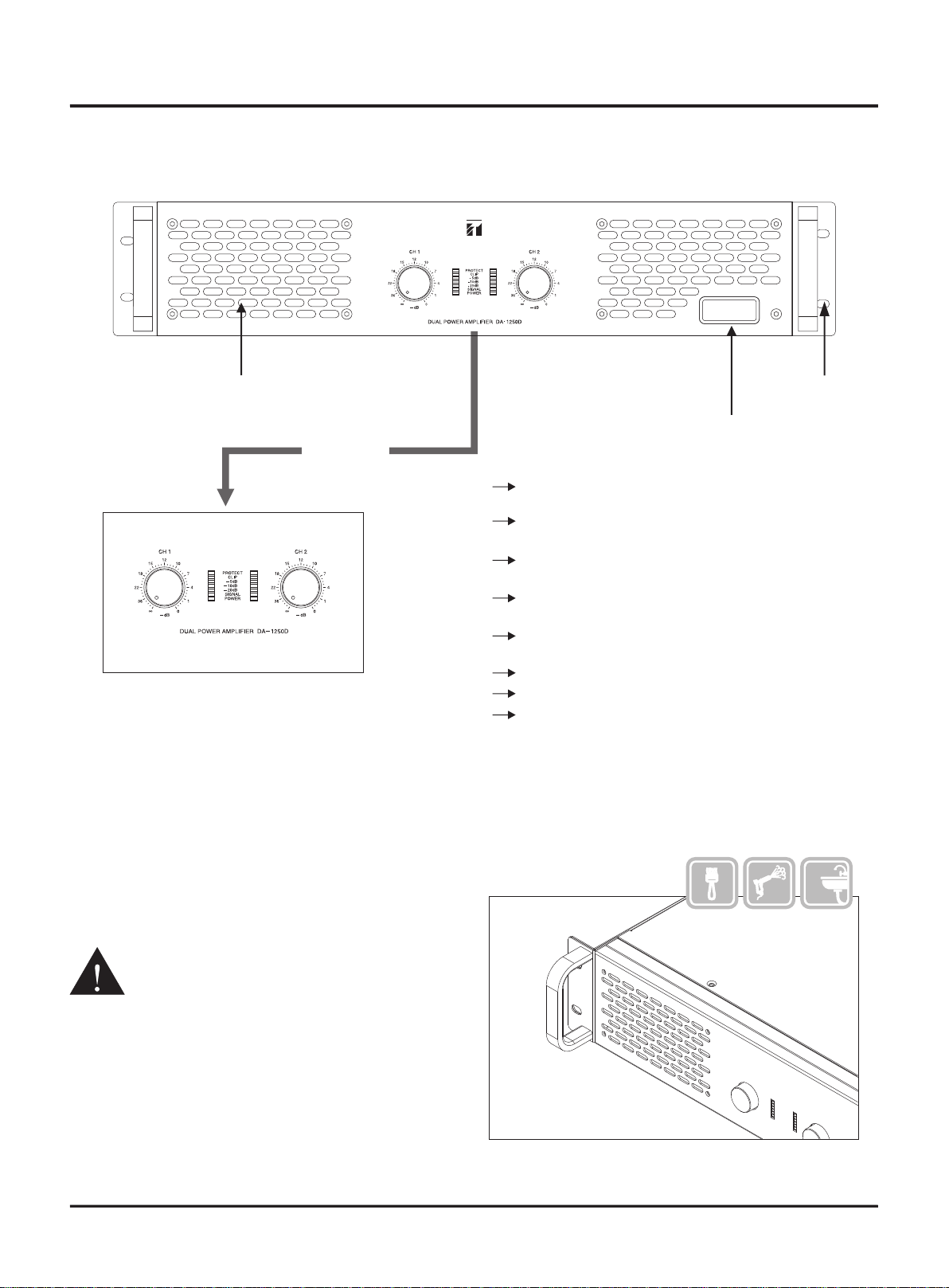
Front panel functions
Front Panel
Suction
Control panel
PROTECT
CLIP
-5dB
-10dB
-20dB
SIGNAL
POWER
CH1-CH2
Mounting hole
Power switch
Illuminates when either protection
circuit action.
Illuminates when compressor / limiter is
protecting the amplifier from input overload.
Illuminates when output signal around -5dB
than full power.
Illuminates when output signal around -10dB
than full power.
Illuminates when output signal around -20dB
than full power.
The signal light
Illuminates when the amplifier start.
Gain Controller Knob
Stereo/Paralle Mode: volumes of CH1 and CH2
control independently.
Bridge Mode: CH1 knob controls both volumes.
Ch1 stops working.
For normal operation, please keep the
controller at max (0dB).
Cleaning guide of the dust filter
The first time cleaning of the strainer mesh
should be right after install at ion.
Recom me nd to clean the strainer mesh
quar terly.
Please do not run the product without the
dust filter, or it makes the service
life of the product shorten.
condition will be conside red as
Such
no warranty.
3/10
Page 5

Rear panel functions
Rear Panel
Socket with f use
FAN
The speaker connector
It can work from 2-16ohm in
stereo or parallel mode. It can
work good from 4ohm to
16ohm In bridge mode
We don't suggest you use the
amplifier under 4ohm bridge
mode for a long time, it will
short its normal use life or have
some unnecessary failure.
Amp output
Signal connection
Mode
selector switch
Signal
connectior
Signal input INPUT
Sensitivity
selector switch
INPUT
Balanced male XLR
Signal output LINK
The quality of your soldering is very
important Virtual welding or
soldering errors,Would be likely to affect
the normal Use or even failure
Speakon(NL4)
4/10
BL AC K
RE D
negative/bla ck/ne ro
CH1
posit ive/red/ro sso
posit ive/red/ro sso
CH2
negative/bla ck/ne ro
Page 6

System connection cases
Speaker Signal source
5/10
Page 7

Wiring and AC power supply
Power & Wiring distribution
The amplifier power supply isn't a non-resistance load and its use on unstable music signal, so it can not
calculate with "Voltage x Ampere=Watt" ,the actual power consumption can not be fixed formula .
Referring to the power dissipation and power supply/AC of different product for wiring
We suggest the users to match not less than the following wiring size specifications, to obtain the better
comprehensive properties.
The Standard Voltage 100-240V:
Model
DA-1250D 1100W ≥1.5mm
Dissipation
Power
Cable size
2
When you use 1 power supply socket for many amplifiers, the power cable of the outlet should be bigger
and also the internal cable of socket.
Please check the powe r voltage remark in the rear panel:
220V/240V = voltage r ange between AC200V to 240V.
Sta bl e power supply voltage ca n en sure the amplifier work s steadily.
The output power will b e ad justed accordin g to the difference voltage of power sup ply
More than one installation
When in the same AC power supply and its total power is more than 10kW, we suggest you use three
phase and five wires in power distribution and the null wire can not use with Ground wire together.
Check after powered
For the first time powered, you have to use the multimeter to measure voltage, and confirm
whether meet the requirements of the product. And do not connect signal and speaker after
you confirm everything is ok, then power off the amplifier.
The importance of Ground wire
You should connect Ground for safety use.
If you don't have qualified Ground connection or not use the Ground, you may have a electricity shock.
To avoid such thing happen, please connect Ground when you use.
6/10
Page 8

Thermal Dissipation
Stack installation
To ensure the cooling environment, please meet the following condition
HOT AIR
>20CM
R
I
In order to have a good heat
dissipation condition for amplifier,
please clean the filter after you finish
your install, because the dust in filter
will stop the air vent, it's not good for
the heat dissipation. And you should
clean the filter net every month.
COOL A
To avoid heat protection
To prevent the hot air back to front air vent
Install exhaust blower
take the hot air away
HOT AIR
COOL A
R
I
The ambient tempera ture should
be lower than 35℃ while ru nn ing
the amplifier
If use in Non-horizontal stack, we
suggest the rear exhaust outlet up
or straight to the vents of the room
Try your best to keep the temperature
under 35℃ even in extreme condition
Keep hot air will not flow
back to the front air vent
CO
O
L A
R
L AI
OO
C
R
I
7/10
Page 9

Power Level adjustment
Procedure
Power On
Sound console Source
Peripheral devices
Power Amplifier
Power off
Power Level Adjustment
Power amplifier should be in the condition of no load in the
following adjustment process:
Process:
Mixer Processor
LINE
GAIN
+40
-10
GAIN
the
Input
stable pink
noise
Adjust input
gain
12
0
CH
Put
the line
output to 0dB
12
0
MAIN
Put
the main
output to 0dB
CLIP
12
6
3
0
3
6
12
20
40
LEVEL
The main output
amplitude set
should be
displayed
as: 0dB
Adjust the
input level of
processor like
the above
picture
CLIP
INPUT
LEVEL
For high power system, the
Power-on order is very important,
not in the order is likely to damage
the equipment. Therefore we
suggest that you use the sequence
power device.
0
3
6
9
12
15
18
40
This is a normal step to adjustment,
for more professional adjustment
you should have a professional
person to do that.
Processor
CLI P
LEVEL
0
3
6
9
12
15
18
40
0
8
-
+12dB
OUTPU T
Adjust the output level of
processor, the range like
the above picture shows
Amp
LEVEL
Adjust the volume kno b
and make the ou tp ut level
within the range as above
picture shows .
Mixer
+40
CLI P
12
6
3
0
3
6
12
20
40
LEVEL
LINE
GAIN
-3dB
-10
GAIN
Then adjust the input
gain to make the main
output less 3dB.
This setting is to ensu re
twice power.
Music Audition
Adjust the volume from very small to loud slowly, after you confirm
the sound is normal then make it more louder. When the speaker
output is close to its limit, the CLIP light will lights up and you
should turn down your volume now, don't let the CLIP lights on long
time, it means over load, may damage the system.
8/10
This step should operated by
professional person, if you don't
know how to do, please be careful!
Page 10

Specifications
Output power
8Ω stereo
4Ω stereo
8Ω bridge
Other Specifications
Frequency response
THD+N
S/N rate
Damping factor
Slew rate
Input sensitivity
Input impedance(bal/unbal)
Voltage gain (8 ohm)
Output circuitry
Cooling
Protection
700Wx2*
1250Wx2**
2500W**
20Hz-20KHz(+/-3dB )
≤0.15%
≥100dB
≥500
≥10V/μs
0.775/1.0V/32dB
20kΩ/10kΩ
39.7dB
Class D
Air flow from front to rear
Soft start
, DC short circuit over load clip limit over heat progressive volume, , , , , , VHF
Connection
Input
Output
Balance input XLR-F, Balance output XLR-M
Two red and black Binding posts, Nl4 SPEAKON
Function
Front panel
Rear panel
Front panel indicator: Working indicator, Signal/Clip/Protection/Power on/-5dB/-10dB/
-20dB / volume control knob
Sensitivity selection s witch Cross-ove r se lection switch、stereo/parallel/bridge/
Dimensions/Weight
Product Dimension(mm)
Packaging Dimension(mm)
G.W.
Power Supply
Remark:
1、*,The power is tested under the condition of 40ms burst,1kHz sine wave and 1% THD
2、**,The power is tested under the condition of 20ms burst,1kHz sine wave and 1% THD
483x305x89
560x430x170
7.7kg
Power Cord
Product dimension(mm)
The manufacturer reserves t he rights to make changes in s pecificatio n without prior notice.
The final specification is subject to the user's m anual.
9/10
Page 11

Troubleshooting
After powered without any response
Measure the outlet with a multimeter to check if there is power
available and when no multimeter, you can have a test pencil.
If the power supply is normal and the amplifier still no response
when powered then there is something wrong with the
amplifier, need professional person to check it.
No signal output
1.Frist check if the signal input is right.
Check the connect of XLR, if the 2 and 3 reverted or the
ground is reliable. Different circuitry design will have different
connect way of the XLR, please follow the 2+、3- to soldering.
It can not be judged by comparing with other amplifiers
(including other amplifiers in the same factory).
2.The signal light don't lights up
If all the signal input is fine and the signal light don't lights up
then may the amplifier has failure, you need to ask the
professional person to check it.
3.Signal input normal but no sound
The signal light will flash with the change of input Volume,
but now sound out, then you can check the connect of speakon
if it is connect good and the wires are connect right(some times
the problem of the wires connect, check its±1 and ±2 connect),
after the check above if still no sound out, please change a
speaker cable and check again. Because some times also caused
by the bad quality of the Speakon connector problem of the
amplifier.
Through experiences, it may caused by the bad connection
of some plugs and the socket.
Output sound distortion
1.After check the signal and loudspeaker they are fine and still
can hear distortion when small sound, then may the amplifier
has failure, need professional person to check it.
2.Some frequency band has distortion
First, check if the loudspeaker already overload, normally
judge it in 95~105dB for higher SPL we don't comment here.
Here we just think about the failure recovery of the amplifier.
If in the middle have some rupture sound and more smaller
volume more obvious, then it should be crossover distortion
of the amplifier and this kind of distortion is easy to confuse
with the failure of loudspeaker itself. If the amplifier have
problem then you should send back to the manufacture for
repair.
3.Distortion is High SPL
If the sound is normal when small volume and then you need
to check the limit SPL of the loudspeaker. You can listen it in
suitable volume and if clip light works, then you need reduce
the output. Both loudspeaker and amplifier have limit, you
should use them in their limit if in very high SPL they have
distortion you should take care of them and reduce the output
to the right position.
The protection light blinks
When the PROTECT light works, the amplifier into the
protection mode.
1.Maybe the temperature is too high or output short or near
short and they are not failure they can recovery after you can
use it normally. But over heat will take more time to recovery.
Also when over heat happened you should check the fan and
the temperature of the install environment, if does you should
solve the problem then can use amplifier. If you think the
speaker was short, you can with a multimeter to check if the
resist is lower than 2 ohm or 1 ohm with DC(Please calibrate
the multimeter to measure for accuracy because of the small
resistance).
2. If the PROTECT light always light up then it should be the
problem of amplifier, you should send it back to professional
person for repair.
Hum in the system
1. Hum exists even when there is no signal
Please keep the amplifier away from earth wire of power supply
cables, just connect the fire wire and zero wire, no ground wire.
If the hum is still existing, it can be judged that there are some
problems in the amplifier. Please get in touch with professionals.
2. Hum exists when the system is completely connected
This is caused by the different ground voltages in difference
devices in the system, mainly happens when the power supply
is under three-phase distribution condition, each device is
connected to different phase. This is not caused by amplifier.
Solution experiences, just for reference
A. Combing the electricity, the power distribution box using the
same one for all if possible.
B. Make sure the grounding wire potential is zero and force the
different grounding wire to the same level, if the grounding
wire Itself charged, indicates that the wire may be connected
with the zero line. Please solve this problem.
C. If unavailable above, then only to disconnect the ground
wires of all devices, which helps to reduce the AC. But this is
not meet the safe use of electricity, users must know what
will happen if to do in this way. We do not recommend the
floating use.
The amplifier is required maintenance in the
condition below:
1. If the amplifier smokes or smells burning.
2. If the cabinet has severe indentation and deformation
3. If the amplifier are dipped into the water
4. If the internal components loosen
5. If AC breaker skips out when current increases.
10/10
Page 12

 Loading...