

Page 1
INSTRUCTION MANUAL
D-901 PC SOFTWARE Version 3
Please follow the instructions in this manual to obtain the optimum results from this unit.
We also recommend that you keep this manual handy for future reference.
Page 2

2
TABLE OF CONTENTS
1. GENERAL DESCRIPTION ............................................................................. 5
2. INSTALLATION .................................................................................................. 6
3. STARTING THE SOFTWARE ........................................................................ 8
4. MAIN SCREEN ................................................................................................... 9
4.1.Menu Term Description
4.1.1. File ......................................................................................................... 10
4.1.2. Edit ......................................................................................................... 10
4.1.3. View ....................................................................................................... 10
4.1.4. Unit ......................................................................................................... 10
4.1.5. Memory .................................................................................................. 11
4.1.6. Remote .................................................................................................. 11
4.1.7. Option .................................................................................................... 11
4.1.8. Help ........................................................................................................ 11
5. CONFIGURATION SETTINGS
5.1. D-901 System Configuration ............................................................................ 12
5.2. Changing the Crossover Combinations ........................................................... 16
5.3. Changing the Crossover Slopes ...................................................................... 16
5.4. Changing Equipment Names ........................................................................... 16
5.5. Storing the Configuration as a Template .......................................................... 16
5.6. Storing the Crossover Settings as a Template ................................................. 16
6. MEMORY VIEW ................................................................................................ 17
7. FLOW VIEW ....................................................................................................... 18
8. CONTENTS VIEW
8.1. Matrix View (Bus Assignment and Crosspoint Gain Setting) ........................... 19
8.2. Trim View (Input Trim Settings) ........................................................................ 20
8.3. HPF/PEQ View (High-pass Filter/Equalizer Settings) ...................................... 21
8.4. Comp/Leveler View (Compression/Auto-leveler Function Settings)
8.4.1. Compression function settings ............................................................... 23
8.4.2. Auto-leveler function settings (available only to the input channel) ....... 25
8.5. Automix View (Auto-mixing Function Settings)
8.5.1. Gate function settings ............................................................................ 27
8.5.2. NOM attenuation function settings ......................................................... 30
8.5.3. Ducker function settings ......................................................................... 31
8.6. Fader View (I/O Gain and I/O Group Trim Settings)
8.6.1. I/O gain settings ..................................................................................... 32
8.6.2. I/O group trim settings ............................................................................ 33
8.7. Filter View (Filter Function Settings) ................................................................ 34
8.8. Xover View (Crossover Function Settings)
8.8.1. Crossover function settings .................................................................... 36
8.8.2. Time correction settings between Xover boxes ..................................... 39
8.9. Delay View (Delay Function Settings) .............................................................. 40
8.10. Effect/Echo View (Effect/Echo Function Settings) ......................................... 41
8.11. FBS View (Feedback Suppression Function Settings) .................................. 42
8.12. Microphone/Line Input Module View
(Available only when the D-921E or D-921F is used) .................................... 43
Page 3

3
8.13. Digital Input Module View (Available only when the D-923AE is used) .. 44
8.14. Stereo Input Module View (Available only when the D-936R is used) .... 45
8.15. Digital Input Module View (Available only when the D-937SP is used) .. 46
9. RESPONSE VIEW
9.1. Output Response View .................................................................................... 47
9.2. Xover Response View ...................................................................................... 48
10. PRESET MEMORY SETTINGS
10.1. Recalling the Preset Memory ......................................................................... 50
10.2. Writing Data into the Preset Memory ............................................................. 50
10.3. Preset Memory Crossfade Time Setting ........................................................ 51
10.4. Changing the Name ....................................................................................... 51
10.5. Setting the Preset Memory Recalled When Power Is Turned On .................. 52
11. STEREO LINK SETTINGS
11.1. Stereo Link Functions .................................................................................... 53
11.2. Stereo Link Settings ....................................................................................... 53
11.3. Stereo Link Reset .......................................................................................... 53
11.4. Stereo Link Setting Restrictions ..................................................................... 53
12. LEVEL MONITOR VIEW ................................................................................. 54
13. COMMUNICATIONS ........................................................................................ 55
14. USER LEVEL
14.1. What Is the User Level? ................................................................................. 58
14.2. Enabling the User Level ................................................................................. 58
14.3. Logging On When the User Level Is Enabled ................................................ 59
15. RESTRICTION SETTINGS ............................................................................ 60
16. PRINT ................................................................................................................... 63
17. SETTINGS REQUIRED WHEN THE D-981, D-983, OR D-984VC IS
USED
17.1. The Outline of the D-981, D-983, and D-984VC ............................................ 64
17.2. Contact Input Setting Screen ......................................................................... 64
17.3. Contact Input Function Assignment
17.3.1. Memory selection ............................................................................... 65
17.3.2. Input/output volume adjustment ......................................................... 66
17.3.3. Channel ON/OFF ............................................................................... 67
17.3.4. Stereo input ....................................................................................... 68
17.4. Contact Output Setting Screen ...................................................................... 69
17.5. Contact Output Function Assignment
17.5.1. Memory selection ............................................................................... 70
17.5.2. Channel ON/OFF ............................................................................... 71
17.5.3. Contact input status ........................................................................... 72
17.5.4. Stereo input ....................................................................................... 73
18. PROTECT FUNCTION SETTINGS ............................................................. 74
Page 4

4
19. VIEW DISPLAY SWITCHING (SUPPLEMENT)
19.1. Docking Displays ........................................................................................... 76
19.2. Floating Displays ............................................................................................ 77
20. SPECIFICATIONS
20.1. Software Specifications .................................................................................. 78
20.2. Communication Specifications ....................................................................... 78
20.3. Setting Items and Setting Ranges
20.3.1. Signal processing box ........................................................................ 78
20.3.2. Auto mixing function .......................................................................... 82
20.3.3. Settings when the D-921E or D-921F is used ................................... 82
20.3.4. Settings when the D-936R is used .................................................... 83
20.3.5. Settings when the D-937SP is used .................................................. 83
20.3.6. Settings when the D-981, D-983, or D-984VC is used ...................... 83
20.3.7. Preset Memory Settings .................................................................... 83
Page 5

5
1. GENERAL DESCRIPTION
The PC software is designed for exclusive use with the D-901 Digital Mixer. It performs settings visually and
more simply than those made at the D-901 unit. It runs on the following operating systems: Microsoft Windows
98 SE, Windows Me, Windows 2000 and Windows XP.
A PC with a display set at high color (16 bits) or higher is recommended for use with this software.
Note
Windows is the trademark of Microsoft Corporation.
Page 6
6
2. INSTALLATION
Terminate all other application programs in operation before installation.
Follow the procedures below to install.
Step 1. Download the installation program (D901PCv300E_f300.exe) from TOA's homepage (http://www.toa-
products.com/international/) and save it to the desktop.
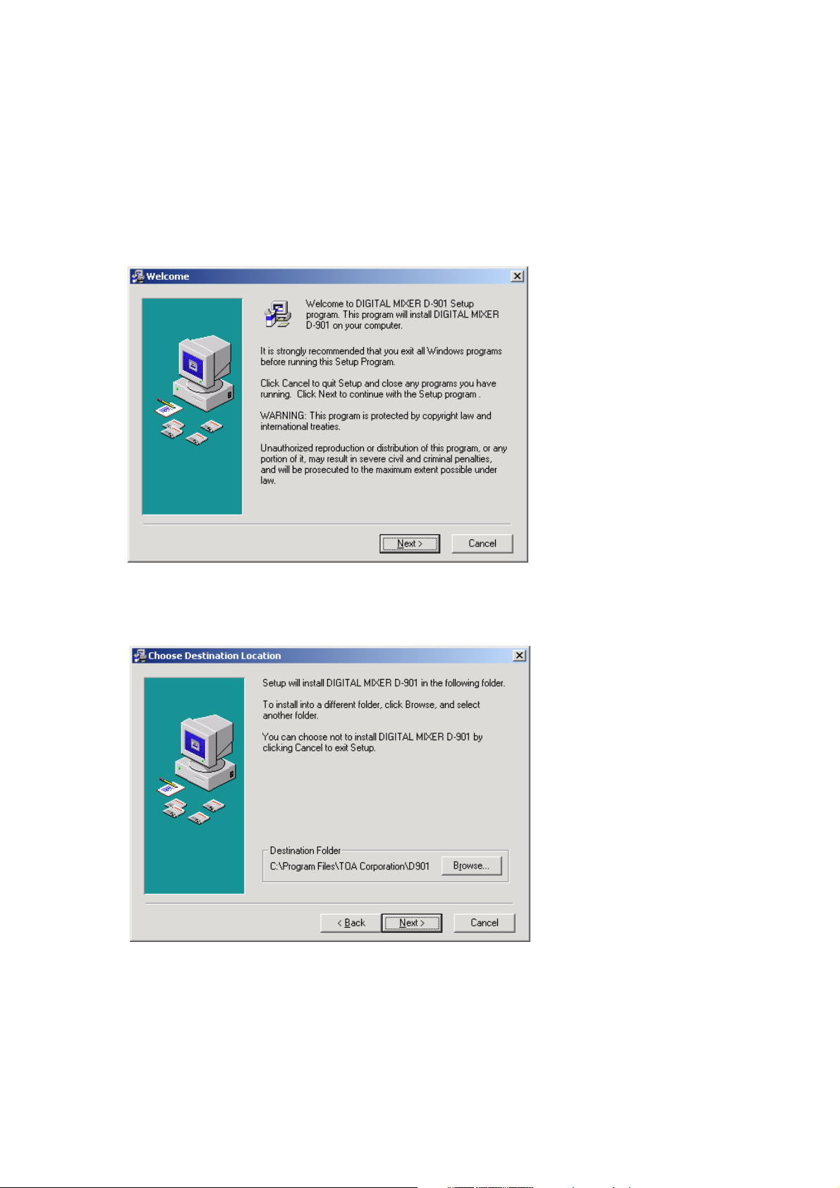
Step 2. Double-click the install program icon.
The following window is displayed.
Step 3. Click the [Next] button.
The following window is displayed.
Page 7
7
Step 4. If necessary, change the folder into which the software will be installed, then click the [Next] button.
The following window is displayed.
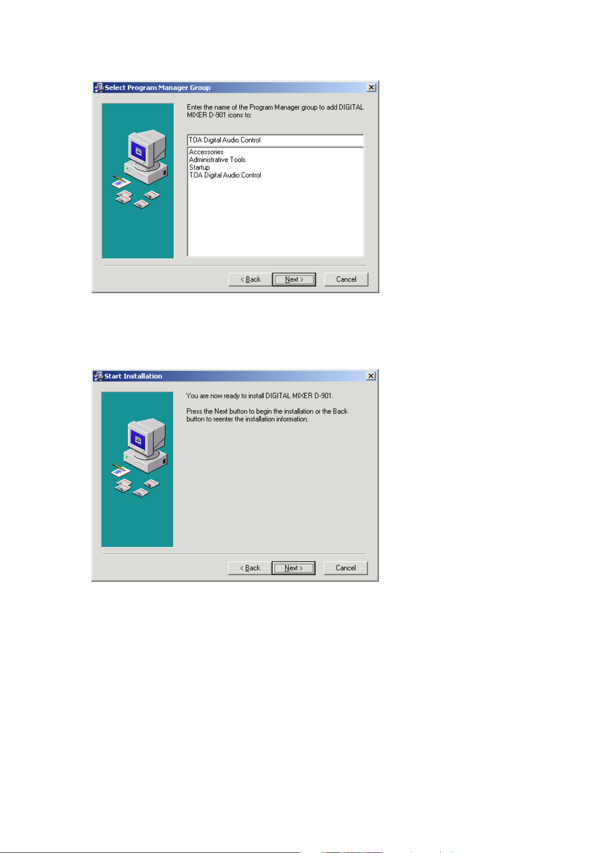
Step 5. If necessary, change the name of the Program Manager group and click the [Next] button.
Step 6. Start installation according to the instructions on the screen.
Step 7. Click the [Finish] button after installation completion.
The shortcut icon for the D-901 PC Software executable file is stored in the PC's start menu .
Page 8
8
3. STARTING THE SOFTWARE
The following two different methods are available for starting the installed D-901 PC Software:
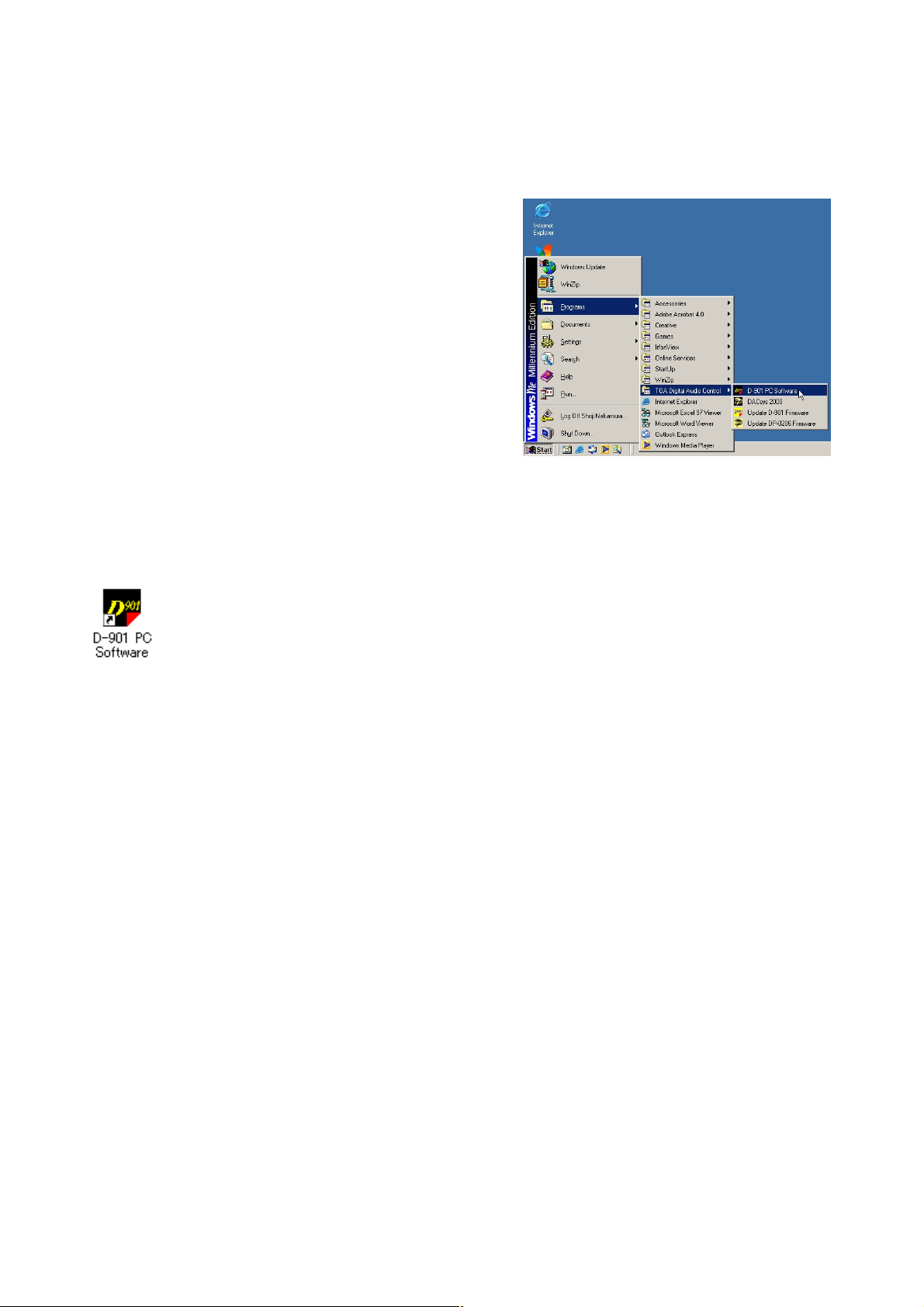
(1) Starting from the [Start] button
You can start the D-901 PC Software from the start menu.
Press the [Start] button on the PC's desktop, and select
[Programs → TOA Digital Audio Control → D-901 PC
Software] to start.
(2) Starting from the shortcut icon
After installation completion, drag the "D-901 PC Software" icon displayed on the file the software was
installed in to the desktop to copy it while holding down the [Ctrl] key. The shortcut icon is then created on the
desktop.
Double-click this icon to start the software.
Page 9
9
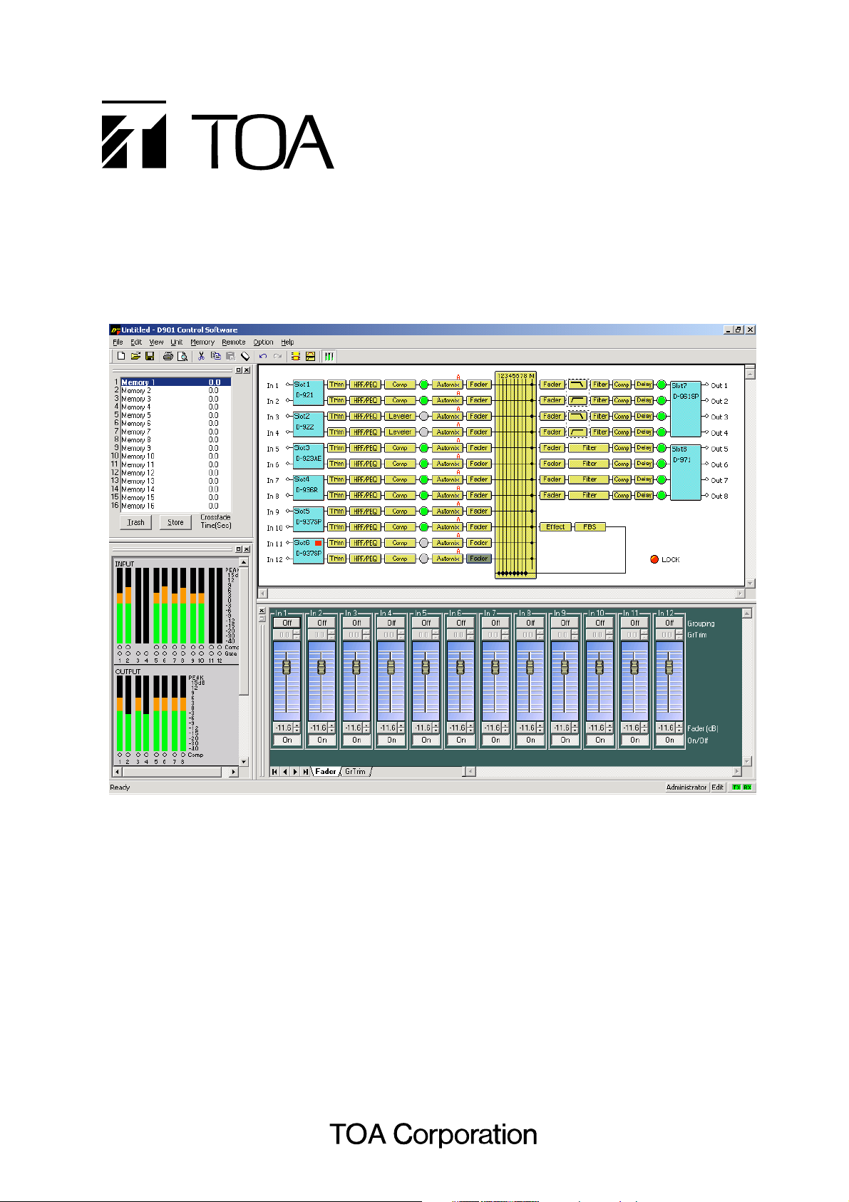
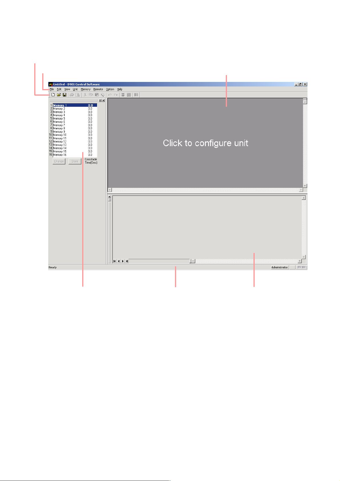
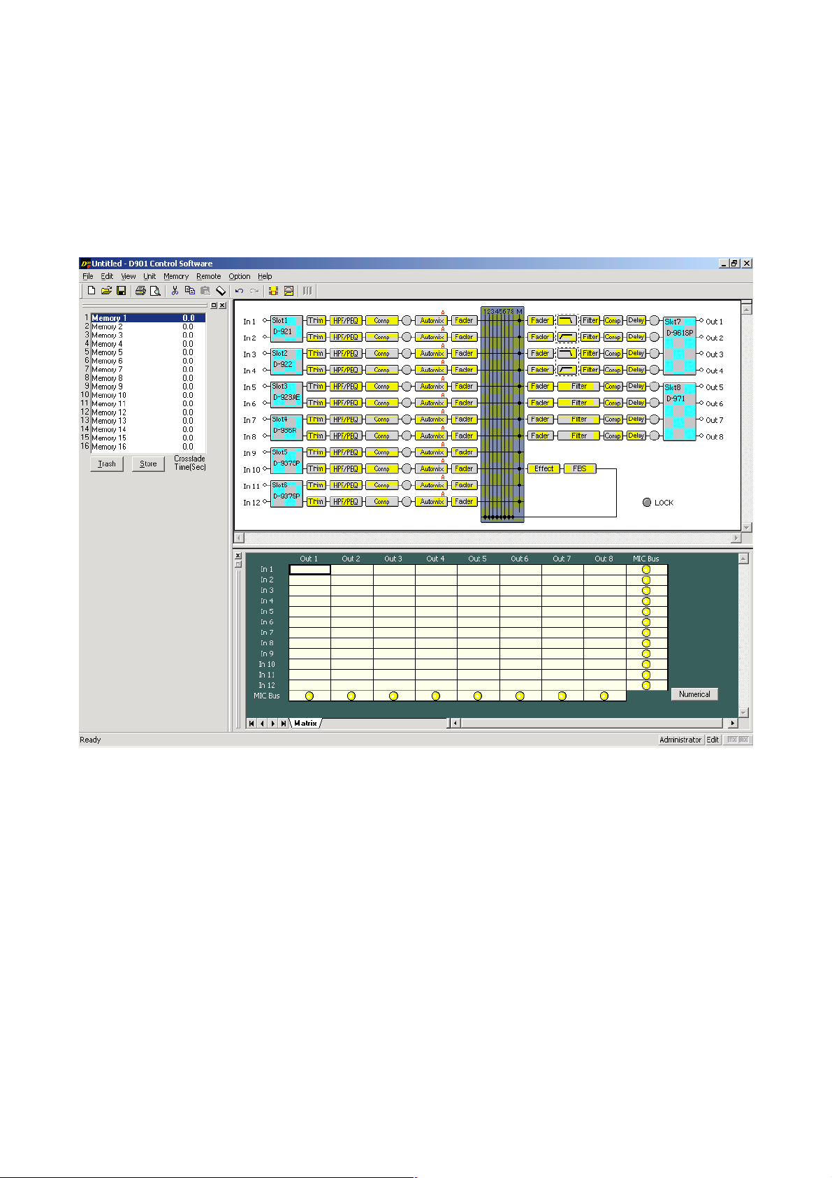
4. MAIN SCREEN
Starting the D-901 PC Software causes the main screen to appear.
Toolbar
Menu (see p. 10)
Flow view (see p. 12 and p. 18)
Memory view (see p. 17) Status bar Contents view (see p. 19)
Page 10

10
4.1. Menu Term Description
4.1.1. File
New: Creates (sets) a new data file.
Open... : Calls up the existing data file.
Save: Overwrites the file being edited.
Save As... : Saves the file being edited to the disk under a different name.
Page Settings... : Changes the margin produced during printing.
Print... : Prints the document onscreen.
Print Preview: Displays a preview of the document.
Exit: Exits the D-901 PC Software.
4.1.2. Edit
Undo: Returns the previous change to the original status.
Redo: Repeats processing previously performed again.
Cut: Initializes the setting value after copying the setting value of the designated box
to the clipboard.
Copy: Copies the setting value of the designated box to the clipboard.
Paste: Pastes the clipboard data to the designated box.
Clear: Initializes the setting value of the box.
Enable Stereo Link ... : Performs the stereo link setting of the channel.
Disable Stereo Link: Resets the stereo link setting of the channel.
Write Protect to Box
Off: Does not restrict writing in the box.
Low: Prohibits box parameter changes by operators.
Mid: Prohibits all box changes by operators.
High: Prohibits box parameter changes by administrators, and all changes by
operators.
4.1.3. View
Toolbar: Shows or hides the toolbar.
Status Bar: Shows or hides the status bar.
Contents View: Shows or hides the contents view.
Response View: Shows or hides the response view (see p. 47).
Memory View
Show/hide: Shows or hides the memory view.
Floating: Floats the memory view window.
Docking: Docks the memory view window.
Level Monitor View: Shows or hides the level monitor view.
4.1.4. Unit
Change Unit Configuration... : Performs configuration settings.
Change X-over
Combination... : Changes crossover combinations.
Slope... : Changes crossover slopes.
Names... : Changes the names of the D-901 Mixer and its inputs and outputs.
Save as a Unit Template...
Unit Template... : Stores equipment configuration settings as a template.
X-over Template: Stores crossover settings as a template.
Page 11

11
4.1.5. Memory
Change
Memories 1 – 16: Makes a call from 16 preset memories.
Store
Memories 1 – 16: Writes setting status in one of 16 memories.
Crossfade Time: Sets the crossfade time when the currently selected preset memory is
switched over to a newly recalled one.
Names: Changes the name of preset memory.
Power ON
Last Memory, Memories 1 – 16: Select the preset memory to be recalled when the D-901's power is turned
on from the Last Memory or 16 memories.
If you select the Last Memory, the PC starts with the last recalled preset
number before turning off the power.
4.1.6. Remote
Connect... : Connects the D-901 to a PC for online processing.
Disconnect: Disconnects the C-901 from a PC for offline processing.
Note
The D-901's setting does not change while in the offline state even if it is
changed with a PC.
Bulk transmission: Transmits data of the currently opened file to the D-901.
Bulk receiving: Receives the D-901's data.
Auto connection: Makes an automatic connection when the file is opened next time.
Firmware: Displays the D-901's firmware version number. (Only valid when
connected online.)
Comm Setting (S): Performs the COM port's communication settings.
4.1.7. Option
Security Settings... : Performs user level settings and restricted operation settings.
External Control...
Contact input: Sets the contact inputs of the D-981 or D-983 Remote Control Module, or
the D-984VC VCA Control Module.
Contact output: Sets the contact outputs of the D-981, D-983, or the D-984VC.
Protect Settings: Performs the D-901's front panel protection settings.
4.1.8. Help
About... : Displays the D-901 PC Software version number.
Page 12
12
5. CONFIGURATION SETTINGS
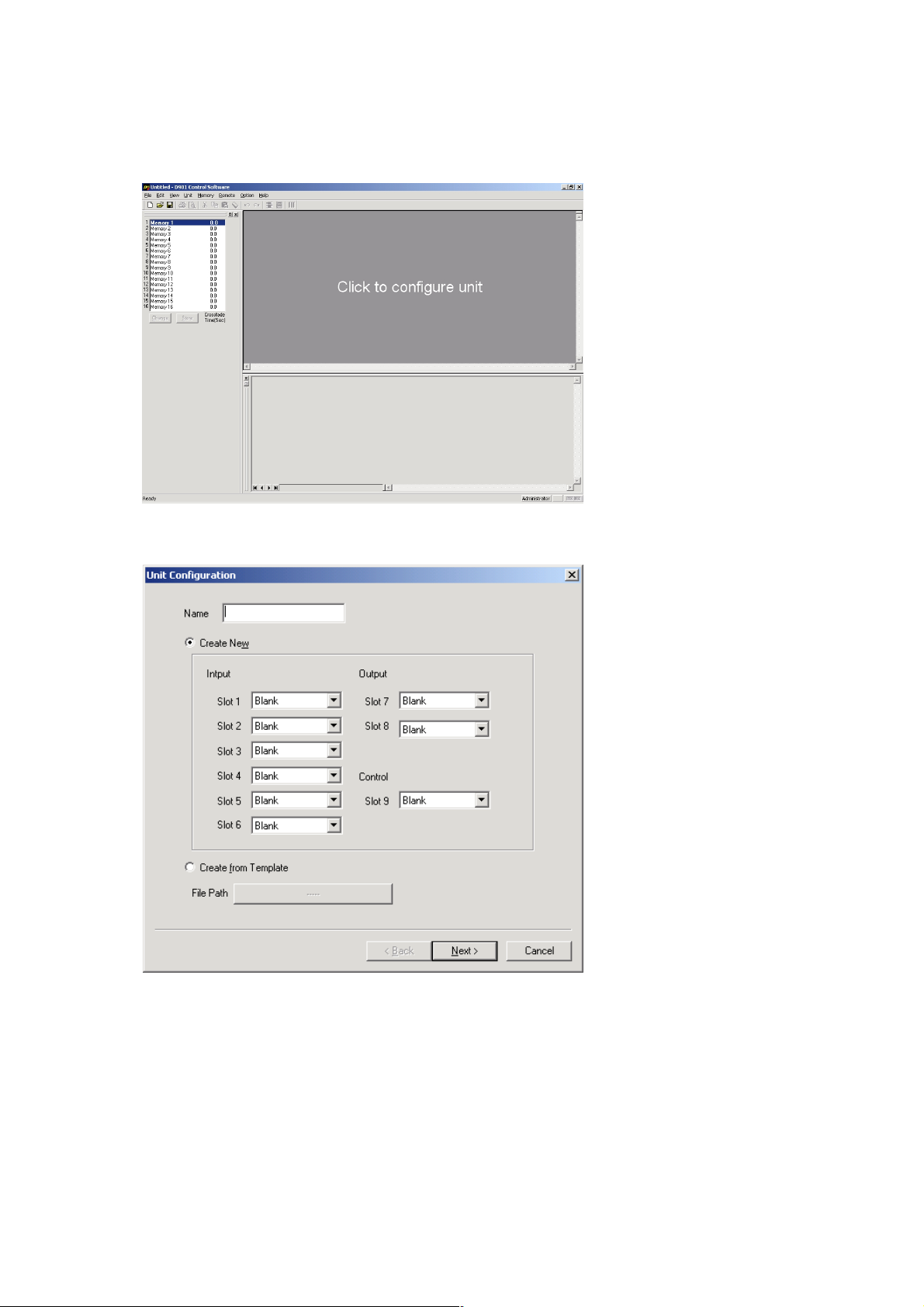
5.1. D-901 System Configuration
Step 1. Click "Click to configure unit" on the main screen.
The Unit Configuration setting screen is displayed.
Step 2. Enter a unit name.
A maximum of 20 characters can be used.
Page 13
13
Step 3. Select the input, output, control modules.
Notes
• In initial status, "Create New" is selected, and all module column boxes are left "Blank."
• To create from the template (see p. 16), select "Create from Template" and click the [Click Here]
button displayed in the File Path field. A dialog box for selecting the file is then displayed. If you
select the file and click the [Finish] button, the signal flow (see p. 15) is displayed.
Caution
Both the D-971E and the D-971M Line Output Modules can be mounted for only a maximum of 2
units in all. The D901 PC Software does not distinguish types of output modules. However, take care
about the output module combinations when mounting them in the D-901 mixer.
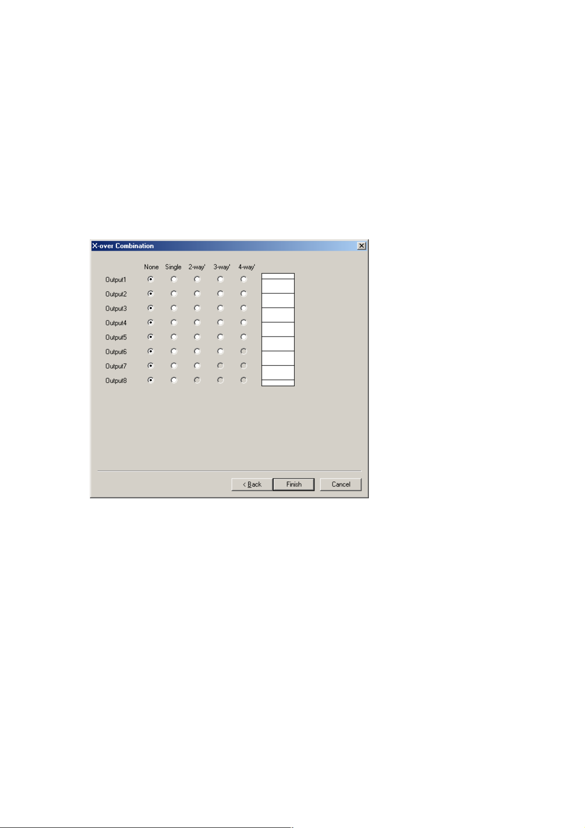
Step 4. Click the [Next] button.
The Crossover Combination screen is displayed.
Page 14
14
Step 5. Click the setting contents to perform the crossover combination settings.
Setting status is displayed in the window on the right side of the screen.
[2-way/2-channel setting example]
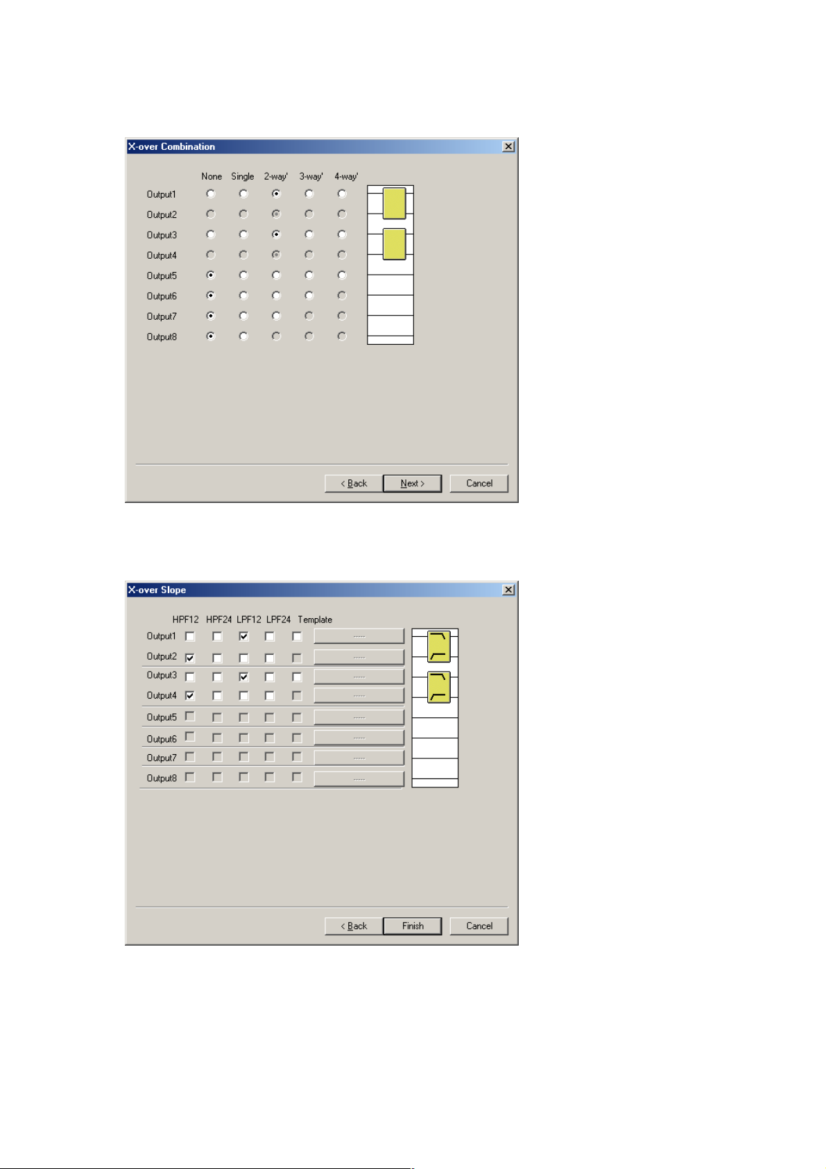
Step 6. Click the [Next] button.
The Crossover Slope screen is displayed.
Page 15
15
Step 7. Tick the checkboxes for the crossover slope settings.
Setting status is displayed in the window on the right side of the screen.
Note
When using the template (see p. 16), tick "Template" box and click the [Click] button located on the
right side of a checkbox. A dialog box for selecting the file is then displayed. If you select the file and
click the [Finish] button, the signal flow (see below) is displayed.
Step 8. Check to ensure that the setting is correct and press the [Finish] button.
The signal flow is displayed.
Page 16
16
5.2. Changing the Crossover Combinations
You can change the configuration crossover combinations already created.
Select [Unit → Change X-over → Combination...] from the menu to display the Crossover Combination
screen.
Crossover combination settings can be changed by way of the same procedures used for unit creation.
5.3. Changing the Crossover Slopes
You can change the configuration crossover slopes already created.
Select [Unit → Change X-over → Slope...] from the menu to display the Crossover Slope screen.
Crossover slope settings can be changed by way of the same procedures used for unit creation.
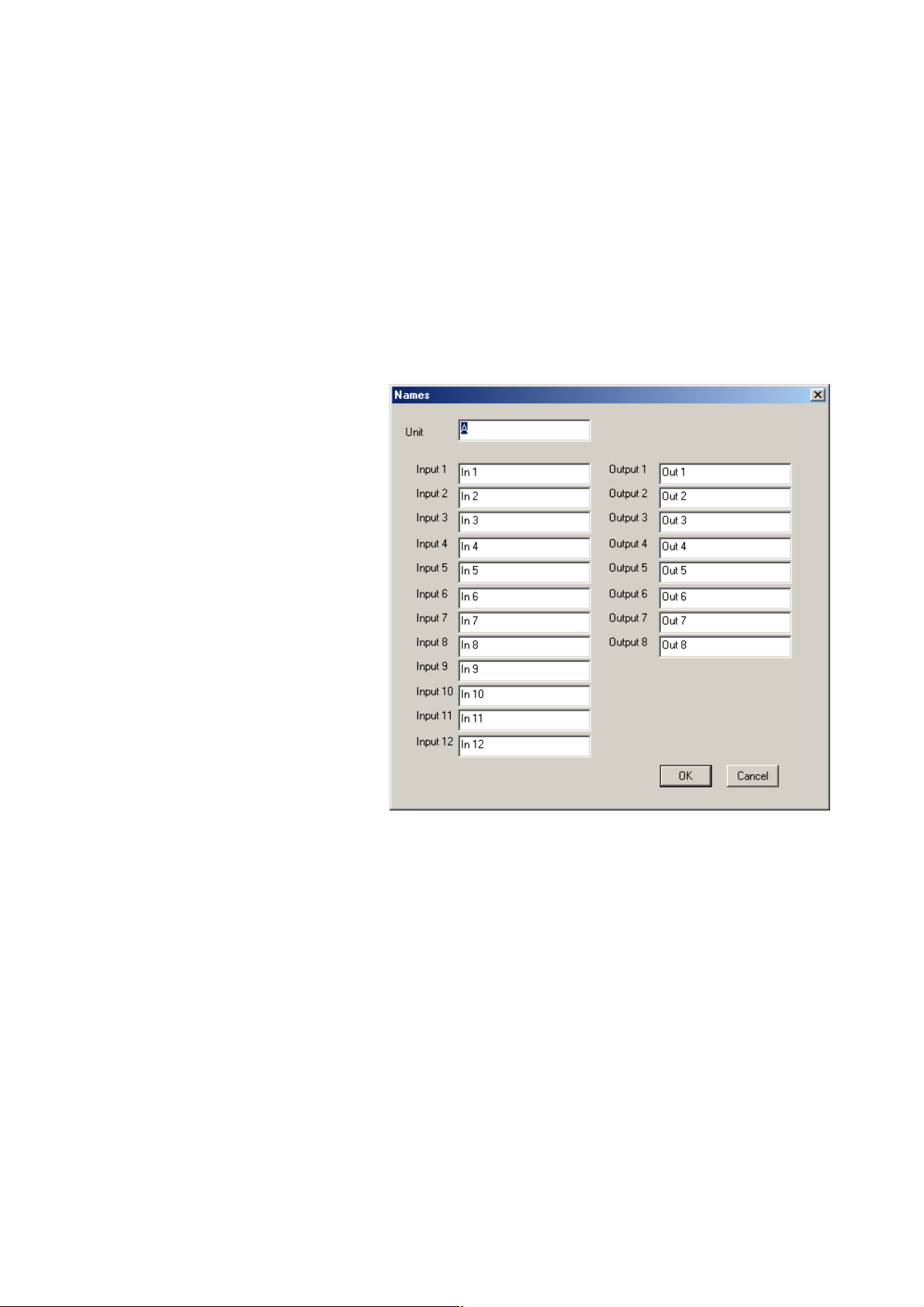
5.4. Changing Equipment Names
Select [Unit → Names] from the menu. A
dialog box for name assignment is
displayed, allowing the D-901 mixer and
input/output names to be changed.
Note
A maximum of 20 characters can be
used.
5.5. Storing the Configuration as a Template
Select [Unit → Save as a Unit Template... → Unit Template...] from the menu. Since a dialog for saving the file
is displayed, assign a name and save.
5.6. Storing the Crossover Settings as a Template
Select [Unit → Save as a Unit Template → X-over Template] from the menu. Since a dialog for saving the file
is displayed, assign a name and save.
Page 17
17
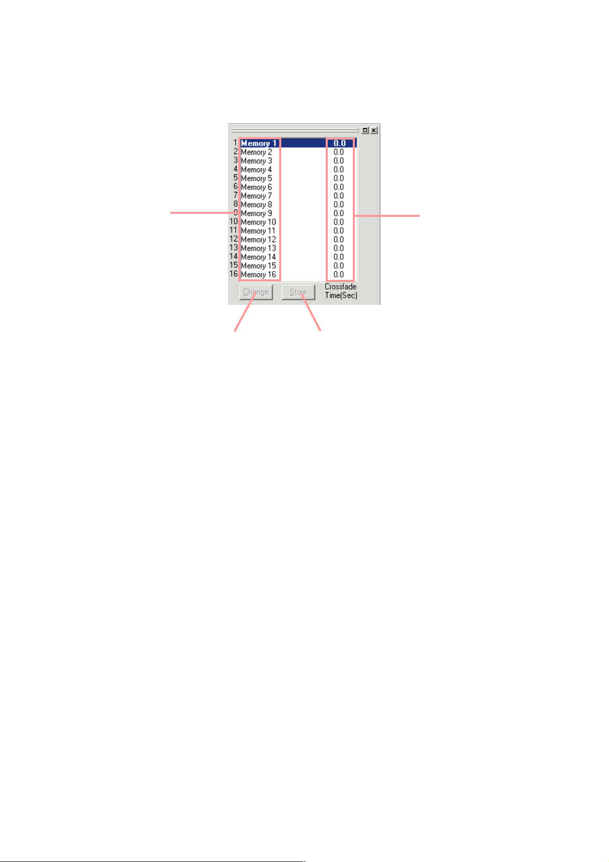
6. MEMORY VIEW
The memory view is located at the upper left of the main screen.
It shows the preset memory names, the crossfade time, and the preset memory numbers being currently
selected. It is possible to recall preset memories and also to write data into the preset memories.
Memory list
Change button Store button
• The preset memory being currently selected is highlighted in the memory list.
• To recall a preset memory, click the corresponding preset memory number and press the [Change] button.
The menu bar can also be used to recall (See p. 50).
• The [Change] button turns to the [Trash] button when the recalled preset memory data is edited. Pressing
the [Trash] button discards the data in edit and recalls the original data.
• To write data into the preset memory, click the corresponding preset memory number and press the [Store]
button. The menu bar can also be used to recall (See p. 50).
• To change a preset memory name or crossfade time, click on it with the corresponding preset memory in the
memory list highlighted by double-click. The preset memory name or crossfade time can also be changed
using the commands from the menu bar. (See p. 51)
A maximum of 20 characters can be used for entering a preset name.
Set the crossfade time for up to 10 seconds in 0.5-second units.
• You can switch the memory view between docking and floating displays*.
[Docking display]
Select [View → Memory View → Docking] from the menu.
[Floating display]
Select [View → Memory View → Floating] from the menu.
* Refer to p. 76 View Display Switching.
Crossfade time
Page 18
18
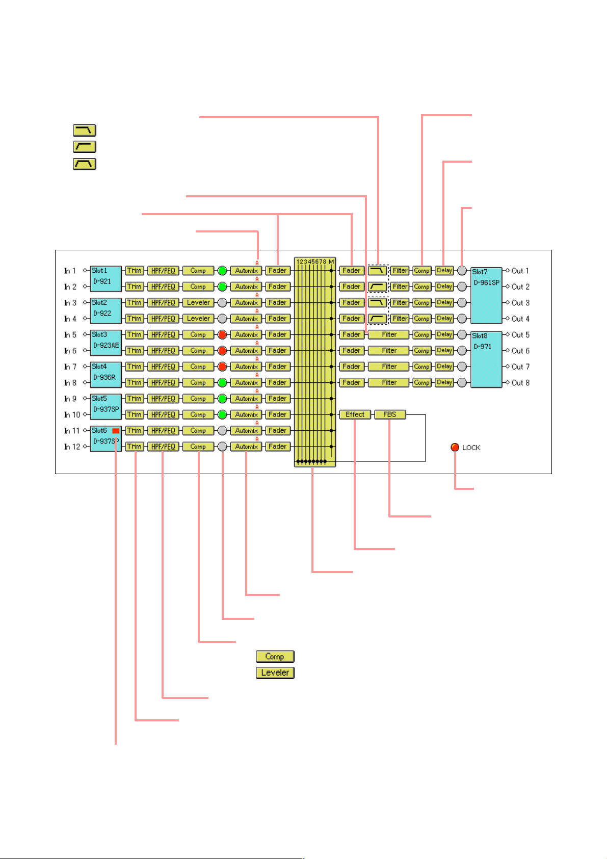
7. FLOW VIEW
The flow view displays a block diagram that shows the signal-processing image of D-901 using functional
boxes.
Matrix (See p. 19.)
Compressor
(See p. 23.)
Delay
(See p. 40.)
Signal indicator *
1
High-pass filter/parametric equalizer (See p. 21.)
Lock indicator *
2
Feedback suppression
function (See p. 42.)
Effect/Echo (See p. 41.)
Trim (See p. 20.)
Auto mixing function (See p. 27.)
Signal indicator *
1
Compressor (See p. 23) / Auto-leveler (See p. 25.)
: When the compressor mode is selected.
: When the auto-leveler mode is selected.
*1Indicates input/output signal levels as follows:
Lights red when a signal level is over 17 dB above the rated level.
Lights green when a signal level is between 40 dB below and 17 dB
above the rated level.
Lights gray when a signal level is over 40 dB below the rated level.
*
2
Lights red if the protect function is enabled.
Crossover (Xover) (See p. 36.)
: Low-pass filter
: High-pass filter
: Band-pass filter
(High-pass filter + low-pass filter)
Multi-band filter (See p. 34.)
Fader (See p. 32.)
Auto mixing group (See p. 27.)
Channel error status indicator
(See p. 44, 46)
Lights red when an error
has occurred, which is valid
only when the D-923AE or
D-937SP is used.
Page 19
19
8. CONTENTS VIEW
Clicking the box in the flow view causes the corresponding contents view to be displayed under the flow view.
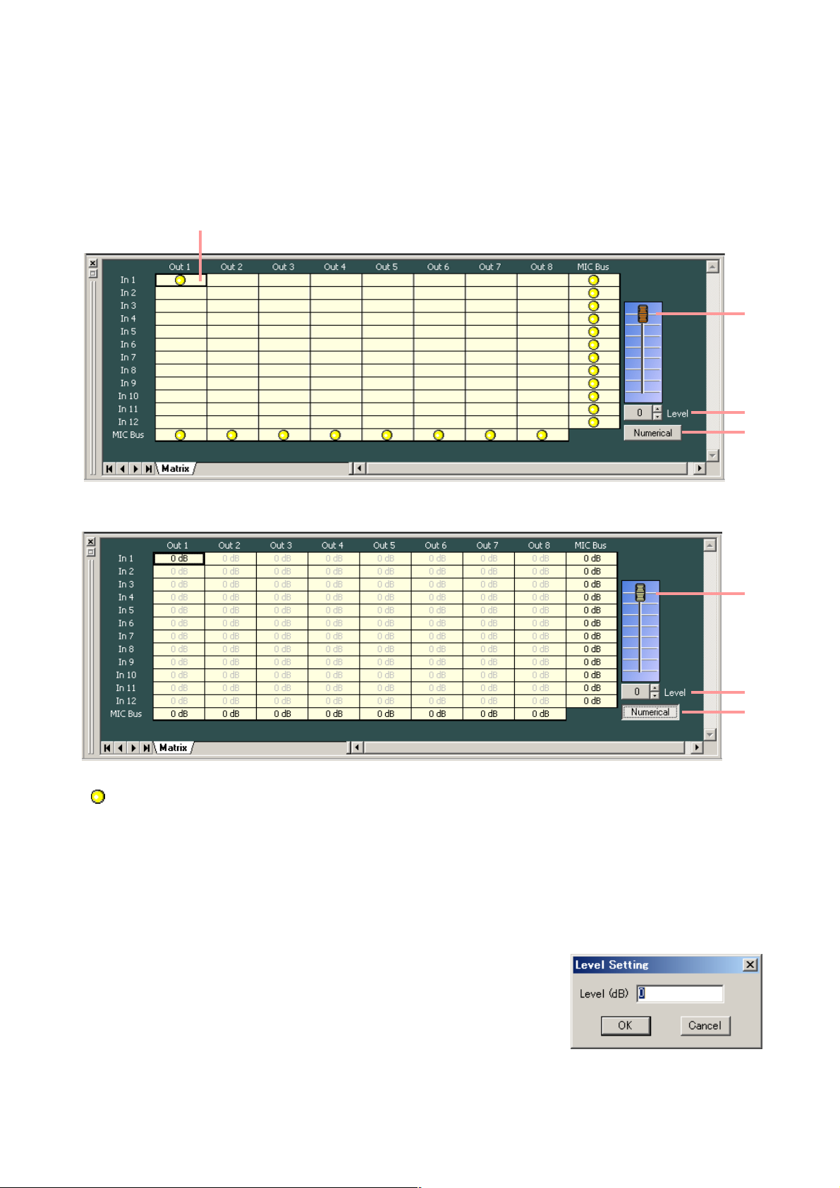
8.1. Matrix View (Bus Assignment and Crosspoint Gain Setting)
The matrix view is displayed if you click the [Matrix] box.
Crosspoint being selected
• indicates input and output signal routings.
• A black, thicker frame indicates the crosspoint being selected.
• The crosspoint turns on and off as it is double-clicked.
(Displayed in numerical form)
(1) Fader
If you select the Crosspoint set to on, the corresponding Fader is displayed.
You can change the signal level at the selected Crosspoint by moving this fader up or down.
(2) Level setting button [Level (dB)]
If you select the Crosspoint set to on, the corresponding Level setting
button [Level (dB)] is displayed.
Indicates the signal level at the selected Crosspoint by means of
numerical values.
If you press this button, a dialog for level setting is displayed, enabling
you to set the level by directly entering a numerical value.
Setting Range: –∞ (–70) to 0 dB
You can also change the level in 1 dB units with the UP and Down
buttons located on the right side.
(1)
(2)
(3)
(1)
(2)
(3)
Page 20
20
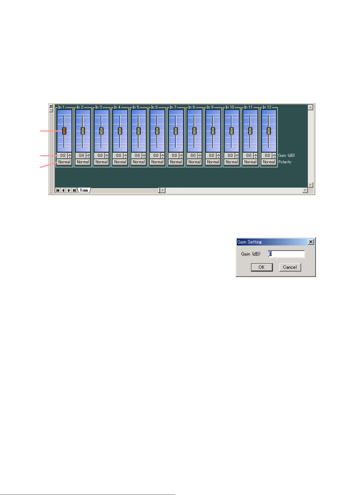
8.2. Trim View (Input Trim Settings)
The Trim view appears if you click the [Trim] box .
(1) Fader
You can change the signal level of each channel by moving this fader up and down.
(2) Gain indication button [Gain (dB)]
Indicates each channel signal level by means of a numerical value.
If you press this button, a dialog for gain setting is displayed, enabling
you to set the gain by directly entering a numerical value. (Setting
range: –15 to +15 dB)
You can also change the gain in 0.1 dB units with the Up and Down
buttons located on the right side.
(3) Reverse polarity button [Polarity]
Displays each channel's polarity. Pressing this button permits the polarity to be reversed.
(1)
(2)
(3)
(3) Numerical value indication selection button
Indicates the level setting at each Crosspoint by means of a numerical value if this button is pressed.
To return the screen to the graphic display, press this button again.
Page 21
21
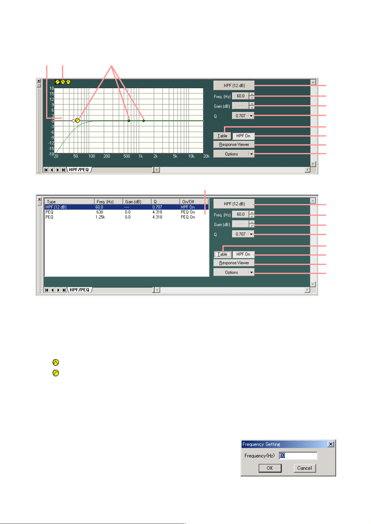
8.3. HPF/PEQ View (High-pass Filter/Equalizer Settings)
The HPF/PEQ view is displayed if you click the [HPF/PEQ] box of High-pass Filter/Parametric Equalizer.
(1) (2) (3)
(4)
(5)
(6)
(7)
(8)
(9)
(10)
(11)
(Displayed in tabular form)
(4)
(5)
(6)
(7)
(8)
(9)
(10)
(11)
(1)
(1) Filter control
(2) Filter point list
(3) Filter point
Circles on the filter control window indicate operable filter points. Yellow circles refer to the selected filter
points.
: Parametric equalizer (PEQ)
: High-pass filter (HPF)
To change the frequency and gain, drag the filter point.
When a white circle is displayed on the left of the filter point, click and drag the white circle up and down.
The Q value of the selected filter point can then be changed.
(4) Filter type indication button
Displays the type of filter.
(5) Frequency indication button [Freq. (Hz)]
Displays the frequency of the selected filter point.
If you press this button, a dialog for frequency settings is displayed,
enabling you to set the frequency by directly entering a numerical
value. (Setting range: 20 – 20,000 Hz)
You can also change the frequency in 1/24 octave units (step width
can be changed with the Option button) using the Up and Down
buttons located on the right side.)
Page 22
22
(6) Gain indication button [Gain (dB)]
Displays the gain of the selected filter point. If you press this button, a
dialog for gain setting is displayed, enabling you to set the gain by
directly entering a numerical value. (Setting range: –15 to +15 dB)
You can also change the gain in 0.5 dB units (can be changed to 0.1
dB units with the Option button) with the Up and Down buttons
located on the right side.
(7) Q indication button
Displays the Q value of the selected filter point.
Pressing this button permits setting values to be selected from the pull-down menu.
(8) Table display button
If this button is pressed, the filter control is displayed in tabular form. Press this button again to return to
the original graphic display.
(9) Filter ON/OFF button
Displays the ON/OFF setting status of each selected filter. The ON/OFF setting can be changed by
pressing this button.
(10) Frequency response display button
Shows or hides the response view (see p. 47).
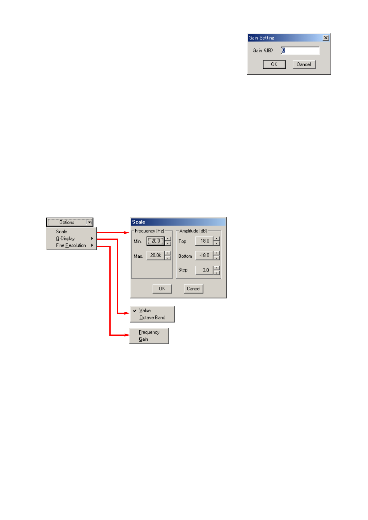
(11) Option button
Pressing this button causes the following pull-down menu to appear:
Scale... : Changes the scale.
Q-Display: The method to display Q can be changed by selecting "Value" or "Octave Band." (Only
valid for parametric equalizers.)
High Resolution: You can change the frequency step width if "Frequency" is selected, and the gain width
if "Gain" is selected.
Page 23
23
8.4. Comp/Leveler View (Compression/Auto-leveler Function Settings)
The Comp/Leveler view is displayed if you click the Comp box (when selecting Compressor mode*) or Leveler
box (when selecting Auto-Leveler mode*).
* Selection of each mode for input channel can be performed in the Comp/Leveler view.
Only the compression function is provided for output channel, while the auto-leveler function is not provided.
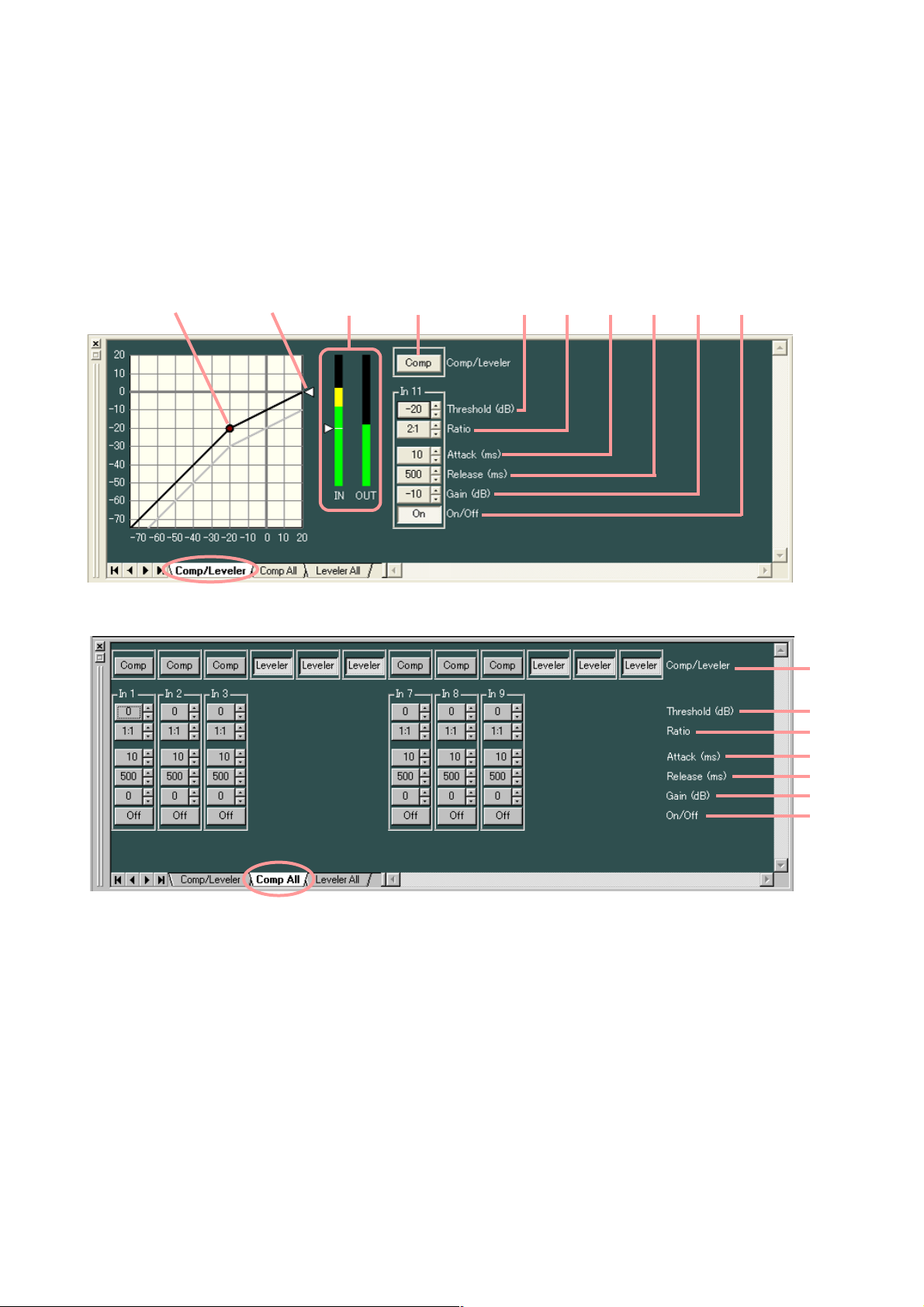
8.4.1. Compression function settings
The setting screens used here are examples for the input channel.
In output channel, there are no indications/settings related to the Auto-Leveler function.
(1)(2)
(3) (5) (6) (7) (8) (9) (10)
Clicking the [Comp All] tab causes the setting screen for all channels set to compressor mode to appear.
(1) Mode selection button [Comp/Leveler] (Available only to input channel)
Displays the Compressor/Auto-Leveler mode. Mode selection can be performed for individual channels.
All input channels are set to compressor mode by default. Press this button to select the auto-leveler
mode, and press it again to select the compressor mode.
Note
At the time of mode selection, each parameter of compression and auto-leveler functions for the channel
returns to the initial value.
(2) Comp threshold handle
Click and drag this handle up and down to change the compression threshold level.
(3) Ratio handle
Click and drag this handle up and down to change the compression ratio.
(4)
(1)
(5)
(6)
(7)
(8)
(9)
(10)
Page 24
24
(5) Comp threshold button [Compressor Threshold (dB)]
Displays the compression threshold level for each channel by means of
numerical values. If you press this button, a dialog for threshold level
setting is displayed, enabling you to set the level by directly entering a
numerical value. (Setting range: –10 to +20 dB)
The Up and Down buttons located on the right side can also be used to
change the threshold level in 1 dB units.
(6) Comp ratio button [Compressor Ratio]
Displays the compression level for each channel by means of numerical values. If this button is pressed,
setting values can be selected from the pull-down menu. The Up and Down buttons located on the right
side can also be used to change the value.
(7) Comp attack button [Compressor Attack (ms)]
Displays the compression attack time for each channel by means of numerical values. Pressing this button
permits setting values to be selected from the pull-down menu. The Up and Down buttons located on the
right side can also be used to change the value.
(8) Comp release button [Compressor Release (ms)]
Displays the compression release time for each channel by means of numerical values. Pressing button
permits setting values to be selected from the pull-down menu. The Up and Down buttons located on the
right side can also be used to change the value.
(9) Comp gain button [Gain (dB)]
Displays the compression gain for each channel by means of numerical
values. If you press this button, a dialog for compression gain settings
is displayed, enabling you to set the gain by directly entering a
numerical value.
Setting range: –∞ (–70) to +10 dB
You can also change the gain in 1 dB units with the Up and Down
buttons located on the right side.
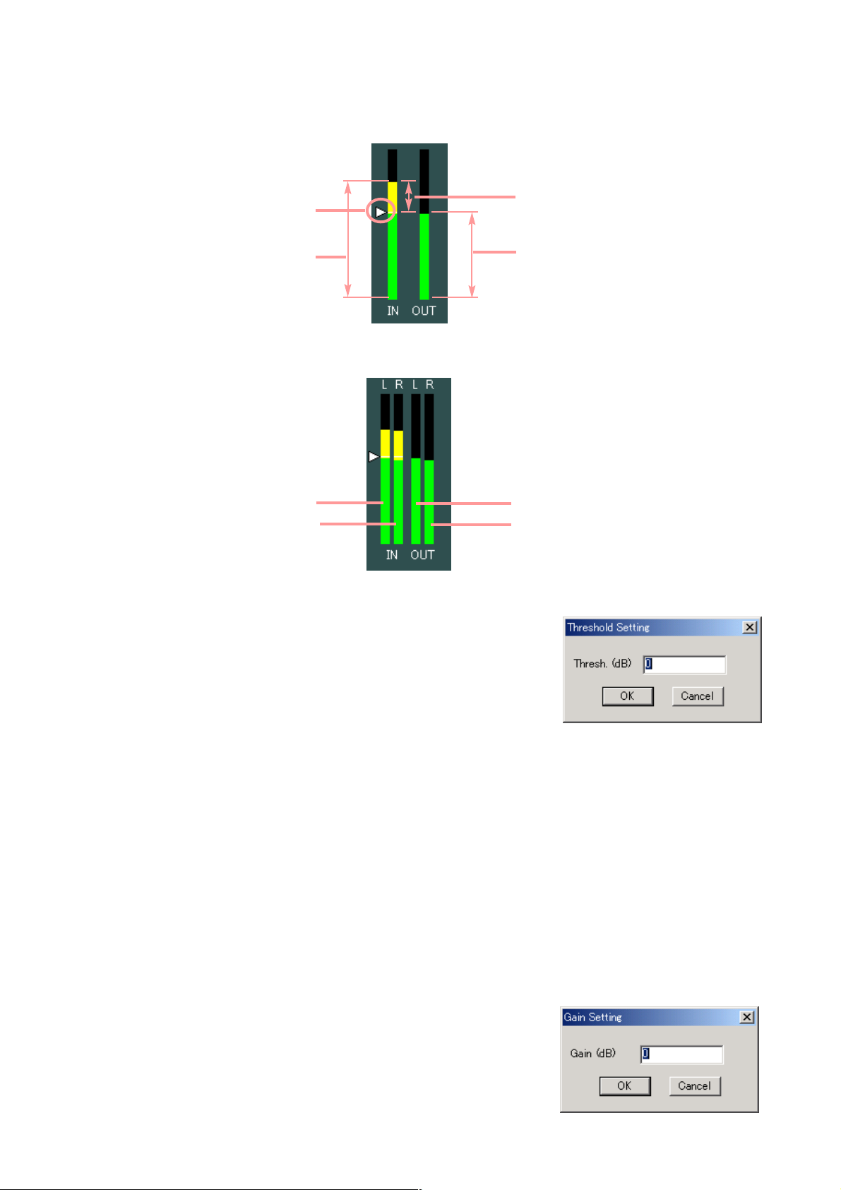
Threshold level
Input signal level
Reduction level
Output signal level
L channel input level meter
R channel input level meter
L channel output level meter
R channel output level meter
(4) Input/output level meter
Displays the input/output signal, the reduction (how much the compressor has worked) and the threshold
levels by way of the following bar graph when the D-901 is operating during communications between the
D-901 and the PC.
If Stereo Link function is set to channels, the level meters of both left and right channels are
simultaneously displayed.
Page 25
25
(10) Comp ON/OFF button
Displays the ON/OFF setting status of the compressor in each channel. Press this button to turn on or off
each compressor.
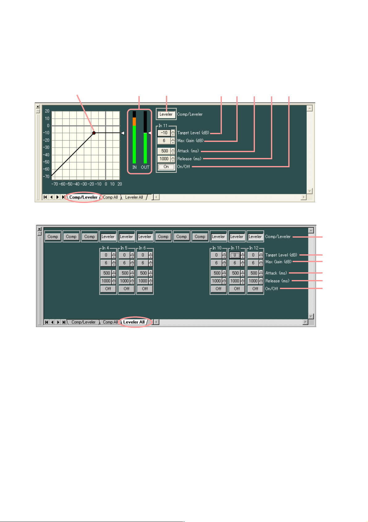
8.4.2. Auto-leveler function settings (available only to the input channel)
(1)(2)
(4) (5) (6) (7) (8)(3)
(1)
(4)
(5)
(6)
(7)
(8)
Clicking the [Leveler All] tab causes the setting screen for all channels set to auto-leveler mode to appear.
(1) Mode selection button [Comp/Leveler]
Displays the compressor/auto-leveler mode. Mode selection can be performed for individual channels.
All input channels are set to compressor mode by default. Press this button to select the auto-leveler
mode, and press it again to select the compressor mode.
Note
At the time of mode selection, each parameter of compressor and auto-leveler functions returns to the
initial value.
(2) Auto-leveler target level handle
Click and drag this handle up and down to change the auto-leveler target level.
Page 26
26
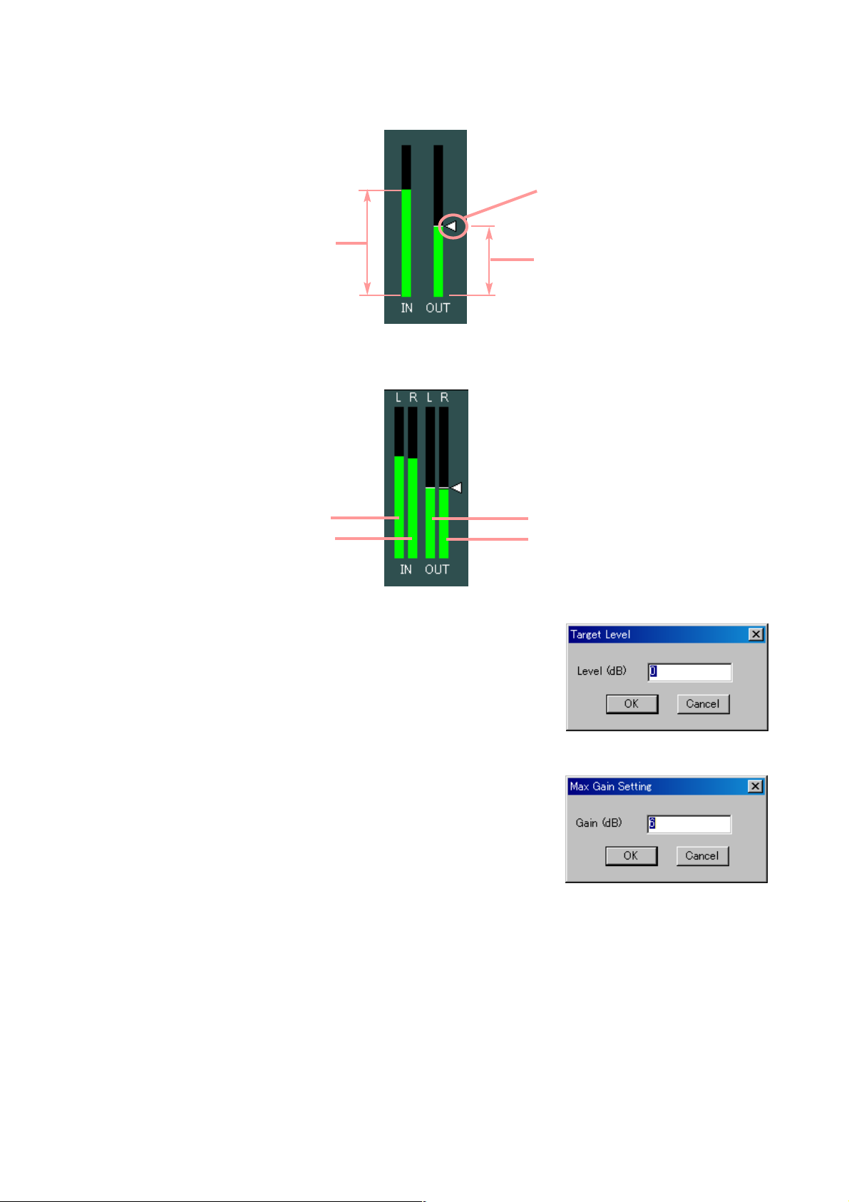
Input signal level
Target level
Output signal level
L channel input level meter
R channel input level meter
L channel output level meter
R channel output level meter
(4) Auto-leveler target level button [Target Level (dB)]
Displays the auto-leveler's threshold level for each channel by means
of numerical values.
If you press this button, a dialog for threshold level setting is displayed,
enabling you to set the level by directly entering a numerical value.
Setting Range: 20 to +20 dB
You can also change the level in 1 dB units with the UP and Down
buttons located on the right side.
(5) Auto-leveler max gain button [Max Gain (dB)]
Displays the auto-leveler max gain for each channel by means of
numerical values.
If you press this button, a dialog for max gain setting is displayed,
enabling you to set the level by directly entering a numerical value.
Setting Range: 0 to +20 dB
You can also change the level in 1 dB units with the UP and Down
buttons located on the right side.
(6) Auto-leveler attack button [Attack (ms)]
Displays the auto-leveler attack time for each channel by means of numerical values.
Pressing this button permits setting values to be selected from the pull-down menu.
The Up and Down buttons located on the right side can also be used to change the value.
(7) Auto-leveler release button [Release (ms)]
Displays the auto-leveler release time for each channel by means of numerical values.
Pressing this button permits setting values to be selected from the pull-down menu.
The Up and Down buttons located on the right side can also be used to change the value.
(8) Auto-leveler ON/OFF button [On/Off]
Displays the ON/OFF setting status of the auto-leveler in each channel.
Press this button to turn on or off each auto-leveler.
If Stereo Link function is set to channels, the level meters of both left and right channels are
simultaneously displayed.
(3) Input/Output level meter
Displays the input/output signal and the target levels by way of the following bar graph when the D-901 is
operating during communications between the D-901 and the PC.
Page 27

27
8.5. Automix View (Auto-mixing Function Settings)
Clicking the Automix box of Auto-mixing Function causes the Automix View to appear.
8.5.1. Gate function settings
If you click the box of Auto-mixing Function, the screen of the [GATE] tab is first displayed.
Click the [Gate All] tab. The setting screen for all channels is then displayed.
(2) (4) (5) (6) (7) (8) (9) (10) (11) (12) (13)
(1) Auto-mixing group setting button [Automix Group]
Sets the auto-mixing group assignment to each channel.
Pressing this button permits groups to be selected from the pull-down menu.
This setting can also be performed on the screen displayed by clicking [NOM] or [Ducker] tabs.
(2) Gate threshold handle
Click and drag this handle left and right to change the gate threshold level.
(1)
(3)
(1)
(4)
(5)
(6)
(7)
(8)
(9)
(10)
(11)
(12)
(13)
Page 28

28
(4) Level attack button [Level Attack (ms)]
Displays the level sensing attack time for each channel by means of numerical values. Pressing this button
permits setting values to be selected from the pull-down menu. The Up and Down buttons located on the
right side can also be used to change the value.
(5) Level release button [Level Release (ms)]
Displays the level sensing release time for each channel by means of numerical values. Pressing this
button permits setting values to be selected from the pull-down menu. The Up and Down buttons located
on the right side can also be used to change the value.
(3) Input/Output level meter
Displays the input/output signal and the threshold levels by way of the following bar graph when the D-901
is operating during communications between the D-901 and the PC.
Input signal level
Output signal level
Threshold level
Open threshold level
Close threshold level
L channel input level meter
R channel input level meter
L channel output level meter
R channel output level meter
If the hysteresis is set, both open and close threshold levels are displayed.
If Stereo Link function is set for channels, the level meters of both left and right channels are
simultaneously displayed.
Page 29

29
(6) Gate threshold button [Gate Threshold (dB)]
Displays the gate threshold level for each channel by means of
numerical values. If you press this button, a dialog for threshold
level setting is displayed, enabling you to set the level by directly
entering a numerical value. (Setting range: –50 to +20 dB.) You can
also change the threshold level in 1 dB units with the Up and Down
buttons located on the right side.
(7) Gate hysteresis button [Gate Hysteresis (dB)]
Displays the gate hysteresis for each channel by means of
numerical values. If you press this button, a dialog for hysteresis
setting is displayed, enabling you to set the hysteresis by directly
entering a numerical value.
Setting range: –∞ (–70) to +10 dB
You can also change the hysteresis in 1 dB units with the Up and
Down buttons located on the right side.
(8) Gate depth button [Gate Depth (dB)]
Displays the gate depth for each channel by means of numerical
values. If you press this button, a dialog for depth setting is
displayed, enabling you to set the depth by directly entering a
numerical value.
Setting range: –∞ (–70) to 0 dB
You can also change the depth in 1 dB units with the Up and Down
buttons located on the right side.
(9) Gate hold button [Gate Hold (ms)]
Displays the gate holding time for each channel by means of numerical values. Pressing this button
permits setting values to be selected from the pull-down menu. The Up and Down buttons located on the
right side can also be used to change the value.
(10) Gate attack button [Gate Attack (ms)]
Displays the gate attack time for each channel by means of numerical values. Pressing this button
permits setting values to be selected from the pull-down menu. The Up and Down buttons located on the
right side can also be used to change the value.
(11) Gate release button [Gate Release (ms)]
Displays the gate release time for each channel by means of numerical values. Pressing this button
permits setting values to be selected from the pull-down menu. The Up and Down buttons located on the
right side can also be used to change the value.
(12) Gate ON/OFF button [Gate On/Off]
Displays the ON/OFF setting status of the gate function for each channel. Press this button to determine
whether (ON) or not (OFF) to use the gate function.
(13) Gate status indicator [Gate Close]
Lights blue when the gate operates (closes).
Page 30

30
8.5.2. NOM attenuation function settings
Click the [NOM] tab. The NOM attenuation function setting screen for all channels is then displayed.
(1)
(2)
(1) Auto-mixing group setting button [Automix Group]
Sets the auto-mixing group assignment to each channel.
Pressing this button permits groups to be selected from the pull-down menu.
This setting can also be performed on the screen displayed by clicking [GATE], [Gate All] or [Ducker]
tabs.
(2) NOM attenuation ON/OFF button [NOM On/Off]
Displays the ON/OFF setting status of the NOM attenuation function for each channel. Press this
button to determine whether (ON) or not (OFF) to use the NOM attenuation function.
(3) NOM attenuation button [NOM Attenuation]
Displays the NOM attenuation gain by means of numerical values.
If you press this button, a dialog for NOM setting is displayed,
enabling you to set the NOM attenuation gain by directly entering
a numerical value.
Setting range: 0 – 20 (0 log
10NOM – 20 log10NOM)
The Up and Down buttons located on the right side can also be
used to change the value.
Page 31

31
8.5.3. Ducker function settings
Click the [Ducker] tab. The Ducker setting screen for all channels is then displayed.
(3)
(4)
(5)
(2)
(1)
(1) Auto-mixing group setting button [Automix Group]
Sets the auto-mixing group assignment to each channel.
Pressing this button permits groups to be selected from the pull-down menu.
This setting can also be performed on the screen displayed by clicking [GATE], [Gate All] or [NOM] tabs.
(2) Priority button [Ducker Priority Level]
Displays priorities for each channel. (1 – 8; 1: Highest, 8: Lowest)
A dialog for setting priorities is displayed if you press this button,
enabling you to perform the setting by directly entering a numerical
value.
The Up and Down buttons located on the right side can also be used
to change the value.
(3) Ducker depth button [Ducker Depth (dB)]
Displays the Ducker depth for each channel by means of numerical
values. A dialog for setting the depth is displayed if you press this
button, enabling you to perform the setting by directly entering a
numerical value.
Setting range: –∞ (–70) to 0 dB
The Up and Down buttons located on the right side can also be used
to change the value.
(4) Ducker attack button [Ducker Attack (ms)]
Displays the Ducker attack time for each channel by means of numerical values. Pressing this button
permits setting values to be selected from the pull-down menu. The Up and Down buttons located on the
right side can also be used to change the value.
(5) Ducker release button [Ducker Release (ms)]
Displays the Ducker release time for each channel by means of numerical values. Pressing this button
permits setting values to be selected from the pull-down menu. The Up and Down buttons located on the
right side can also be used to change the value.
(6) Ducker ON/OFF button [Ducker On/Off]
Displays the ON/OFF setting status of the Ducker function for each channel. Press this button to determine
whether (ON) or not (OFF) to use the Ducker function.
(6)
Page 32

32
8.6. Fader View (I/O Gain and I/O Group Trim Settings)
Clicking the Fader box causes the Fader View to appear.
8.6.1. I/O gain settings
The screen of the [Fader] tab is first displayed if you click the Fader box.
(3)
(4)
(5)
(2)
(1)
(1) Grouping button [Grouping]
Displays the channel group number assigned to each channel.
Press this button and select [Grouping → (Channel)] to perform the channel group setting.
If you move a fader of a grouped channel, the faders of other channels of the same group also move in
synchronization with the first operated fader.
The channel group setting makes the group trim gain (Gr. Trim) valid, allowing the offset gain of each
grouped channel to be set.
(2) Group trim gain button [Gr Trim]
Displays the group trim gain set for each channel by means of
numerical values.
When channel group settings have been performed, if you press
this button, a dialog for fader setting displayed, enabling you to set
the trim gain by directly entering a numerical value. The group trim
gain setting performed in this dialog corresponds directly to the
group trim gain setting shown on the [Gr Trim] tab screen.
Setting range: –∞ (–80) to +10 dB
The Up and Down buttons located on the right side can also be
used to change the value in 0.1 dB units.
(3) Fader
Used to change the signal level of each channel.
(4) Gain indication button [Fader (dB)]
Displays the level for each channel by means of numerical values.
A dialog for fader setting is displayed if you press this button,
enabling you to perform the setting by directly entering a numerical
value.
Setting range: –∞ (–70) to 0 dB
The Up and Down buttons located on the right side can also be
used to change the value in 0.1 dB units.
(5) Channel ON/OFF button [On/Off]
Displays the ON/OFF setting status of each channel. Press this button to turn on or off the channel.
Page 33

33
8.6.2. I/O group trim settings
Click the [Gr Trim] tab. The setting screen for the trim gain by means of fader operations is then displayed.
(1)
(2)
(1) Fader
If the channel group setting has been performed, the group trim gain for each channel can be changed
by moving the fader up and down.
(2) Group trim gain button [Gr Trim]
Displays the group trim gain set for each channel by means of
numerical values.
When channel group settings have been performed, if you press this
button, a dialog for gain setting is displayed, enabling you to set the
gain by directly entering a numerical value.
The group trim gain setting performed in this dialog corresponds
directly to the group trim gain setting shown on the [Fader] tab
screen.
Setting range: –∞ (–70) to +10 dB
Page 34

34
8.7. Filter View (Filter Function Settings)
Click the Filter box of Multi-band Filter. The Filter View is then displayed.
(1) (2)
(3)
(4)
(5)
(6)
(7)
(8)
(9)
(10)
(Displayed in tabular form)
(3)
(4)
(5)
(6)
(7)
(8)
(9)
(10)
(1)
(1) Filter control
(2) Filter point symbol
Select the filter point from the filter point symbol as required. If you right-click a point
on the filter point symbol, the popup menu shown at right is displayed.
Clicking any option other than "Through" causes a circle to appear on the filter
control section. To cancel it, right-click the filter point symbol again and select
"Through." The circle on the filter control section disappears. A yellow circle
indicates the selected filter point.
: Parametric equalizer (PEQ)
: High-pass filter (HPF)
: Low-pass filter (LPF)
: High shelving filter (High Shelving)
: Low shelving filter (Low Shelving)
: Horn equalizer (Horn EQ)
: Notch filter (Notch)
: All-pass filter (All Pass)
You can change the frequency and the gain if you drag the filter point on the filter control. When a white
circle is displayed on the left side of the filter point, by clicking and dragging the white circle up and down,
the Q value of the selected filter point can be changed.
(3) Filter type indication button
Indicates the type of filter of the selected filter point.
Press this button to select the type of filter from the pull-down menu.
Selecting "Through" causes the circle to disappear from the filter control section.
Page 35

35
(4) Frequency indication button [Freq. (Hz)]
Displays the frequency of the selected filter point.
If you press this button, a dialog for frequency setting is displayed,
enabling you to set the frequency by directly entering a numerical
value. (Setting range: 20 – 20,000 Hz)
The setting can also be changed in 1/24 octave units (this step
width can be changed with the Option button) with the use of the
Up and Down buttons located on the right side.
(5) Gain indication button [Gain (dB)]
Displays the gain of the selected filter point.
If you press this button, a dialog for gain setting is displayed,
enabling you to set the gain by directly entering a numerical value.
(Setting range: –15 to +15 dB)
The setting can also be changed in 0.5 dB units (in 0.1 dB units
using the Option button) with the use of the Up and Down buttons
located on the right side.
(6) Q indication button [Q]
Displays the Q value of the selected filter point.
Pressing this button permits the setting value to be selected from the pull-down menu.
(7) Table indication button
The filter control is displayed in tabular form if this button is pressed. To return the screen to the original
graphical display, press this button again.
(8) Filter ON/OFF button
Displays the ON/OFF setting status of the selected filter.
Press this button to determine whether (ON) or not (OFF) to use the filter.
(9) Frequency response indication button
Used to show or hide the Response View (see p. 47).
(10) Option button
The following pull-down menu is displayed if you press this button.
Scale... : Scale can be changed.
Q-Display: The method to indicate the Q value can be changed by selecting "Value" or "Octave
Band." (Only available when the parametric equalizer, notch filter or all-pass filter is
selected.)
Fine Resolution: Selection of "Frequency" permits the frequency step width to be changed. If "Gain" is
selected, the gain step width can be changed.
Page 36

36
8.8. Xover View (Crossover Function Settings)
The Xover View is displayed if the , , or button of Xover is clicked.
8.8.1. Crossover function settings
The screen of the [Xover] tab is first displayed if the box of Xover is clicked.
(1)
(2)
(3)
(4)
(8)
(9)
(10)
The indication displayed at the upper right of the screen changes depending on the type of selected filter.
[When "12 dB Variable-Q" or "18 dB Variable-Q" is selected]
(3)
(4)
(5)
(3)
(4)
(5)
(5)
(3)
(4)
(6)
(7)
[When "24 dB Variable-Q" is selected]
[When other filter type than those stated above is selected]
[When "Gain" is selected]
(5)
Page 37

37
(Displayed in tabular form)
(3)
(4)
(8)
(9)
(10)
(1)
(1) Filter control
(2) Filter point
A circle on the filter control indicates the operable filter point. A yellow circle indicates the selected filter
point.
When selected/ When not selected: High-pass filter
When selected/ When not selected: Low-pass filter
When selected/ When not selected: Gain control
You can change the cut-off frequency of the selected filter point if you click and drag the low-pass or highpass filter left and right.
To change the gain of the selected filter point, click and drag the gain control point up and down.
When a white circle is displayed on the right or left side of the filter point, if the white circle is clicked and
dragged up and down, the Q value of the selected filter point can be changed.
(3) Filter type indication button
Displays the type of filter of the selected filter point.
Pressing this button permits the filter type to be selected from the pull-down menu.
(4) Frequency indication button [Freq. (Hz)]
Displays the frequency of the selected filter point.
If you press this button, a dialog for frequency setting is displayed,
enabling you to set the frequency by directly entering a numerical
value.
Setting range: 20 – 20,000 Hz
The button located on the right side can also be used to change the
frequency setting.
(5) Q/Q2 indication button [Q, Q2]
Displays the Q value of the selected filter point.
Pressing this button permits a setting value to be selected from the pull-down menu.
(6) Gain indication button [Gain (dB)]
Displays the gain of the selected gain control point.
If you press this button, a dialog for gain setting is displayed,
enabling you to set the gain by directly entering a numerical value.
Setting range: –15 to +15 dB
The button located on the right side can also be used to change the
value in 0.1 dB units.
(7) Reverse polarity button [Polarity]
Displays the polarity of the selected filter point.
Press this button to reverse the polarity.
(5)
Page 38

38
(8) Table indication button
The filter control is displayed in tabular form if this button is pressed. To return the screen to the original
graphical display, press this button again.
(9) Frequency response indication button
Used to show or hide the Response View (see p. 47).
(10) Scale change button
If you press this button, a dialog for scale setting is displayed,
enabling you to change the graph scale of the filter control.
Page 39

39
8.8.2. Time correction settings between Xover boxes
If you click the [Driver Alignment] tab, the setting screen for time correction between Xover boxes is displayed.
(1) (2)
(3)
(4)
(5)
(6)
(1) Minimum variation unit selection button (Increments)
Selects the minimum units of the delay time that can be changed with the Up and Down buttons.
(2) Option button
If you press this button, a delay option dialog is displayed and you
can select the unit of distance displayed on the delay distance
indication button from meters, inches and feet.
You can also set the temperature displayed on the delay distance
indication button for distance calculation.
(3) Delay time indication button [Time (ms)]
Displays the delay time in each channel by means of a numerical
value. If you press this button, a dialog for delay time setting is
displayed, enabling you to set the delay time by directly entering a
numerical value.
(4) Delay distance indication button [Distance (meters/inches/feet)]
Displays the delay distance in each channel by means of a
numerical value. If you press this button, a dialog for delay
distance setting is displayed, enabling you to set the delay
distance by directly entering a numerical value.
(5) Up/Down button
Changes the delay time in minimum variation units.
(6) Delay ON/OFF button [On/Off]
Displays the ON/OFF setting status of the delay function.
Press this button to enable or disable the delay function.
Page 40

40
8.9. Delay View (Delay Function Settings)
If you click the Delay box, the Delay View is displayed.
(1) (2)
(3)
(4)
(5)
(6)
(1) Minimum variation unit selection button (Increments)
Selects the minimum units of the delay time that can be changed with the Up and Down buttons.
(2) Option button
If you press this button, a delay option dialog is displayed and you
can select the unit of distance displayed on the delay distance
indication button from meters, inches and feet.
You can also set the temperature displayed on the delay distance
indication button for distance calculation.
(3) Delay time indication button [Time (ms)]
Displays the delay time in each channel by means of a numerical
value. If you press this button, a dialog for delay time setting is
displayed, enabling you to set the delay time by directly entering a
numerical value.
(4) Delay distance indication button [Distance (meters/inches/feet)]
Displays the delay distance in each channel by means of a
numerical value. If you press this button, a dialog for delay
distance setting is displayed, enabling you to set the delay
distance by directly entering a numerical value.
(5) Up/Down button
Changes the delay time in minimum variation units.
(6) Delay ON/OFF button [On/Off]
Displays the ON/OFF setting status of the delay function.
Press this button to enable or disable the delay function.
Page 41

41
8.10. Effect/Echo View (Effect/Echo Function Settings)
If you click the Effect (Echo) box, the Effect/Echo View is displayed.
(1)
(2)
(3)
(4)
(5)
(6)
(7)
(1) Gain indication button [Output Gain (dB)]
Displays the echo output gain. A dialog for gain setting is displayed if
you press this button, enabling you to set the gain by directly entering a
numerical value.
Setting range: –∞ (–70) to 0 dB
The Up and Down buttons located on the right side can also be used to
change the value in 1 dB units.
(2) Ratio indication button [Feedback Ratio (%)]
Displays the feedback ratio. A dialog for ratio setting is displayed if you
press this button, enabling you to set the ratio by directly entering a
numerical value.
Setting range: 0 – 99%
The Up and Down buttons located on the right side can also be used to
change the value in 1% units.
(3) Feedback delay button [Feedback Delay (ms)]
Displays the feedback delay time. A feedback delay time setting dialog
is displayed if you press this button, enabling you to set the delay time
by directly entering a numerical value.
Setting range: 0 – 682 ms
The Up and Down buttons located on the right side can also be used to
change the value in 1 ms units.
(4) Pre-delay button [Pre-Delay (ms)]
Displays the pre-delay time. A pre-delay time setting dialog is displayed
if you press this button, enabling you to set the pre-delay time by
directly entering a numerical value.
Setting range: 0 – 682 ms
The Up and Down buttons located on the right side can also be used to
change the value in 1 ms units.
(5) Low-pass filter frequency button [LPF Freq. (Hz)]
Displays the low-pass filter's cut-off frequency. A dialog for cut-off
frequency setting is displayed if you press this button, enabling you to
set the frequency by directly entering a numerical value.
Setting range: 20 – 20,000 Hz
The Up and Down buttons located on the right side can also be used to
change the value.
(6) Q indication button [LPF Q]
Displays the low-pass filter's Q value. Pressing this button permits the setting value to be selected from the
pull-down menu.
The Up and Down buttons located on the right side can also be used to change the value.
Page 42
42
(7) Echo ON/OFF button [On/Off]
Displays the ON/OFF setting status of the echo function.
Press this button to enable or disable the echo function.
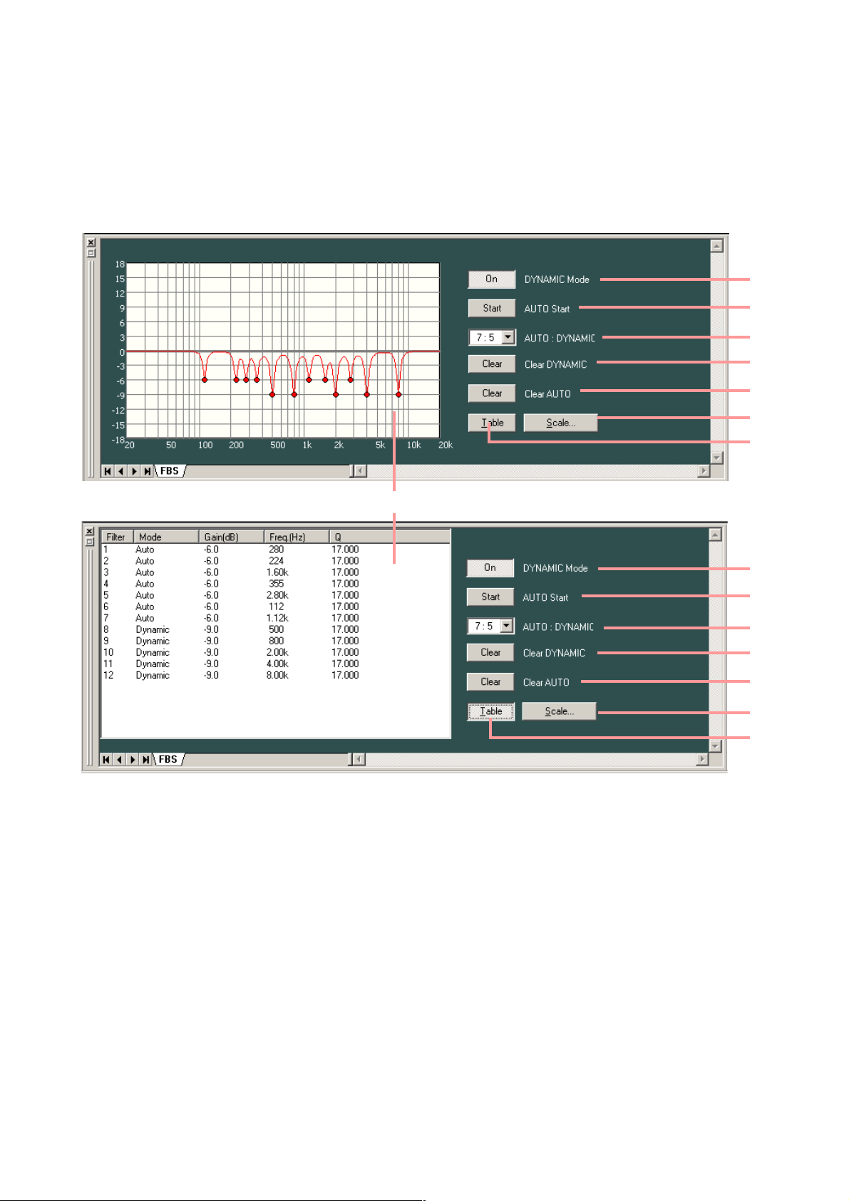
8.11. FBS View (Feedback Suppression Function Settings)
Clicking the FBS box of the feedback suppression function causes the FBS View to be displayed.
(Displayed in tabular form)
(1)
(2)
(3)
(4)
(5)
(6)
(7)
(1)
(2)
(3)
(4)
(5)
(6)
(7)
(8)
(1) Dynamic mode button [DYNAMIC Mode]
Displays the ON/OFF setting status of the dynamic mode.
Press this button to set the mode to ON or OFF.
(2) Auto start button [AUTO Start]
Auto mode is activated if this button is pressed while a connection is being established between the D-901
unit and a PC for communications.
(3) Filter number indication button [AUTO: DYNAMIC]
Displays the number of filters for auto mode and dynamic mode. You can select the number of filters from
the pull-down menu if you press this button.
(4) Clear dynamic button [Clear DYNAMIC]
Clears the setting of the dynamic mode filter and returns it to the initial status.
(5) Clear auto button [Clear AUTO]
Clears the setting of the auto mode filter and returns it to the initial status.
Page 43

43
(6) Scale change button
If you press this button, a dialog is displayed, enabling you to
change the scale of the characteristics graphic chart.
(7) Table indication button
Displays the filter status display area in tabular form.
(8) Filter status indication area
Displays the responses of the current dynamic mode filters and auto mode filters. Each filter's setting value
is displayed in tabular form.
8.12. Microphone/Line Input Module View
(Available only when the D-921E or D-921F is used)
Click the "D-921" box displayed on the input slot in the Flow View. The Microphone/Line Input Module View is
then displayed.
(1)
(2)
(1) Phantom power ON/OFF button [Phantom Power]
Displays the ON/OFF setting status of the selected channel.
Press this button to turn on or off the phantom power. (Always set to OFF when LINE is selected with the
PAD button.)
(2) PAD button [PAD]
Displays the PAD settings of the selected channel. You can select the setting value from the pull-down
menu if you press this button.
Page 44

44
8.13. Digital Input Module View (Available only when the D-923AE is used)
Click the "D-923AE" box displayed on the input slot in the Flow View. The Digital Input Module View is then
displayed.
(1)
(2)
(3)
(1) Channel status indication [Status]
Displays the input signal status of the selected channel.
Display Input signal status
LOCK Normal
UNLOCK No cable connected or equipment power not
turned on
Non AUDIO Not an audio signal
Non PCM Not PCM data
DTS CD DTS CD
The indications are shown by black text on white background for the LOCK status, and white text on red
background for the error status.
In error status, the error status indicator lights red on the "D-923AE" box in the Flow View as shown below.
(2) Sampling frequency indication [Fs (Hz)]
Displays the sampling frequency of the selected channel.
(3) Pre-emphasis ON/OFF status [Pre Emphasis]
Displays the pre-emphasis ON/OFF status of the selected channel.
Page 45

45
8.14. Stereo Input Module View (Available only when the D-936R is used)
Click the "D-936R" box displayed on the input slot in the Flow View. The Stereo Input Module View is then
displayed.
(1)
(2)
(1) Mode indication button
Displays the operation mode of the module. You can select the mode from the pull-down menu if you
press this button.
(2) ON/OFF control [1, 2, 3, 4]
• Displays the ON/OFF setting status of the module's inputs 1 – 4. The input indicated by the symbol is
set to ON.
• The input toggles between "ON" and "OFF" each time it is double-clicked.
• The thick, black frame on the ON/OFF control indicates the selected input.
• Each of Inputs 1 – 4 can be individually set to ON or OFF when in MIX ALL mode.
• Any one of inputs 1 – 4 can be set for ON when in SELECT mode.
• Only input 1 is set to ON if mode is switched from MIX ALL to SELECT mode.
• All inputs 1 – 4 are set to ON if mode is switched from SELECT to MIX ALL mode.
Page 46

46
8.15. Digital Input Module View (Available only when the D-937SP is used)
Click the "D-937SP" box displayed on the input slot in the Flow View. The Digital Input Module View is then
displayed.
(1)
(2)
(3)
(4)
(1) Channel status indication [Status]
Displays the input signal status of the selected channel.
Display Input signal status
LOCK Normal.
UNLOCK No cable connected or equipment power not
turned on.
Non AUDIO Not an audio signal.
Non PCM Not PCM data.
DTS CD DTS CD.
The indications are shown by black text on white background for the LOCK status, and white text on red
background for the error status.
In error status, the error status indicator lights red on the "D-937SP" box in the Flow View as shown below.
(2) Sampling frequency indication [Fs (Hz)]
Displays the sampling frequency of the selected channel.
(3) Pre-emphasis ON/OFF status [Pre emphasis]
Displays the pre-emphasis ON/OFF status of the selected channel.
(4) D-937SP module input selection (Line selection) [1, 2, 3, 4]
Displays the selected status of the D-937SP module's inputs 1 – 4. The selected input is indicated by the
symbol. Double-clicking the input indication switches the selection status between "selected" and
"unselected."
Note
Unlike the MIX ALL mode of the D-936R, only one input can be selected.
Page 47

47
9. RESPONSE VIEW
Select [View → Response View] from the menu or press the Frequency response indication button on the
HPF/PEQ, Filter or Xover View to show or hide the Response View. The Response View can display the
output response and Xover response.
9.1. Output Response View
• Displays an overall response from input to output.
• Permits selection of Inputs routed by matrix for each output channel.
• Permits display of 3 types of responses: amplitude, phase and group delay responses.
(1) (2) (3) (4) (5)
(1) Response indication selection button
Displays the types of frequency responses being currently displayed. If this button is pressed, the type of
frequency response to be displayed can be selected from the pull-down menu. There are a full-screen
display that displays any one of amplitude, phase and group delay responses, and a dual-split screen
display that displays two of these 3 responses.
(2) Scale change button
Press this button. A dialog for scale setting is then displayed and
the graph scale of the response control can be changed.
(3) Response indication area
(4) Input selection button [Output 1 – 8]
Press this button to determine whether or not to display the response of each output channel and select
input channels from the pull-down menu.
Page 48

48
(5) Color change button
If this button is pressed, a dialog for color setting is displayed,
permitting the display colors of response curves of each channel to
be changed.
9.2. Xover Response View
• Displays crossover and filter response curves.
• Displays each channel response, as well as their added overall response.
• Displays the amplitude response, phase response, and group delay response.
(1) (2) (3) (4) (5) (6) (7) (8)
(9)
(1) Response indication selection button
Displays the types of frequency responses being currently displayed. If this button is pressed, the type of
frequency characteristic to be displayed can be selected from the pull-down menu. There are a full-screen
display that displays any one of amplitude, phase and group delay responses, and a dual-split screen
display that displays two of these 3 characteristics.
(2) Scale change button
Press this button. A dialog for scale setting is then displayed and
the graph scale of the response control can be changed.
Page 49

49
(3) Measuring data import button
You can simulate crossover settings of the multi-way speaker by importing measuring data.
Press this button to select the channel from the pull-down menu.
(4) Measuring data calibration button
Press this button to display a dialog for response display calibration.
Change "Amplitude" to calibrate the amplitude response, and
"Receive Delay" to calibrate the phase response.
(5) Response display area
(6) Response display button
Press this button to select whether or not to display each channel's response.
(7) On/Off button
Press this button to select whether or not to add each channel's response to an overall response.
(8) Color change button
If this button is pressed, a dialog for setting the color is displayed,
allowing the display color of each channel's response curve to be
changed.
(9) Characteristic display button
Press this button to select whether or not to display an overall response comprised of added responses of
each channel.
Page 50

50
10. PRESET MEMORY SETTINGS
There are 16 preset memories. You can freely recall them or write data into them.
10.1. Recalling the Preset Memory
Select [Memory → Change → Memory (1 – 16)] from the menu.
It is also possible to recall from the Memory View (see p. 17).
10.2. Writing Data into the Preset Memory
Select [Memory → Store → Memory (1 – 16)] from the menu.
It is also possible to write on the Memory View (see p. 17).
Page 51

51
10.4. Changing the Name
Select [Memory → Names] from the menu. Enter a name (of up to 20 characters in length) in the memory
name setting dialog that appears after menu selection.
10.3. Preset Memory Crossfade Time Setting
Select [Memory → Crossfade Time] from the menu. The crossfade time setting dialog is displayed.
Set the crossfade time in seconds (10 s max. in 0.5 s units) when the currently selected preset memory is
switched over to a newly recalled one.
Setting the crossfade time in the All Memory box causes all preset memories (Memory 1 through 16) to be set
for the same value. When all preset memories do not have the same setting, the indication "– – – –" appears
in the All Memory box.
You can also make the above setting in the Memory View. (See p. 17.)
You can also make the above change in the Memory View. (See p. 17.)
Page 52

52
10.5. Setting the Preset Memory Recalled When Power Is Turned On
Select [Memory → Power ON → Last Memory/Memory (1 – 16)] from the menu.
Page 53

53
11. STEREO LINK SETTINGS
11.1. Stereo Link Functions
• Performing Stereo Link settings for adjoining channels (such as Channels 1 and 2, 3 and 4, and 5 and 6)
causes the compressor/auto-leveler and filter signal processing parameters to be linked. If a signal
processing parameter for either channel is modified, the corresponding parameter of the other "linked"
channel also simultaneously changes.
• The Stereo Link function can be independently set for input and output sides. Enable the Stereo Link setting
when wishing to make the settings of both left and right channels identical, such as when a joint input is
received from a CD player or other stereo sound source and joint output is sent to a tape recorder or similar
stereo equipment.
11.2. Stereo Link Settings
• Click and select the signal processing boxes of the channels you want to "link," then select [Edit → Enable
Stereo Link...]. Input and output sides can be set by clicking the signal processing box of each
corresponding side.
• Parameters of the linked channel with the lower channel number (e.g. Channel 3 when Channels 3 and 4
are stereo-linked) are copied to the channel with the higher number.
• Signal processing boxes are linked if the Stereo Link setting is made.
• "Stereo-linked" compressors/auto-levelers correspond directly to each other in operation as well.
11.3. Stereo Link Reset
To reset the Stereo Link setting, click and select any signal processing box of the desired channel, then select
[Edit → Disable Stereo Link] from the menu.
11.4. Stereo Link Setting Restrictions
• If you assign the bus from the stereo-linked input channel to the stereo-linked output channel, both left and
right channels are simultaneously assigned. For example, when Input 1 is stereo-linked to Input 2, and
Output 1 is linked to Output 2, if Input 1 is assigned to Output 1, Input 2 is also similarly assigned to Output
2. However, you cannot assign Input 1 to Output 2 or Input 2 to Output 1.
• Stereo-Link settings cannot be performed for the output channels that have employed the crossover
function. Conversely, the stereo-linked channels cannot use the crossover function.
Page 54

54
12. LEVEL MONITOR VIEW
The Level Monitor View window permits monitoring of the D-901 mixer's input and output signal levels, the
current NON/Ducker priority level, and the mixer's cooling fan operating condition while a connection is being
established between the D-901 and the PC for communications. You can show or hide the view by selecting
[View → Level Monitor View] from the menu. However, this menu selection is only valid while the D-901 and
the PC are in communication mode.
Indicates input/output signal levels as follows:
Lights red when a signal level is over 17 dB above the rated level.
Lights green when a signal level is between –40 dB above and 17 dB below the rated level.
Extinguishes when a signal level is under –40 dB below the rated level.
Lights yellow if the compressor
reduction function is enabled.
Note
If auto-leveler mode is set for
input channels, their
corresponding indicators are
not displayed.
Displays the current Ducker
priority level for each automixing group.
Lights blue while a gate is
closing.
Displays the current NOM
attenuation function status set
for each auto-mixing group.
Displays the current cooling
fan operating condition.
Page 55

55
13. COMMUNICATIONS
Set the D-901 control mode to "PC CTRL" before starting communication between the D-901 and the PC.
Note: For settings, refer to the instruction manual attached to the D-901.
• Select [Remote → Comm Setting (S)] from the menu to display the following dialog.
(1)
(3)
(4)
(5)
(6)
(2)
(1) Auto-search button
The initial setting is set to this button.
The transmission port and the transmission rate
are automatically searched when a connection is
established with the D-901
The transmission rate is automatically matched to
that set at the connected D-901.
(2) Manual button
Select this button if the Auto-search button does
not establish connections.
You can select items at (3) Port and (4) Speed
columns.
(3) Port
You can select COM Port from COM1 through
COM256.
(4) Speed
The transmission rate can be selected from
115200, 38400, 19200 and 9600 bps.
Set the transmission rate at the D-901 in
advance, and match that of the software to it.
(5) Connection timeout
Enter the time interval (0 – 60 s) up to data
retransmission.
Entering 0 (s) disables data retransmission.
(6) A default setup is changed
When setting the current communication settings
as a default value, tick the checkbox and press
[OK] button.
The current communication setting is recalled
when creating a new data.
Page 56

56
• The following dialog is displayed if the PC and the connected D-901 mixer differ in memory contents:
• Set the transfer direction to "PC>>Unit" when transferring data from the PC to the D-901, and to "Unit>>PC"
when transferring from the D-901 to the PC. You can select different transfer directions for each memory.
• After ensuring correct selection, press the [Update] button. Data transfer is started.
Note
When transferring data from the PC to the D-901, this cannot be achieved if the module configuration does
not match between the two.
• To start communications with the PC, select [Remote → Connect...] from the menu.
• Valid connections are being searched while the following dialog is displayed:
Note
The "Current Memory No." on the
screen is a memory number being
currently recalled.
Page 57

57
• Press the "Complete" button after data transfer is completed.
• To terminate communications, select [Remote → Disconnect] from the menu.
• Select [Remote → Bulk transmission] from the menu when transmitting PC data to the D-901 without
displaying the confirmation screen of the memory contents of the PC and the connected D-901 unit.
Notes
· If the module configuration does not match, data cannot be transmitted even if "Bulk transmission" is
selected.
· The optional D-984VC VCA Control Module will not control the sound volume during bulk transmission.
Decrease the sound volume before bulk transmission.
• Select [Remote → Bulk receiving] from the menu to allow the PC to receive the D-901 data without
displaying the confirmation screen of the memory contents of the PC and the connected D-901 unit. The
memory selection number recalled after bulk reception is the same as the memory number set in the D-901
(The memory number being called by the D-901).
Note
The optional D-984VC VCA Control Module will not control the sound volume during bulk receiving.
Decrease the sound volume before bulk receiving.
• To display the D-901's firmware version number, select [Remote → Firmware] from the menu during
communications. Because a dialog for D-901 version information is displayed, check it and click the [OK]
button.
Page 58

58
14. USER LEVEL
14.1. What Is the User Level?
The D-901 setting software features the following two different user levels that can be used in the Restriction
Settings explained in the next section.
• Administrator: If the user level is not set, Administrator is automatically selected for the level. Logging on as
an administrator on the logon screen also sets the user level to Administrator.
• Operator: If you do not log on as an administrator on the logon screen, the user level is set to Operator.
14.2. Enabling the User Level
Step 1. Select [Option → Security Settings...] from the menu.
A dialog for the user level and restriction settings is displayed.
Step 2. Tick the Enable User Level checkbox.
A dialog for administrator password settings is displayed.
Step 3. Enter a password (up to 16 characters in length) in the Password and Confirm Password fields, then
press the [OK] button.
Page 59

59
14.3. Logging On When the User Level Is Enabled
The following logon screen is displayed when the file is opened after the user level has been enabled:
When logging on as an administrator, enter a set password and press the [OK] button. If a different method
than this is used to close the logon screen, the user level is logged on as an operator. The level logged on is
displayed on the right side of the status bar located at the lower part of the main screen.
Page 60

60
15. RESTRICTION SETTINGS
[Operations that can be restricted]
• Crossover combination change [Crossover Combination settings]
• Stereo Link settings and Fader group settings [Stereo link settings/Fader group settings]
• NOM attenuation change [NOM attenuation settings]
• Name change [Naming]
• Storage in memory [Storing Memories]
• Each functional box's parameter change
[Performing Restriction settings]
Step 1. Select [Option → Security Settings...] from the menu.
The Security Settings dialog is displayed.
Page 61

61
For "Store to memories," different restriction settings can be assigned to each of 16 memories.
Step 2. Select the restriction level from the pull-down menu of each item of Restriction settings.
You can set 4 different levels of restrictions for each item.
Off Both administrators and operators can change the item and Restriction settings.
Low Administrators can change the item and Restriction settings.
Operators cannot change the item, but can change Restriction settings.
Mid Administrators can change the item and Restriction settings.
Operators cannot change the item and Restriction settings.
High Administrators cannot change the item, but can change Restriction settings.
Operators cannot change the item and Restriction settings.
Page 62

62
If you select "Memory" from "Storing Memories" pull-down menu, the Restriction of store dialog for
Restriction settings by memory is displayed, enabling you to set 4 different restriction levels for each
memory.
[Restricting each box's parameter change]
It is possible to set restriction of parameter change to individual
boxes displayed on the flow view.
After selecting the box on the flow view, select [Edit → Write
Protect to Box] from the menu.
You can set 4 different levels of restrictions for each item in the
same way as stated in the preceding clause. (Off, Low, Mid or
High)
Page 63
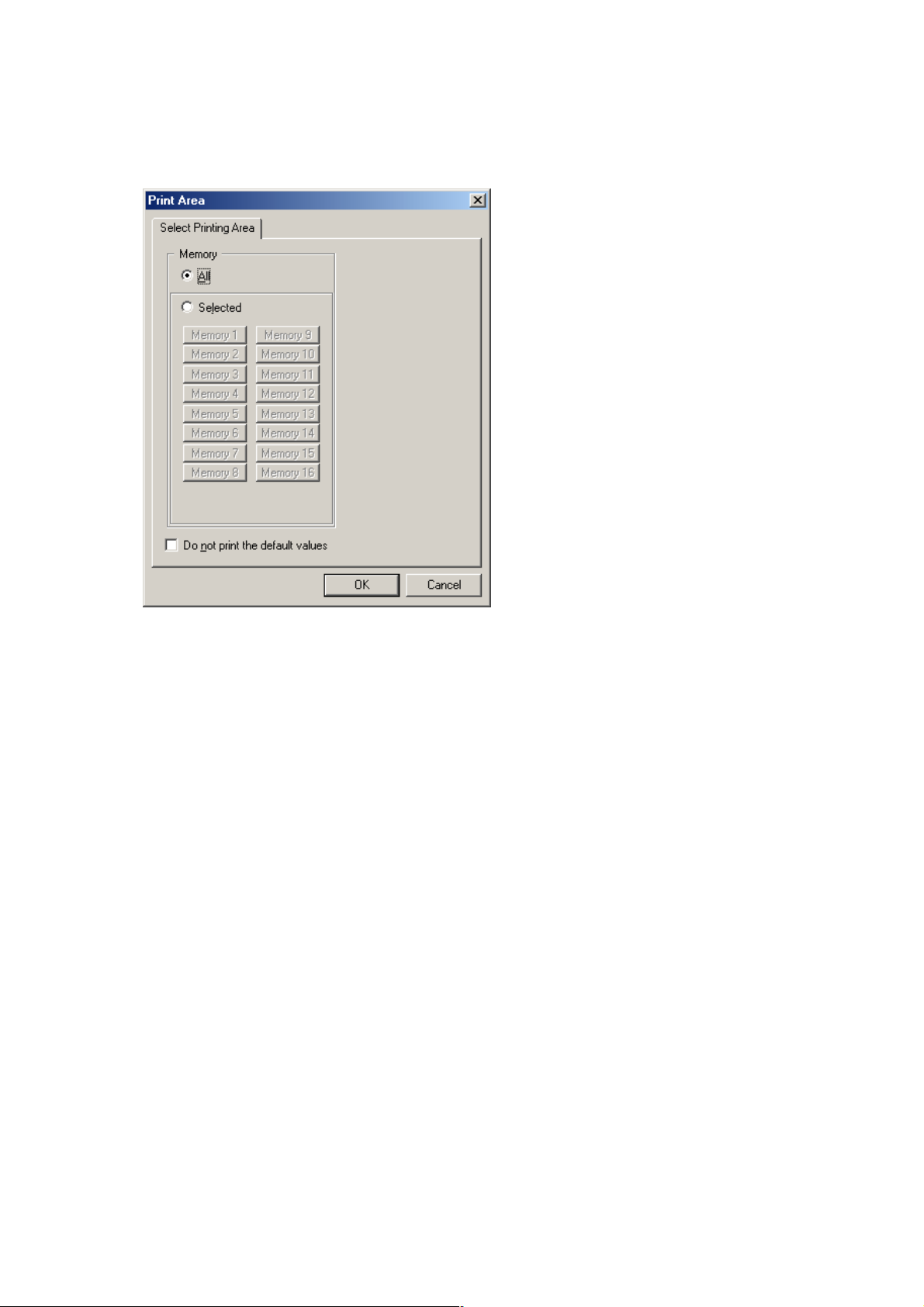
63
16. PRINT
You can print data of the file being edited.
Step 1. Select [File → Print...] from the menu.
The "Print Area" dialog is displayed.
Step 2. Select the memory you want to print.
2-1. To print the contents of all memories, select "All" in "Memory."
2-2. To print selected memories, select the option "Selected" in "Memory" and using the 16 buttons
located under it, select the memories to be printed.
Step 3. Tick the "Do not print the default values" checkbox if you do not want to print the initial values of
HPF/PEQ, Filter and Xover.
Note
This can save required printing paper and print time if the initial values do not need to be printed.
Step 4. Press the [OK] button to start printing.
Page 64

64
17. SETTINGS REQUIRED WHEN THE D-981, D-983, OR D-984VC IS USED
17.1. The Outline of the D-981, D-983, and D-984VC
Mounting the optional D-981 or D-983 Remote Control Module, or the D-984VC VCA Control Module in the D901 Mixer permits the D-901's memory selection, input/output volume control, channel ON/OFF operations,
and stereo input selection (the D-936R or D-937SP must be installed) to be remotely controlled from external
equipment. Also, status data of the D-901's memory selection, channel ON/OFF and stereo input selection
(the D-936R or D-937SP must be installed) can be transmitted to external equipment. For mounting the D981, refer to the instruction manual included with the D-901.
External remote control is performed by shorting terminals 1 – 8 (1 – 24 for the D-983) to the C terminal.
Taking the contact input setting as an example, when terminals 1 – 8 are assigned to preset memory Nos. 1 –
8 respectively by means of the memory selection function, if each terminal is shorted to the C terminal, preset
memory Nos. 1 – 8 can be recalled.
The contact input terminals 1 – 8 are preset to recall the "Preset Memory 1 – 8" when activated, the contact
output terminals 1 – 8 are preset to provide make contact when the "Preset Memory 1 – 8" is recalled, and
other input and output contacts are preset to "None" or "Normally break." By changing the settings on the
contact input and output setting screens, many different functions can be assigned to the contact input and
output.
17.2. Contact Input Setting Screen
The Contact Input setting screen is displayed if you select [Option → External Control → Contact input] from
the menu.
(1) Function
Sets the terminal function.
The terminal pins 1 – 8 are factory-preset to
"Memory 1 – 8," and other pins to "None."
• Memory
Memory selection
• Volume Up/Down
Input/output volume adjustment
• Channel On
Channel ON/OFF setting
• Line input
Stereo input selection (the D-936R or D-937SP
must be installed)
• None
No function is assigned to the terminal.
(2) Parameter
Sets the preset memory number for memory
selection, and the input number for stereo input
selection.
Page 65

65
(3) Control
The method of control given to the terminal.
You can select "Make" or "Pulse" for the control
method when the function is set to channel ON.
• Make
Channels are set to ON if each terminal is
shorted to the C terminal, and to OFF if
opened.
• Pulse
Channel settings toggle between ON and OFF
as each terminal is shorted to the C terminal.
(4) Position
Selects the input or output for the input/output
volume adjustment and channel ON/OFF
settings, and the slot in which the D-936R or D937SP is inserted for stereo input selection.
(5) Channel Contact
Select the channel for which the input/output
volume is adjusted or channel ON/OFF settings
are performed.
17.3. Contact Input Function Assignment
17.3.1. Memory selection
Assign preset memory Nos. 1 – 16 to the terminals.
Step 1. Press each terminal's Function button to select "Memory" from the pull-down menu.
Step 2. Press the Parameter button to select the preset memory number from the pull-down menu.
Page 66

66
17.3.2. Input/output volume adjustment
Assign the Volume Up or Down function to the terminal.
Step 1. Press each terminal's Function button to select "Volume Up/Down" from the pull-down menu.
The selected terminal's function is set to "Volume Up" and the terminal with the next number is set to
"Volume Down."
Step 2. Press the Position button to select "Input" or "Output" from the pull-down menu.
The positions of the two terminals are simultaneously set to the selected contents.
Step 3. Click the channel desired for volume adjustment in channel selection.
Note
When the unit's power is turned off without performing the preset memory save, the gain level that has been
remotely controlled by the D-981, D-983, or D-984VC reverts to the level preset at the D-901.
Page 67

67
17.3.3. Channel ON/OFF
Assign the channel ON/OFF function to the terminal.
Step 1. Press each channel's Function button to select "Channel On/Off" from the pull-down menu.
Step 2. Press the Control button to select the control method of "Make" or "Pulse" from the pull-down menu.
Step 3. Press the Position button to select "Input" or "Output" from the pull-down menu.
Step 4. Click the channel desired for ON/OFF setting in channel selection.
Note
In the "Pulse" control method, when the unit's power is turned off without performing the preset memory save,
the channel On/Off setting that has been remotely controlled by the D-981, D-983, or D-984VC reverts to the
status preset at the D-901.
Page 68

68
17.3.4. Stereo input
Assign the stereo input function to the terminal.
Step 1. Press each terminal's Function button to select "Line Input" from the pull-down menu.
Step 2. Press the Position button to select the slot in which the corresponding D-936R or D-937SP is
mounted from the pull-down menu.
Step 3. Press the Parameter button to select the input desired for ON/OFF setting from the pull-down menu.
Note
Switching off the power causes the ON/OFF setting performed for the D-981, D-983, and D-984VC to revert to
the set value.
Page 69

69
17.4. Contact Output Setting Screen
Select [Option → External Control... → Contact output] from the menu. The Contact Output setting screen is
then displayed.
(1) Function
Sets the function of the terminal.
The individual terminal pins 1 – 8 are initially set
to the "Preset memory 1 – 8," and other pins all
set to "Break."
• Break
Always at break.
• Make
Always at make.
• Memory
Outputs memory selection status.
• Channel On
Outputs channel ON/OFF status.
• Contact input status
Outputs input contact terminal status.
• Line input
Outputs stereo input selection status (the D936R or D-937SP must be mounted).
(2) Parameter
Sets the preset memory number for Memory
selection status output, input terminal number for
Contact input status output, and input number for
Stereo input selection status output.
(3) Control
No item to be set.
(4) Position
Selects the input or output for Channel ON/OFF
status output, and the slot in which the D-936R or
D-937SP is mounted for Stereo input selection
status output.
(5) Channel Contact
Selects the channel used for Channel ON/OFF
status output operations.
Page 70

70
17.5. Contact Output Function Assignment
17.5.1. Memory selection
Assign the preset memory number (1 – 16) call tally to the terminal.
Step 1. Press each terminal's Function button to select "Memory" from the pull-down menu.
Step 2. Press the Parameter button to select the preset memory number from the pull-down menu.
Page 71

71
17.5.2. Channel ON/OFF
Assign the channel ON/OFF tally to the terminal.
Step 1. Press each terminal's Function button to select "Channel On/Off" from the pull-down menu.
Step 2. Press the Position button to select "Input" or "Output" from the pull-down menu.
Step 3. Click the button of the channel used for status output operations in channel selection.
Page 72

72
17.5.3. Contact input status
Assign the contact input status tally to the terminal.
Step 1. Press each terminal's Function button to select "Contact input" from the pull-down menu.
Step 2. Press the Parameter button to select the contact input terminal used for status output operations from
the pull-down menu.
Note
The contact inputs assignable by the D-981 and D-984VC are 1 – 8.
Page 73

73
17.5.4. Stereo input
Assign the stereo input selection tally to the terminal.
Step 1. Press each terminal's Function button to select "Line input" from the pull-down menu.
Step 2. Press the Position button to select the slot in which the corresponding D-936R or D-937SP is
mounted from the pull-down menu.
Step 3. Press the Parameter button to select the input used for status output operations.
Page 74

74
18. PROTECT FUNCTION SETTINGS
You can protect operations of the D-901 Mixer's front panel-mounted keys.
[Keys that can be protected]
(1) All keys
(2) Utility key
(3) Preset key
(4) Setting knob / Function ON/OFF key / Input and Output channel selector keys
(5) Screen shift keys
(6) Preset memory selector keys
(7) Input volume control / Input channel ON/OFF key
(8) Output volume control / Output channel ON/OFF key
(9) Input channel selector keys / Output channel selector keys / Microphone bus selector key
(10) Effect key
(1) ALL
(5) CURSOR
(4) CHG PARAM *(2) UTILITY
(9) SELECT
DIGITAL MIXER model D-901
CHANGE
UTILITY
PRESET
ENTRY SECTION
1
2
37
48
PRESET
PARAMETER
LOCK
ON
PUSH-ENTER
5
6
(6) LOAD
*
Bus assignment operations by way of the Input and Output channel selector keys are also locked
1
2
3
4
5
612
SEL SIG 0N 0N SIG SEL
INPUT OUTPUT
7
8
9
10
11
ON
EFFECT
MIC BUS
(7) INPUT (8) OUTPUT(3) PRESET (10) EFFECT
PEAK
+12dB
+6dB
0dB
-6dB
-12dB
-20dB
SEL
-40dB
FBS
0N SIG SEL
1
2
3
4
5
6
7
8
ON
POWER
ON
OFF
and disabled.
Page 75

75
[Protect settings]
Select [Option → Protect Settings] from the menu. A dialog for protect setting is then displayed.
• Click each setting button to turn on or off the protect function. The dented button position indicates ON, and
the raised position indicates OFF.
• Click the [All keys] button to turn on the protect function for all key operations.
• Select "LOCK" to enable the protect function.
• Select "UNLOCK" to disable the protect function.
Page 76
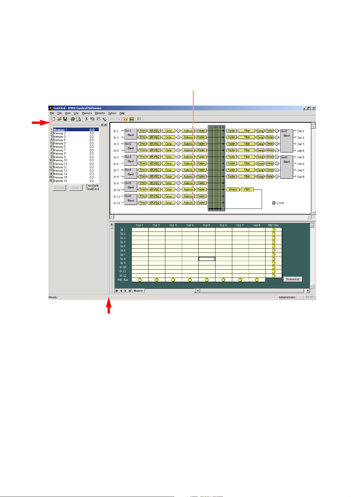
76
19. VIEW DISPLAY SWITCHING (SUPPLEMENT)
Both docking and floating displays are possible in each view except the flow view.
19.1. Docking Displays
In the following example, the docking display screen is shown.
Flow view (fixed)
Clicking the window border (indicated by the arrow) switches the docking display to the floating display.
Page 77

77
19.2. Floating Displays
In the following example, the memory view is shown in a floating display.
• Floating displays can be switched to docking displays by double-clicking on the title bar.
• The display can also be switched to a docking display by dragging-and-dropping the title bar to the desired
location.
• The memory display can also be switched from the menu.
• The floating display can be moved and its display size changed.
• When moving, right-click on the title bar to select "Move" from the pull-down menu, then drag-and-drop the
title bar.
Note
If the title bar is dragged-and-dropped without selecting "Move" from the pull-down menu, a docking display
may appear in that location, depending on where it was dropped. To move floating displays, be sure to
select "Move" first.
• To change the display size, click on and drag the window border to adjust. However, the size of the memory
view cannot be changed.
Page 78

78
20. SPECIFICATIONS
20.1. Software Specifications
Operating System: Microsoft Windows 98 SE/Me/2000 and Windows XP
Preset Memory: 16 memories
20.2. Communication Specifications
Communication Method: RS-232C
Transmission Rate: 115200 bps (38400 bps, 19200 bps, 9600 bps)
Data Bit: 8 bits
Stop Bit: 1 bit
Parity: Non-parity
Connection Cable: RS-232C straight cable
20.3. Setting Items and Setting Ranges
Note: Underlined parameters are factory-preset.
20.3.1. Signal processing box
[Input and Output/Trim Settings]
Setting Item Setting Range
Input Channel Gain –∞ to +10 dB
Input Trim Gain –15 to +15 dB (0 dB
), 0.1 dB steps
Input Trim Polarity NORMAL, INVERSE
Input Channel Group Trim Gain –∞ to +10 dB, 0.1 dB steps
Output Channel Gain –∞ to +10 dB (0 dB
)
Output Channel Group Trim Gain –∞ to +10 dB, 0.1 dB steps
[High-Pass Filter Settings]
Setting Item Setting Range
Cutoff Frequency 20 Hz – 20 kHz (60 Hz), 1/24 octave steps
Slope 12 dB/oct
Q 0.500 – 2.563 (0.707
) (51 points)
ON/OFF ON, OFF
[Equalizer Settings]
Setting Item Setting Range
Gain –15 to +15 dB (0 dB), 0.1 dB steps
Center Frequency 20 Hz – 20 kHz (Low: 630 Hz, High: 1.25 kHz), 1/24 octave steps
Q 0.267 – 69.249 (4.318) (96 points)
ON/OFF ON, OFF
[Compressor/Auto-Leveler Mode Settings]
Setting Item Setting Range
Compressor/Auto-Leveler Mode COMP, LEVELER
Page 79

79
[Auto-Leveler Settings]
Setting Item Setting Range
Target Level –20 to +10 dB (0 dB), 1 dB steps
Maximum Gain 0 to +20 dB (+6 dB), 1 dB steps
Attack Time 10, 20, 50, 70, 100, 120, 150, 200, 250, 300, 500
, 700 ms,
1, 1.2, 1.5, 2, 2.5, 3, 5, 7, 10 s
Release Time 100, 120, 150, 200, 250, 300, 500, 700 ms,
1, 1.2, 1.5, 2, 2.5, 3, 5, 7, 10 s
ON/OFF ON, OFF
[Compressor Settings]
Setting Item Setting Range
Threshold Level –20 to +20 dB (0 dB), 1 dB steps
Ratio 1:1, 2:1, 3:1, 4:1, 8:1, 12:1, 20:1, ∞:1
Attack Time 0.2, 0.5, 0.7, 1.0, 1.5, 2, 3, 5, 7, 10
, 20, 50, 70, 100, 120, 150, 200,
250, 300, 500, 700 ms
1, 2, 3, 5 s
Release Time 10, 20, 50, 70, 100, 120, 150, 200, 250, 300, 500
, 700 ms
1, 2, 3, 5 s
Gain –∞ to +10 dB (0 dB), 1 dB steps
ON/OFF ON, OFF
[Effect (Echo) Settings]
Setting Item Setting Range
Echo Gain –∞ to 10.0 dB (–10 dB), 1 dB steps
Feedback Ratio 0 – 99% (30%), 1% steps
Feedback Delay 0 – 682 ms (120 ms
), 1 ms steps
Initial Echo (Pre-) Delay 0 – 682 ms (80 ms), 1 ms steps
Low-pass Filter Frequency 20 Hz – 20 kHz (3.75 kHz)
Q 0.500
– 2.563 (51 points)
ON/OFF ON, OFF
Page 80

80
[Matrix (Bus Assignment and Crosspoint Gain) Settings]
Setting Item Setting Range
Input 1
Output 1 – 8: ON, OFF
Microphone Bus: ON, OFF
Input 2 – 12 Same as the above
Microphone Bus
Output 1 – 8: ON, OFF
Gain
–∞ to 0 dB
, 1 dB steps
[Crossover Settings]
Setting Item Setting Range
Cutoff Frequency 20 Hz– 20 kHz (1 kHz), 1/24 octave steps
Slope Through, 6 dB/oct, 12 dB/oct BS, 12 dB/oct VQ 24 dB/oct VQ
BS: Bessel 12 dB/oct BW, 12 dB/oct LR, 18 dB/oct BS, 18 dB/oct VQ
BW: Butterworth 18 dB/oct BW, 24 dB/oct BS, 24 dB/oct BW,
LR: Likwitz-Riley 24 dB/oct LR
VQ: Variable Q
Q 0.500– 2.563 0.500– 2.563
(51 points) (51 points)
Q2 0.500– 2.563
(51 points)
GAIN
–
15 to +15 dB (0 dB), 0.1 dB steps
Polarity NORMAL, INVERSE
Note: The initial value of the cut-off frequency differs depending on the crossover combination settings.
Combination Cut-off Frequency Initial Value
Single Ch.N HPF: 125 Hz, LPF: 125 Hz
2way Ch.N HPF: 20 Hz, LPF: 2.9 kHz
Ch.N+1 HPF: 2.9 kHz, LPF: 20 kHz
3way Ch.N HPF: 20 Hz, LPF: 500 Hz
Ch.N+1 HPF: 500 Hz, LPF: 2.9 kHz
Ch.N+2 HPF: 2.9 kHz, LPF: 20 kHz
4way Ch.N HPF: 20 Hz, LPF: 125 Hz
Ch.N+1 HPF: 125 Hz, LPF: 1 .25 kHz
Ch.N+2 HPF: 1.25 kHz, LPF: 8 kHz
Ch.N+3 HPF: 8 kHz, LPF: 20kHz
Page 81

81
[Delay Time Settings]
Setting Item Setting Range
Delay Time 0 – 682.6 ms, 0.021 ms steps
ON/OFF ON, OFF
Filter Type Setting Item Setting Range
Parametric Equalizer Gain –15 to +15 dB (0 dB), 0.1 dB steps
(PEQ) Center frequency 20 Hz – 20 kHz (1 kHz), 1/24 octave steps
Q 0.267 – 69.249 (96 points)
High-pass Filter (HPF) Cutoff frequency 20 Hz – 20 kHz (1 kHz
), 1/24 octave steps
Slope
6 dB/oct 12 dB/oct
Q 0.500 – 2.563 (51 points)
Low-pass Filter (LPF) Cutoff frequency 20 Hz – 20 kHz (1 kHz
), 1/24 octave steps
Slope
6 dB/oct 12 dB/oct
Q 0.500 – 2.563 (51 points)
High Shelving Filter Gain –15 to +15 dB (0 dB
), 0.1 dB steps
Rolloff frequency 6 – 20 kHz, 1/24 octave steps
Low Shelving Filter Gain –15 to +15 dB (0 dB
), 0.1 dB steps
Rolloff frequency 20 – 500 Hz, 1/24 octave steps
Horn Equalizer (Horn EQ)
Gain 0 to +18 dB, 0.5 dB step
Notch Filter Center frequency 20 Hz – 20 kHz (1 kHz), 1/24 octave steps
Q 8.651, 9.889, 11.538, 13.847, 17.310,
23.081, 34.623, 69.249
All-pass Filter Center frequency 20 Hz – 20 kHz (1 kHz), 1/24 octave steps
Q 0.267 – 69.249 (96 points)
ON/OFF ON, OFF
[Filter Settings]
[Feedback Suppression Function Settings]
Parameter Setting Item Setting Range
DYNAMIC Dynamic mode ON/OFF ON, OFF
AUTO START Auto mode activation
AUTO : DYNAMIC Number of the filters used in each mode AUTO : 0 – 9 (7), DYNAMIC : 3 – 12 (5)
CLEAR DYNAMIC Initialization of Dynamic mode filter
CLEAR AUTO Initialization of Auto mode filter
[Feedback Suppression Filter Setting]
Setting Item Setting Range
Gain –15 to +15 dB, 0.1 dB steps
Center Frequency 20 Hz – 20 kHz, 1/24 octave steps
Q 0.267 – 69.249 (96 points)
Note: Automatically set by the D-901 Mixer's software.
Page 82

82
20.3.2. Auto mixing function
[Gate Settings]
Setting Item Setting Range
Threshold Level –50 to +20 dB (–40 dB
), 1 dB steps
Hysteresis 0 to +10 dB, 1 dB steps
Depth –∞ to 0 dB (–20 dB), 1 dB steps
Hold Time 10
, 20, 50, 70, 100, 120, 150, 200, 250, 300, 500, 700 ms,
1, 2, 3, 5, 10 s
Attack Time 10, 20, 50, 70, 100, 120, 150, 200, 250, 300, 500, 700 ms,
1, 2, 3, 5, 10 s
Release Time 10, 20, 50, 70, 100, 120, 150, 200, 250, 300, 500, 700 ms,
1, 2, 3, 5, 10 s
ON/OFF ON, OFF
[Ducker Settings]
Setting Item Setting Range
Priority Level 1 –8 (in order of the priority level from high to low)
Depth
–
∞ to 0 dB (–20 dB
), 1 dB steps
Attack Time 10
, 20, 50, 70, 100, 120, 150, 200, 250, 300, 500, 700 ms,
1, 2, 3, 5, 10 s
Release Time 10
, 20, 50, 70, 100, 120, 150, 200, 250, 300, 500, 700 ms,
1, 2, 3, 5, 10 s
ON/OFF ON, OFF
[NOM Attenuation Settings]
Setting Item Setting Range
Attenuation Gain
0 log10
NOM – 20 log10 NOM (10
)
ON/OFF ON, OFF
[Level Sense Settings]
Setting Item Setting Range
Attack Time 0.2, 0.5, 0.7, 1.0, 1.5, 2, 3, 5, 7, 10, 20, 50, 70, 100, 120, 150, 200,
250, 300, 500, 700 ms
1, 2, 3, 5 s
Release Time 10, 20, 50, 70, 100, 120, 150, 200, 250, 300, 500, 700 ms,
1, 2, 3, 5 s
20.3.3. Settings when the D-921E or D-921F is used
Setting Item Setting Range
Phantom Power ON, OFF
PAD (Input Sensitivity) –50, –36, –10, +4
dB
[Auto-Mixing Group Settings]
Setting Item Setting Range
Auto-Mixing Group GROUP A, GROUP B, GROUP C, GROUP D
Page 83

200412
20.3.5. Settings when the D-937SP is used
Setting Item Setting Range
Line Sel 1, 2, 3, 4
20.3.4. Settings when the D-936R is used
Setting Item Setting Range
Line Input Mode MIX ALL, SELECT
Line Selection 1, 2, 3, 4 (
factory-preset: all On)
20.3.6. Settings when the D-981, D-983, or D-984VC is used
20.3.7. Preset Memory Settings
[Preset memory crossfade time setting]
Setting Item Setting Range
Crossfade Time 0
– 10 s, 0.5 s steps
Setting Item Setting Range
Contact Input Memory (factory-preset: 1 – 8), Volume Up/Down, Channel On/Off
Stereo input, None
(factory-preset: 9 – 24)
Contact Output Normally break
(factory-preset: 9 – 24), Normally make,
Memory (factory-preset: 1 – 8), Channel On/Off,
Contact input status, Stereo input
[Initial preset memory settings]
Setting Item Setting Range
Preset Memory LAST MEMORY
, 1 – 16
 Loading...