

Page 1
Operating Instruction Manual
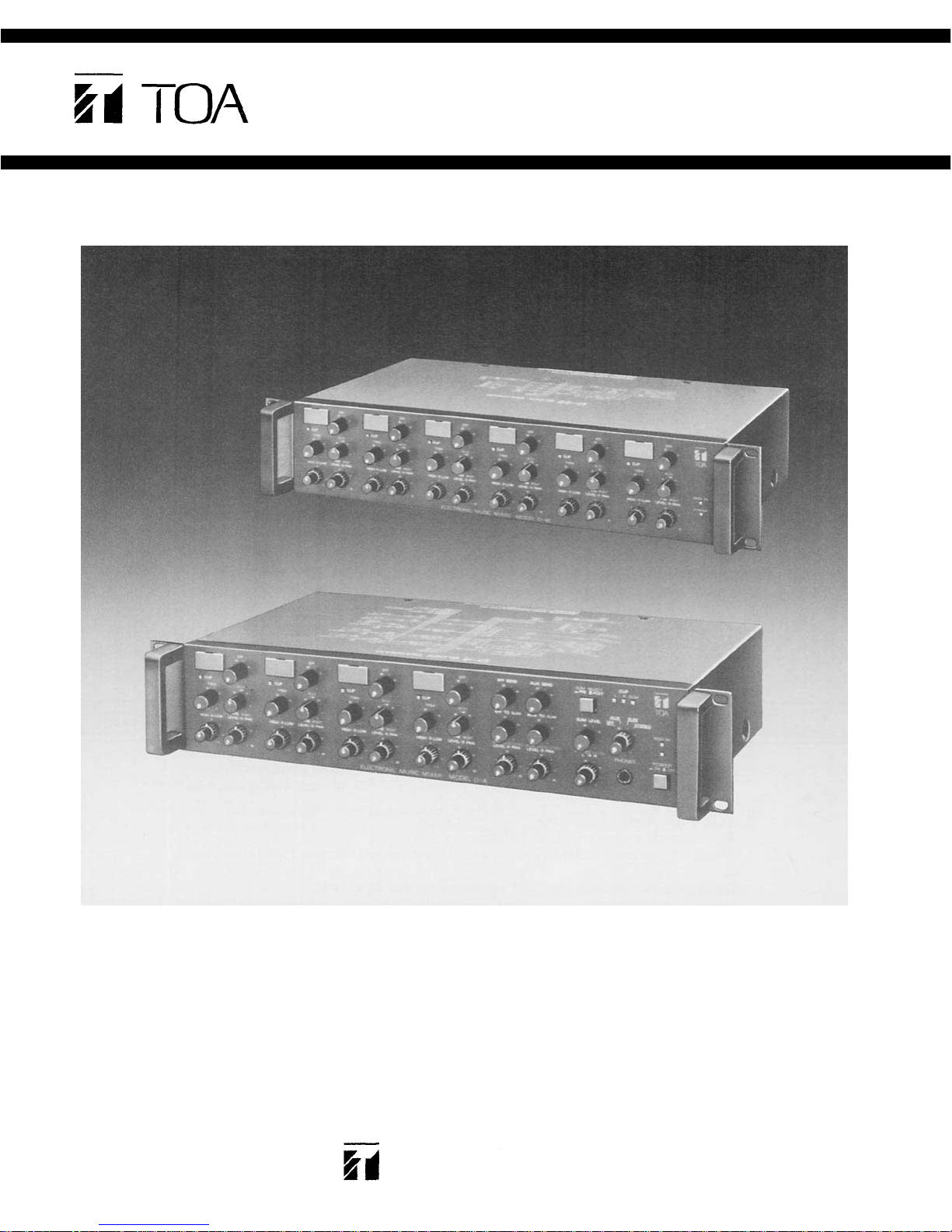
ELECTRONIC MUSIC MIXER
Model D-4, D-4E
D-4
D-4E
Toa Electric Co., Ltd.
KOBE JAPAN
Page 2

Contents
General Description ..................................................................... 2
Features .................................................................................... 3
Front Panel: Names of components & their usage [D-4] ...................... 4
Rear Panel: Names of components & their usage [D-4] ....................... 5
Front Panel [D-4E] ....................................................................... 6
Rear Panel [D-4E] ........................................................................ 6
Block and Level Diagrams ............................................................ 7
Specifications [D-4, D-4E] ............................................................. 8
Procedure for Changing internal Switch Settings .............................. 9
Characteristics Diagrams .............................................................. 10
Appearance ................................................................................ 10
Precautions
1. XLR Type Audio Connector
The connectors are wired as follows.
The pin 1 is ground (shield), the pin 2 cold (low, minus), the pin 3 hot (high, plus).
2. Description of components and functions on the D-4, D-4E
Various descriptions are applied, depending on each manufacturer. In our
Operating and Instruction Manual explanation of components and functions is
made according to our usage for them.
- 1 -
Page 3

General Description
The TOA D-4 is a 19" rack mountable, four input stereo mixer especially designed for
electronic music. When combined with the D-4E, the matching six input expander,
the D-4 becomes a ten input mixer with five balanced XLR inputs, stereo and mono
outputs, and eight MIDI Thru jacks. The D-4 is ideal for live use, home recording, or
broadcast work.
Each of the D-4's inputs features a writing block for identifying the input source, a trim
control with a range of 34dB, an LED clip indicator, an Aux (auxiliary) send (internally
switchable from post-EQ to pre-EQ, and selectable on the front panel between
pre-fader and post-fader), an Effects send (post-fader/post-EQ), concentric bass and
treble controls, and concentric stereo pan and volume controls. The D-4's output
section features master level controls for both Effects and Aux sends, master level
controls to return Effect and Aux to mono sum and to stereo L&R with pan, master
volume controls for stereo L&R and mono sum, a switch to derive the mono sum from
either pre-fader or post-fader stereo busses, and LED clip indicators for L, R, and Sum
outputs. The head phone output jack is also located on the front panel, along with the
head phone volume control and cue select switch.
The rear panel of the D-4 features RCA and 1/4" phone input jacks, accessory patch
points (switchable internally from post-fader/post-EQ to pre-fader/pre-EQ), and direct
outputs for each input channel. In addition, input channel 4 is equipped with a
balanced XLR input and switchable 48 volt phantom power. The stereo L&R outputs
are 1/4" phone jacks and RCA jacks, while the mono sum out features an XLR
electronically balanced output with ground lift switch, and a 1/4" phone jack. Stereo
L&R and Sum outputs all feature accessory patching, and there is a separate 1/4" phone
input direct to the mono sum buss.
The D-4's MIDI jacks are also located on the back panel. One MIDI input jack is split
into four MIDI Thru jacks, allowing the use of multiple synthesizers without the
problems of data corruption and delay that occur when connecting many synths in
series through their internal MIDI Thru jacks.
A pushbutton circuit breaker and chassis ground post is located on the back of the D-4,
as is a 6-foot AC power cord.
The D-4E is a six input expander designed to be used exclusively with the D-4. Each
input channel has the same controls and jacks as the D-4, but the D-4E has four
balanced XLR inputs, each with its own 48 volt phantom power when combined with
the D-4 give a total of eight MIDI Thru jacks. The D-4E features a buss link jack located
on the back panel to connect it to the D-4, with the included 2-foot buss-connect cord
(a 6-foot connecting cord is optional — see your authorized TOA dealer). There is also a
switched accessory outlet on the back of the D-4, allowing both units to power up with
the same on/off switch.
Both the D-4 and D-4E can be mounted in a standard 19" rack, and each occupies two
rack spaces. Removable rack ears are included. The mixers are finished in an attractive
gray enamel finish.
- 2 -
Page 4

Features
1. Four input channels, total ten input channels when combined with D-4E
2. MIDI Thru circuitry with one MIDI In jack and four MIDI Thru jacks (total eight
3. Stereo Left and Right outputs with both RCA and 1/4" jacks
4. Five busses (Stereo L, R, Eff, Aux, and Sum) for maximum flexibility
5. Independent Eff and Aux return to Stereo L&R and to Sum
6. Individual accessory patch points for Stereo L&R and Sum for best signal-to-noise
7. Sum output features electronically balanced XLR connector and unbalanced 1/4"
8. Head phone monitoring for Stereo L&R, Sum, Eff, and Aux
9. Pushbutton circuit breaker for protection
10. 19" rack mounting bracket included is removable for use outside of rack
MIDI Thru jacks when combined with D-4E) for convenience and protection against
data loss or delay
ratio
phone jack
Each Channel
1. Input trim control with LED clip indicator for best signal-to noise ratio
2. Two band EQ
3. Accessory patch point is factory preset to be post-fader/post-EQ, internally
switchable to pre-fader/pre-EQ
4. Aux send is factory preset to be post-EQ, internally switchable to pre-EQ
5. Aux level control on the front panel derives signal from either pre-fader or
post-fader with center detent position being "off"
6. Independent effect send is post-fader/post-EQ
7. Direct output on each channel, ideal for recording
8. Concentric stereo pan and channel volume control
9. Input Channel 4 on D-4 has electronically balanced XLR input connector with
switchable 48 volt phantom power, as do Channels 5, 6, 7, and 8 on D-4E
- 3 -
Page 5

Front Panel (D-4)
The name of the inp ut eq uip men t
can be written in with an erasable
felt pen or grease pencil.
Clip LED Indicator (CLIP)
The LED indicator lights when
the pre or post EQ signal level
reaches 3dB below clipping, giv-
ing a visual reference for opti-
Writing Block
mum setting of the trim control.
Input Trim Control (TRIM)
The trim control adjusts the gain
of the preamp stage of the associated channel, providing 34 dB of
gain control. When the trim con-
trol is set to the "0" position, the
nominal input level is -30 dB. At
the "–34" position the level is
+4dB. When the input channel
four(4) for mic input is used, the
nominal input level is –60dB at
the "0" position of the trim con-
trol. At the "–34dB" position the
level is –26dB.
The trim control of each channel
should be adjusted so that the
clip LED just begins to light, or
only flashes occasionally. This
will ensure lowest distortion
level and optimum signal to noise
ratio.
High Equalizer Control
The high EQ control alters the
high frequency response of the
input channel, providing ±10dB
at 4kHz, and ±15dB at 20kHz of
continuously variable active
shelving equalization. The "0"
detented position provides flat
audio response.
Low Equalizer Control (LOW EQ)
The low EQ control provides
±10dB at 150Hz and ±15dB at
20Hz of continuously variable active shelving equalization. The
"0" detented position provides
flat audio response.
Input Channel Level and Pan
This control governs the amount
of post-EQ signal assigned to the
Stereo L&R busses and to the
mono Sum buss. It includes both
a level control and a concentric
pan control, which determines
the placement of the signal in the
stereo image.
(HIGH EQ)
(LEVEL/PAN)
Effects Control (EFF)
This control determines the
amount of post-fader/post-EQ sig-
nal assigned to the effect buss
from a given input channel, and
thus the level of effects for that
channel.
Aux
Control
This control determines the level
of the input signal to be fed to the
aux buss. When in the center
detent position the control is off,
and no signal is assigned. Rotat-
ing the control counter-clockwise
increases the amount of pre-fader/
post-EQ signal assigned to the
buss, while rotating the control
clockwise increases the amount
of post-fader signal assigned to the
buss. The pre-fader/post-EQ signal can be changed to pre-EQ
signal with an internal switch
(see page 9).
This control determines the
amount of effect signal returned
to the mono Sum buss through
the Effect Return Jack on the rear
panel (EFF RET).
This control determines the
amount of aux signal returned to
the mono Sum buss through the
Aux Return Jack on the rear panel
(AUX
(AUX)
Effect to Sum Level Control
Aux to Sum Level Control
(EFF
(AUX
TO
TO
SUM)
SUM)
RET).
Master Effect Send Control
(EFF SEND)
This control governs the overall
level of signal sent to an outboard
effect device through the Effect
Send Jack on the rear panel (EFF
SEND).
Master Aux Send Control
(AUX SEND)
This control governs the overall
level of signal sent to on-stage
monitor amplifiers, or an outboard effect device through the
Aux Send Jack on the rear panel
(AUX SEND).
Effect Return to Stereo Level
Control (EFF TO STEREO/PAN)
This control governs the amount
of effect signal returned to Stereo
L&R through the EFfect REturn
Jack (EFF RET). It includes both a
level control and a concentric
stereo pan control, which deter-
mines the placement of the effect
signal in the stereo image.
Aux REturn to Stereo Level
Control (A UX TO STEREO)
This control governs the amount
of aux signal returned to Stereo
L&R through the Aux Return Jack
(AUX RET). It includes both a
level control and a concentric
stereo pan control, which deter-
mines the placement of the aux
signal in the stereo image.
Sum Pre/Post Select Switch
(SUM SELECT)
The mono Sum signal is derived
by su mmi ng the Stereo L&R sig-
nals. The Sum Select switch de-
termines whether this summing
occurs before or after the Master
Stereo Faders. When using the
switch in the Pre-position, the
Sum output level is independent
of the Master Stereo L&R level
controls. In the Post-position, ad-
justing the Master Stereo L&R
level controls will affect the
volume of the Sum output.
Master Sum Level Control
(SUM LEVEL)
This control determines t he overall level of the Sum output (SUM
OUT).
LED Clip Indicators (CLIP)
The L, R, and Sum clip indicators
light when their respective signals reach 3dB below clipping,
giving a visual indication before
the onset of distortion.
Head phone Selector, Level
Control, and Jack (PHONES)
An output jack, volume control,
and four-position rotary switch is
provided for the use of head
phones. Any one of four busses
can be monitored through head
phones using the selector switch:
EFF, AUX, SUM, or STEREO. All
monitored signals are in mono
with the exception of Stereo L&R
which are monitored, of course,
in stereo. The level control adjusts the volume of the head
phones, and the head phone jack
will accept any stereo head
phones with and impedance of
eight ohms or more.
MIDI LED Indicator (MIDI IN)
This LED indicates the presence
of MIDI data at the MIDI input
jack on the rear panel (MIDI IN).
Power LED Indicator and Switch
(POWER)
The power switch alternately
turns AC power to the D-4 and to
the accessory AC outlet "on" and
"off". The LED indicator lights
when the switc h is "on".
Master Stereo L&R Level
Controls (STEREO LEVEL)
These concentric controls deter-
mine the overall level of the
Stereo L&R ou tputs (ST L and ST
R).
- 4 -
Page 6

Rear Panel (D-4)
MIDI Thru Connectors
The MIDI signal from the MIDI Input
connector (MIDI IN) is split and sent
unaltered to the four MIDI Thru
connectors on the D-4, and to four
more MIDI Thru connectors on the
D-4E, if used. Each of the MIDI Thru
jacks can be connected to a different
synthesizer's MIDI Input jack, allow-
ing one MIDI keyboard or sequencer
to control up to four other MIDI
synths (eight when using the D-4E.)
(PUT EARTH SYMBOL HERE)
This terminal can be used to ground
other devices to the D-4 to reduce
hum and shock hazard.
The power cord is of the three-wire
type with proper grounding facili-
ties built-in.
Accessory Switched AC outlet
This is an accessory AC outlet that is
turned on and off via the D-4's
Power Switch. Ideally it will be used
for the D-4E, allowing both units to
be powered up on the same switch,
but it will in fact handle any AC
equipment that consumes less than
400 watts.
(MIDI THRU)
Earth Terminal
AC Power Cord
Sum Output Ground Lift Switch
This switch is assigned to the XLR
Sum Output connector, and is used
to avoid ground loops and induced
hum that sometimes occur when
connecting the D-4's XLR Sum Out-
put with other equipment. Sliding
the Ground Lift Switch from the
NORMAL position to the LIFT posi-
tion breaks the ground connection
and may reduce hum and noise. For
most applications the which should
be left in the NORMAL position.
Stereo L&R Accessory Input and
Output Jacks (ST L and ST R, ACC
These RCA pin jacks are unba-
lanced, with a nominal level of
-10dB. Input jack impedance is 10k
ohms, and output jack impedance is
1k ohms. The Accessory jacks allow
signal processing and effect devices
to be inserted into the signal path,
the regular signal path is interrupted
when a plug is inserted into the
Accessory In jack (ACC IN ).
MIDI Input DIN Connector
(MIDI IN)
This connector will accept the MIDI
output of any synthesizer, se-
quencer, or other MIDI device. Use
of non-MIDI-standard DIN cables, or
of cables longer than 5m (16'5") may
result in improper operation and
data loss.
(SUM
OUT
IN and
GND)
OUT)
Direct Output (DIRECT OUT)
The Direct Output on each channel
utilizes an unbalanced RCA pin jack
with an impedance of 1k ohms and a
level of – 10dB. The Direct Outp ut is
post-EQ/post-fader, and is useful for
recording and for sending individual instruments to a main PA
mixer through direct boxes.
Sum Accessory Input and Outp ut
(SUM
OUT,
These RCA pm jacks are unbalanced, with a nominal level of
–10dB. Input jack impedance is 10k
ohms, and output jack impedance is
1k ohms. The Accessory jacks allow
signal processing and effect devices
to be inserted into the signal path.
The regular signal path is inter-
rupted when a plug is inserted into
the Accessory In ja ck (ACC IN).
ACC IN and ACC
OUT)
Aux Send Jack (AUX SEND)
This 1/4" phone jack can be used
either as a monitor send, or in
conjunction with the Aux Return
jack to connect an outboard effects
device (ie., delay or reverb) to the
D-4. The Effect Send |ack should be
connected to the input of the effect.
Nominal output level is –10dB with
an impedance of 1k ohms.
Input Channel Accessory Input and
Output (ACC IN and ACC OUT)
These RCA pin Jacks are unba-
lanced, with a nominal level of
–10dB. Input jack impedance is 10k
ohms, and output jack imped ance is
1k ohms. The Accessory jacks allow
signal processing and effect devices
to be inserted into the signal path
The regular signal path is inter-
rupted when a plug is inserted into
the Accessory In jack (ACC IN).
RCA Channel Input (INPUT)
The RCA pin input jack is unba-
lanced, with an impedance of 50k
ohms, and accepts input sources
from –30dB to +4dB. Proper adjustment of both Trim control (TRIM)
and Input Channel Level (LEVEL/
PAN) control will insure optimum
signal-to-noise ratio and m inimum
distortion.
1/4" Phone Channel Input (INPUT)
This |ack is a standard, unbalanced
1/4" phone jack, with an input impe-
dance of 50k ohms, and accepts
input sources from -30dB to +4dB.
Proper adjustment of both Trim control (TRIM) and Input Channels
Level (LEVEL/PAN) control will insure op timu m signal-to-noise ratio
and min imu m distortion. When a
plug is inserted into the 1/4" input
jack, the corresponding RCA pin
jack is automatically switched out of
the input circuitry.
Pushbutton Circuit Breaker
This breaker is designed to protect
the D-4 and D-4E in the event of
internal or external fault. Wait about
two minutes after correcting the
fault and push the button to reset the
system and restore proper operation.
Buss Link Connector (BUSS LINK)
This connector is used to link the
D-4 with the D-4E Expander. A
two-foot connecting cord is included with the D-4E, and a six-foot
cord is optional (see your authorized
TOA dealer).
(PUSH RESET)
CAUTION – The ground pin on
the AC plug should not be re-
moved under any circumstances.
If the D-4 must be used on an AC
circuit with no ground or and
open ground, then a suitable
grounding adapter should be
used and its ground terminal
should be securely attached to a
good earth connection. Failure to
do so will result in increased
noise and shock hazard.
Sum Output Jacks
The electronically balanced XLR
and unbalanced 1/4" phone are
wired in parallel. The XLR jack has a
nominal output level of +4dB and
an impedance of 150 ohms, while
the 1/4" jack has a nominal output
level of +4dB and an impedance of
1k ohms. These jacks may be used
simultaneously.
Stereo L&R Output Jacks
(ST L and ST R OUTPUT)
The unbalanced RCA pin jacks and
1/4" phone jacks are wired in para-
llel. The RCA jack has a nominal
output level of –10dB and an impedance of 1k ohms, while the 1/4" jack
has a nominal output level of +4dB
and an impedance of 1k ohms. The
jacks may be used simultaneously.
(SUM OUT, OUTPUT)
Effec t Return Jack (EFF RET)
This 1/4" phone jack is used in
conjunction with the Effect Send
jack to connect an outboard effects
device (ie., delay or reverb) to the
D-4. The Effect Return jack should
be connected to the output of the
effect. Nominal inp ut level is -20dB
with an impedance of 10k ohms.
Aux Return Jack (A UX RET)
This 1/4" phone jack can be used in
conjunction with the Aux Send jack
to connect an outboard effects de-
vice (ie., delay or reverb) to the D-4.
The Aux Return jack should be
connected to the output of the effect.
Nominal input level is -20dB with
an impedance of 10k ohms.
Sum Input Jack (SUM IN)
This 1/4" phone jack is directly
connected to the mono Sum buss. Its
nominal input level is –10dB, with
an input impedance of 10k ohms.
Phantom Power On/Off Switch
(PHANTOM)
This switch alternately turns "on"
and "off" the phan tom power
(48VDC) for the XLR jack assigned to
Channel 4.
Balanced XLR Microphone Input
(CH4
MIC)
The XLR-type microphone input
connectors are assigned to Channels
4 on the D-4. and to Channels 5, 6, 7,
and 8 on the D-4E. They are electronically balanced with an input impedance of 1k ohms, and wil l accept
signals from –60dB to –26dB. Phan-
tom powering is provided for use
with condenser-type microphones
(see PHANTOM), and once again the
proper adjustment to both Trim con-
trol (TRIM) and Input Channel Level
(LEVEL/PAN) control wi ll insure
optimum signal-to-noise ratio and
minimum distortion. The mic input
is automatically disconnected when
either the corresponding RCA or the
1/4" phone |ack is used.
Effect Send Jack (EFF SEND)
This 1/4" phone jack is used in
conjunction with the Effect Return
jack to connect an outboard effects
device (ie., delay or reverb) to the
D-4. The Effect Send jack should be
connected to the input of the Effect.
Nominal output level is –10dB with
an impedance of 1k ohms.
- 5 -
Page 7

Front Panel (D-4E)
The name of the input equipment
can be written in with an erasable
felt pen or grease pencil.
Clip LED Indicator (CLIP)
The LED indicator lights when the
pre or post EQ signal level reaches
3dB below clipping, giving a visual
reference for optimum setting of the
trim control.
Input Trim Control (TRIM)
The trim control adjusts the gain of
the preamp stage of the associated
channel, providing 34 dB of gain
control. When the trim control is set
to the "0" position, the nominal
inpu t level is –30 dB. At the "–34"
position the level is +4dB. When the
inp ut channels five (5) thru eight (8)
for mic input are used, the nominal
input level is -60dB at the "0"
position of the trim control. At the
"–34dB" position the level is –26dB.
The trim control of each channel
should be adjusted so that the clip
LED just begins to light, or only
flashes occasionally. This will en-
sure lowest distortion level and opti-
mum signal to noise ratio.
Writing Block
Effects Control (EFF)
This control determines the amount
of post-fader/post-EQ signal
assigned to the effect buss from a
given input channel, and thus the
level of effects for that channel.
High Equalizer Control (HIGH EQ)
The high EQ control alters the high
frequency response of the input
channel, providing ±10dB at 4kHz,
and ±15dB at 20kHz of continuously variable active shelving equaliza-
tion. The "0" detented position pro-
vides flat audio response.
Low Equalizer Control (LOW EQ)
The low EQ control provides ±10dB
at 150Hz and ±15dB at 20Hz of
continuously variable active shelv-
ing equalization. The "0" detented
position provides flat audio response.
Aux Control (A UX)
This control determines the level of
the input signal to be fed to the aux
buss. When in the center detent
position the control is off, and no
signal is assigned. Rotating the con-
trol counter-clockwise increases the
amount of pre-fader/post-EQ signal
assigned to the buss, while rotating
the control clockwise increases the
amount of post-fader signal assigned
to the buss. The pre-fader/post-EQ
signal can be changed to pre-EQ
signal with an internal switch (see
page 9).
Input Channel Level and Pan
(LEVEL/PAN)
This c ontrol governs the amoun t of
post-EQ signal assigned to the Stereo
L&R busses and to the mono Sum
buss. It includes both a level control
and a concentric pan control, which
determines the placement of the
signal in the stereo image.
Rear Panel (D-4E)
Direct Output (DIRECT OUT)
The Direct Output on each channel
utilizes an unbalanced RCA pin jack
with an impedance of 1k ohms and a
level of –10dB. The Direct Output is
post-EQ/post-fader, and is useful for
recording and for sending individual instruments to a main PA
mixer through direct boxes.
MIDI Thru Connectors
The MIDI signal from the MIDI input
connector (MIDI IN) is split and sent
unaltered to the four MIDI Thru
connectors on the D-4, and to four
more MIDI Thru connectors on the
D-4E, if used. Each of the MIDI Thru
jacks can be connected to a different
synthesizer's MIDI input jack, allow-
ing one MIDI keyboard or sequencer
to control up to four other MIDI
synths (eight when using the D-4E.)
Buss Link Connector (BUSS LINK)
This connector is used to link the
D-4 with the D-4E Expander. A
two-foot connecting cord is in-
cluded with the D-4E, and a six-foot
cord is optional (see your authorized
TOA dealer).
(PUT EARTH SYMBOL HERE)
This terminal can be used to ground
other devices to the D-4 to reduce
hum and shock hazard.
(MIDI THRU)
Earth Terminal
Input Channel Accessory Input and
Output (ACC IN and ACC OUT)
These RCA pin Jacks are unbalanced, with a nominal level of
–10dB. Input jack impedance is 10k
ohms, and output jack impedance is
1k ohms. The Accessory jacks allow
signal processing and effect devices
to be inserted into the signal path.
The regular signal path is inter-
rupted when a plug is inserted into
the Accessory In jack (ACC IN).
Pushbutton Circuit Breaker
(PUSH RESET)
This breaker is designed to protect
the D-4 and D-4E in the event of
inter nal or external fault. Wait about
two minutes after correcting the
fault and push the button to reset the
system and restore proper operation.
RCA Channel Input (INPUT)
The RCA pin input jack is unbalanced, with an impedance of 50k
ohms, and accepts input sources
from -30dB to +4dB. Proper adjustment of both Trim control (TRIM)
and Input Channel Level (LEVEL/
PAN) control will insure optimum
signal-to-noise ratio and minimum
distortion.
Phantom Power On/Off Switch
(PHANTOM)
This switch alternately turns "on"
and "off" the phantom power
(48VDC) for the XLR jack.
1/4" Phone Channel Input (INPUT)
This jack is a standard, unbalanced
1/4" phone jack, wi th an input impe-
dance of 50k ohms, and accepts
input sources from -30dB to +4dB.
Proper adjustment of both Trim con-
trol (TRIM) and Input Channels
Level (LEVEL/PAN) control will in-
sure optimu m signal-to-noise ratio
and minimum distortion. When a
plug is inserted into the 1/4" input
jack, the corresponding RCA pin
jack is automatically switched out of
the input circuitry.
Balanced XLR Microphone Input
(CH5
MIC,
CH6
MIC,
CH7
MIC,
CH8
The XLR-type microphone input
connectors are assigned to Channels
4 on the D-4, and to Channels 5, 6, 7.
and 8 on th e D-4E. They are electronically balanced with an input impedance of 1k ohms, and will accept
signals from -60dB to -26dB. Phan-
tom powering is provided for use
with condenser-type microphones
(see PHANTOM), and once again the
proper adjustment to both Trim con-
trol (TRIM) and Input Channel Level
(LEVEL/PAN) control will insure
optimum signal-to-noise ratio and
minimum distortion. The mic input
is automatically disconnected when
either the corresponding RCA or the
1/4" phone jack is used.
MIC)
- 6 -
Page 8

Block and Level Diagrams
D-4
BLOCK DIAGRAMS
LEVEL DIAGRAM
D-4E
BLOCK DIAGRAMS
LEVEL DIAGRAM
- 7 -
Page 9

Specifications (D-4, D-4E)
GENERAL SPECIFICATIONS
Frequency Response
+ 0dB, –0.5dB
+ 0dB, –3dB
Total Harmonic Distortion
0.05%
+4dB*
Hum and Noise [INPUT : SHORT CIRCUIT, OUTPUT : OPEN, 20Hz to 20kHz]
All Level Controls minimum
Stereo Level Control at max, and all Input Level
Controls minimum
Stereo Level Control and one Input Level Control
at max
Maximum Voltage Gain
Input to STEREO OUT
Mic Input to STEREO OUT
Input to SUM OUT
Input to EFF/AUX SEND
EFF/AUX RET to STEREO OUT
Equalization
LOW ±15dB 20Hz Shelving
HIGH ±15dB 20kHz Shelving
50Hz to 15kHz
20Hz to 25kHz
at
1kHz
–100dB*
–85dB* (D-4 ONLY)
–82dB* (D-4E CONNECTION)
–78dB* (S/N 82dB)
34dB
64dB
34dB
20dB
24dB
CLIP Indicator
Each input channel LED, and Master
section (L, R, SUM) LED's turn on at
3dB below clipping
Power Consumption
D-4 13W
D-4E 10W
Dimensions (W× D×H )
D-4,
D-4E
420×230×88.5mm
(16½×9×3½inch)
Weight
D-4 5kg (11lbs)
D-4E 5kg (11lbs)
Accessory (D-4E ONLY)
BUSS LINK CABLE 2ft. 1
BUSS LINK CABLE 6ft. (C6-D4) Option
* 0dB is referenced to 0.775V RMS.
Specifications are subject to change without
notice.
INPUT SPECIFICATIONS
Input
CHANNEL INPUT
CH1 ~ CH4
<CH5 ~ CH10>
MIC
INPUT
CH4
<CH5 ~ CH8>
ACCESSORY IN
(INPUT STEREO SUM)
EFF RETURN
AUX RETURN
SUM IN
Actual
Load
Impedance
50k
1k
10k
10k
10k
10k
OUTPUT SPECIFICATIONS
Output
STEREO O UT (L, R)
STEREO OUT (L, R)
SUM OUT UNBAL/BAL
EFF SEND
AU X SEND
DIRECT OUT
CH1 ~ CH4 <CH5 ~ CH10>
ACCESSORY OUT
(INPUT STEREO SUM)
PHONES
< > : D-4E ONLY
All XLR type connectors are electronically balanced.
Stereo phone jack is wired: Tip=Left, Ring=Right and Sleave=Common
Actual Source Impedance
1k
1k
1k
150
1k
1k
1k
1k
150
For Use
With
Nominal
50k
OR LOWER
IMP LINES
50
TO 25
MICROPHONES
10k
IMP LINES
10k
IMP LINES
10k
IMP LINES
10k
IMP LINES
0
OR LOWER
OR LOWER
OR LOWER
OR LOWER
For Use With Nominal
-30dB [25mV]
–60dB [0.78mV]
–10dB [250mV]
-20dB [78mV]
-20dB [78mV]
–10dB [250mV]
10k
10k
10k
600
10k
10k
10k
10k
or higher
8
- 8 -
Input Level (Trim "0" to Trim "–34")
Nominal
to +4dB [1.23V]
to –26dB [39mVJ
Nominal
+4dB [l.23V]
-10dB [250mV]
+4dB [1.23V]
–10dB [250mV]
–10dB [250mV]
–10dB [250mV]
–10dB[250mV]
–15dB [138mV]
Note:
The XLR type connectors are wired as follows.
Pin No. 1 — Grou nd
Pin No. 2 — Cold (Low)
Pin No. 3 — Hot (High)
MAX Before Clip
–14dB [155mV]
–44dB [4.9mV]
to –10dB [250mV]
+ 6dB [1.6V]
+6dB [1.6V]
+ 6dB [l.6V]
+ 6dB [1.6V]
Output Level
MAX Before Clip
+ 20dB [7.8V]
+ 6d B [l.6V]
+ 20d B [7.8 V]
+ 6d B [l.6V]
+6dB [l.6V]
+6dB [1.6V]
+ 6d B [l.6V]
-6dB [388mV]
to +20dB [7.8V]
0dB is referenced to 0.775V RMS.
Connector
PHONE JACK
RCA PIN JACK
XLR-3-31 TYPE
RCA PIN JACK
PHONE JACK
PHONE JACK
PHONE JACK
0dB is referenced to 0.775V RMS.
Connector
PHONE JACK
RCA PIN JACK
PHONE
JACK
PHONE JACK
PHONE JACK
RCA PIN JACK
RCA PIN JACK
STEREO
XLR
3-32 TYPE
PHONE JACK
Page 10

Procedure for changing internal switch setting
NOTE:
The internal switches have been provided for added
versatility when using the D-4 and D-4E in a variety of
applications.
1. ACCESSORY PATCH SELECT SWITCH: Each input
features an internal accessory "loop" (in/out) for in-line
patching of various outboard signal processing and
effects devices such as digital delays, equalizers, compressors, limiters, etc. Depending on the particular
device employed and/or effect desired, you may choose
to "patch" the external unit either before (pre), or after
(post) the input's EQ circuitry and level control. Typical-
ly, effects devices such as delays and reverb units are
patched "post" the EQ and level controls. In this
configuration, the level of the effect will be increased as
the level of the input channel is increased. The signal
sent to the external device will also be affected by the
input channel's EQ controls. On the other hand, you
may desire to patch such devices as limiters and
compressors "pre" so that their operation remains the
same, regardless of any changes in the input's EQ or
level controls.
2. AUX SEND PRE/POST EQ SELECTION SWITCH: Each
input features an auxiliary send control for use as either
an additional effects send, or as an on-stage monitor
send. You should note that the Aux control is a "split"
pot with the " " detent position (12o'clock) being the
off position. Typically, the control would be rotated
clockwise ("post") when used as an effects send. This
enables the effects level to be automatically increased as
the input channel level increases. Obviously, since this
signal is also derived "post" EQ, and changes made in
the input channel's EQ settings will be reflected in the
effects signal. When the AUX control is to be used as an
on-stage monitoring send, the control would typically be
rotated counter clockwise ("pre"). This allows the
on-stage monitor mix to operate independently of the
input channel's level control. In other words, any
change in the input channel's level control will not
affect the level of the monitor mix. The Aux Send
Pre/Post EQ Selection Switch is active only when the
Aux Control is used in the "pre" (counter clockwise)
position. When the switch is set to the "pre" EQ
position, the input channel's EQ controls will not affect
the on-stage monitor mix. This is particularly desirable
when the input source is a microphone. Since an
on-stage monitor system is normaly operated near
acoustic feedback, a change in EQ (especially an increase in high frequencies) may cause ringing or squeal-
ing (feedback) through the on-stage monitor speaker
system. However, when the input source is a synthesiz-
er, musical instrument, etc., that is not so susceptible to
feedback, you may desire to place the switch, in the
"post" EQ position so that the input channel EQ will
affect that instrument in the monitor mix.
Front Panel
Fig.l Fig.2
WARNING
The D-4 and D-4E contain voltage levels that may be
hazardous to human life. Always disconnect the power
cord from wall outlet prior to removing either unit's outer
case.
1. Disconnect the power cord from the wall outlet.
2. Remove the eight screws that secure the D-4/D-4E outer
case to the main chassis, and carefully remove the case.
(See
Fig 1)
3. Refer to block diagrams and Figure 2 for location and
orientation of switches.
Front panel
4. Set switches to desired positions.
5. Carefully replace the outer case and secure with eight
screws.
6. The Accessory patch switch is factory preset at "POST"
position (post-EQ/post-fader).
7. The Aux send pre/post EQ switch is factory preset at
"POST" position (post-EQ).
- 9 -
Page 11

Characteristics Diagrams
INPUT EQ CHARACTERISTICS
Frequency
Appearance
D-4
FREQUENCY RESPONSE
Frequency
D-4E
- 10 -
Page 12

Printed in Japan
133-02-727-70
 Loading...