

Page 1
SETTING SOFTWARE INSTRUCTIONS
DIGITAL MIXER D-2000 SERIES
(Ver. 4.2.0)
Thank you for purchasing TOA Digital Mixer.
Please carefully follow the instructions in this manual to ensure long, trouble-free use of your equipment.
Page 2

2
TABLE OF CONTENTS
1. GENERAL DESCRIPTION OF
THE D-2000 SETTING SOFTWARE
............................................................. 6
2. SOFTWARE SETUP
2.1. Installing the D-2000 Setting Software ............................................................... 7
2.2. Uninstalling the D-2000 Setting Software .......................................................... 9
3. STARTING THE SOFTWARE ....................................................................... 10
4. MAIN SCREEN AND MENU ITEM DESCRIPTION
4.1. Main Screen ..................................................................................................... 11
4.2. Menu Item Description
4.2.1. File ......................................................................................................... 12
4.2.2. Edit ......................................................................................................... 12
4.2.3. View ....................................................................................................... 12
4.2.4. Unit ......................................................................................................... 13
4.2.5. Memory .................................................................................................. 13
4.2.6. Communication ...................................................................................... 13
4.2.7. Option .................................................................................................... 14
4.2.8. Help ........................................................................................................ 14
5. UNIT CONFIGURATION AND SYSTEM-RELATED SETTINGS
5.1. D-2008SP Configuration Settings .................................................................... 15
5.2. D-2012C Configuration Settings ...................................................................... 24
5.3. Unit Change or Deletion and Slot Information Confirmation
5.3.1. Deleting the unit ..................................................................................... 25
5.3.2. Changing the unit configurations ........................................................... 25
5.3.3. Confirming the slot information .............................................................. 26
5.3.4. Changing the unit names ....................................................................... 27
6. MAIN SCREEN AFTER COMPLETION
OF UNIT CONFIGURATION
.......................................................................... 28
6.1. Unit View .......................................................................................................... 29
6.2. Connection Status View ................................................................................... 30
6.3. Memory View ................................................................................................... 31
6.4. Monitor View .................................................................................................... 33
6.5. Level Monitor View
6.5.1. When the D-2008SP is selected ............................................................ 34
6.5.2. When the D-2012C is selected .............................................................. 36
6.6. All Mute View ................................................................................................... 36
6.7. Routing Monitor View ....................................................................................... 37
7. D-2008SP FUNCTION SETTINGS
7.1. Flow View ......................................................................................................... 38
7.1.1. Input flow view ....................................................................................... 39
7.1.2. Bus flow view ......................................................................................... 40
7.1.3. Output flow view ..................................................................................... 41
7.2. Matrix View
7.2.1. Input Matrix view (Bus assignment and crosspoint gain settings) ......... 42
7.2.2. Output Matrix view (Output assignment and crosspoint gain settings) .. 45
Page 3

3
7.3. Contents View .................................................................................................. 46
7.3.1. Module view
[Microphone/line Input module view (Available only when the D-921E,
D-921F, or D-2000AD1 is used)] ........................................................... 47
[Digital Input module view (Available only when the D-923AE
or D-937SP is used)] ............................................................................. 49
[Stereo Input module view
(Available only when the D-936R is used)] ............................................ 51
7.3.2. Trim view (Input trim settings) ................................................................ 52
7.3.3. Input filter view (High-pass filter/equalizer/low-pass filter settings) ........ 53
7.3.4. Comp/leveler view (Compressor/Auto-Leveler function settings)
[Compressor function settings] .............................................................. 56
[Auto-Leveler function settings (Available only for the input channel)] .. 59
7.3.5. Automix view (Auto-mixing Function Settings)
[Gate function settings] .......................................................................... 61
[NOM attenuation function settings] ....................................................... 64
[Ducker function settings] ...................................................................... 65
7.3.6. Fader view (Input/bus/output gain, input/bus/output VCA display,
and input/bus/output group trim settings) ............................................... 66
[Input, Bus, and Output gain settings (Fader display)] ........................... 67
[Input, Bus, and Output VCA displays] .................................................. 68
[Input, Bus, and Output group trim settings (Group trim display)] .......... 69
7.3.7. Sub In Mix view ...................................................................................... 70
7.3.8. Delay view (Delay function settings) ...................................................... 71
7.3.9. FBS view (Feedback suppression function settings) ............................. 73
[Feedback suppression function operations] ......................................... 75
7.3.10. Xover view (Crossover function settings)
[Crossover function settings] ................................................................. 76
[Time correction settings between Xover boxes] ................................... 79
7.3.11. Output filter view (Filter function settings) ............................................ 80
7.3.12. Mute view ............................................................................................. 83
7.4. D-981, D-983, and D-984VC Control Modules Settings
7.4.1. General description of the D-981, D-983, and D-984VC ....................... 84
7.4.2. Contact input setting screen .................................................................. 85
[Contact input function assignment: Memory] ........................................ 86
[Contact input function assignment: Volume Up or Down] .................... 86
[Contact input function assignment: Channel On/Off] ............................ 88
[Contact input function assignment: Line Input] ..................................... 89
[Contact input function assignment: LED control] .................................. 90
7.4.3. Contact output setting screen ................................................................ 91
[Contact output function assignment: Memory] ..................................... 92
[Contact output function assignment: Channel On/Off] ......................... 93
[Contact output function assignment: Line Input] ................................... 93
[Contact output function assignment: LED Control] ............................... 94
[Contact output function assignment: Through Out] .............................. 95
[Contact output function assignment: Console Switch] .......................... 96
7.4.4. VCA module setting screen (Only when the D-984VC is used) ............. 97
[VCA Channel Assignment] ................................................................... 98
7.5. CobraNet Module Settings
7.5.1. Unicast bundle example ....................................................................... 100
7.5.2. Multicast bundle example .................................................................... 101
7.5.3. CobraNet bundle settings .................................................................... 101
7.5.4. CobraNet bundle matrix settings .......................................................... 103
Page 4

4
7.6. Word Clock Synchronization Settings
7.6.1. Word clock synchronization ................................................................. 104
7.6.2. Settings ................................................................................................ 104
7.7. External Control Port Settings ........................................................................ 105
8. D-2012C FUNCTION SETTINGS ............................................................... 106
8.1. Console View
8.1.1. Console setting view
(function key, motorized fader and rotary encoder settings) ................ 107
[Function key settings] ......................................................................... 108
[Motorized Fader and Rotary Encoder Channel Settings] ................... 117
8.1.2. Console monitor view ........................................................................... 121
8.2. Fader Layers
8.2.1. Recalling fader layers .......................................................................... 122
8.2.2. Fader layer settings at power on .......................................................... 122
9. SYSTEM FUNCTION SETTINGS
9.1. User Level and Restriction Settings
9.1.1. What is the user level ........................................................................... 123
9.1.2. Enabling the user level ......................................................................... 123
9.1.3. Logging on when the user level is enabled .......................................... 124
9.1.4. Operations that can be restricted ......................................................... 124
9.1.5. Performing restriction settings ............................................................. 124
9.1.6. Restricting each box's parameter change ............................................ 125
9.2. Change Safe Function Setting ....................................................................... 126
9.2.1. Enabling the Change Safe function ..................................................... 127
9.2.2. Channel setting (only when the Change Safe function is enabled) ..... 128
9.2.3. Memory setting (only when the Change Safe function is enabled) ...... 128
9.2.4. Change Safe group setting example .................................................... 128
9.2.5. Matrix crosspoint setting
(only when the Change Safe function is enabled) ............................... 129
9.3. Console SEL/MONI Link Setting .................................................................... 129
10. PC CONNECTIONS
10.1. Connections between a PC and the Unit ..................................................... 130
10.2. Method to Enable Communications between the PC and the Unit .............. 130
10.3. Connection Settings ..................................................................................... 131
10.4. D-2012C Fader Adjustment
10.4.1. Calibrating fader control ..................................................................... 139
10.4.2. Performing fader position correction .................................................. 140
10.5. Communications .......................................................................................... 141
11. PRESET MEMORY SETTINGS
11.1. Recalling the Preset Memory ....................................................................... 149
11.2. Writing Data into the Preset Memory ........................................................... 149
11.3. Memory Setting
11.3.1. Changing the memory name .............................................................. 150
11.3.2. Preset memory crossfade time setting ............................................... 150
11.3.3. Fader layer recall setting .................................................................... 150
11.4. Setting the Preset Memory Recalled When Power Is Turned On ................ 151
12. GLOSSARY ...................................................................................................... 152
Page 5

5
13. SETTING DATA SAMPLES
13.1. Setting Example for Use in Gymnasiums
13.1.1. System description ........................................................................... 154
13.1.2. System configuration ....................................................................... 154
13.1.3. Equipment layout ............................................................................. 155
13.1.4. System diagram ............................................................................... 155
13.2. Setting Example for Use in Multi-Purpose Halls
13.2.1. System description ........................................................................... 156
13.2.2. System configuration ....................................................................... 156
13.2.3. Equipment layout ............................................................................. 156
13.2.4. System diagram ............................................................................... 157
13.3. Setting Example for Use in Hotel's Banquet Halls
(Change Safe function is used.)
13.3.1. System description ........................................................................... 158
13.3.2. System configuration ....................................................................... 158
13.3.3. Equipment layout ............................................................................. 158
13.3.4. System diagram ............................................................................... 159
13.3.5. Description for settings .................................................................... 160
14. SPECIFICATIONS
14.1. Software Specifications ................................................................................ 161
14.2. Setting Items, Setting Ranges, and Initial Value
14.2.1. Communication settings ................................................................... 161
14.2.2. Signal processing box ...................................................................... 161
14.2.3. Settings when the CobraNet module is used ................................... 166
14.2.4. Settings when the external control port is used ............................... 167
14.2.5. Settings when the D-921E or D-921F is used .................................. 167
14.2.6. Settings when the D-2000AD1 is used ............................................ 167
14.2.7. Settings when the D-937SP is used ................................................ 167
14.2.8. Settings when the D-936R is used ................................................... 167
14.2.9. Settings when the D-981, D-983, or D-984VC is used .................... 167
14.2.10. Settings when the D-2012C is used ................................................. 168
14.2.11. Security settings ............................................................................... 168
14.2.12. Change Safe setting ........................................................................ 168
14.2.13. Preset Memory Settings ................................................................... 169
Page 6
6
1. GENERAL DESCRIPTION OF THE D-2000 SETTING SOFTWARE
The D-2000 system is comprised of the D-2008SP Digital Mixing Processor, the D-2012C Remote Console
and the dedicated software used to perform settings for each unit. (In this manual, both the D-2008SP and D2012C are collectively referred to as the "Unit.")
For the D-2008SP, use the dedicated setting software to set the following acoustic signal processing functions
and to perform the settings for each installed module.
The largest-scale system can be configured with 4 D-2008SPs, 4 D-2012Cs, and 1 PC.
• Feedback suppressor (FBS) function
• Matrix function
• Trim gain function
• Fader function
• Filter function
• Crossover function
• Delay function
• Compressor/Leveler function
• Auto-mixing function
Equipped with 8 function keys, 12 motorized faders, and 8 rotary encoders, the D-2012C can control the D2008SP's signal processing parameters and faders (volumes).
Settings can be performed regardless of whether the PC and the unit are in communication (online) or not
(offline). Note that prior parameter settings for feedback suppression, level monitor and compressor reduction
indication cannot be displayed or operated without being online. The PC communicates with the unit via a
network. While they are online, the PC can remotely recall preset memories and change the settings of
acoustic signal processing on the unit in real time.
Set data can be stored in the PC.
Install the supplied D-2000 Setting Software on a PC meeting the requirements below.
Notes
• Pentium is a trademark of Intel Corporation.
• Windows and Windows Vista are trademarks of Microsoft Corporation.
• Regarding other company names and products, they are also trademarks of individual companies.
[Recommended PC requirements]
Hardware Requirements
CPU 2 GHz, Intel Pentium 4 or higher
Memory Over 1.5 GB (2 GB or more recommended)
Display 1024 x 768 resolution or higher
Free Hard Disk Space Over 16 MB (for D-2000 Setting Software installation)
or over 500 MB (when ".NET Framework" needs to be installed)
CD/DVD Drive CD-ROM drive
LAN Card Compatible to 10BASE-T or faster connection
Software Requirements
OS Windows XP Service Pack 2 or later, 32/64-bit Windows Vista,
32/64-bit Windows 7
Following are the verified operating systems:
Windows XP Service Pack 2 (Home Edition, Professional)
32-bit Windows Vista Service Pack 2 (Ultimate, Business)
64-bit Windows Vista Service Pack 2 (Business)
32-bit Windows 7 (Ultimate, Professional)
64-bit Windows 7 (Professional)
Required Component .NET Framework 3.5 SP1
(included on the supplied CD)
Page 7
7
2. SOFTWARE SETUP
2.1. Installing the D-2000 Setting Software
Terminate all other application programs in operation before installation.
Follow the procedures below to install.
Step 1. Insert the supplied CD into the PC's CD drive.
Step 2. Open the CD drive from the "Explorer" or "My Computer."
The "English" folder, "Japanese" folder, and other contents are displayed.
Step 3. Open the "English" folder.
Step 4. Open the "D2000_Software" folder.
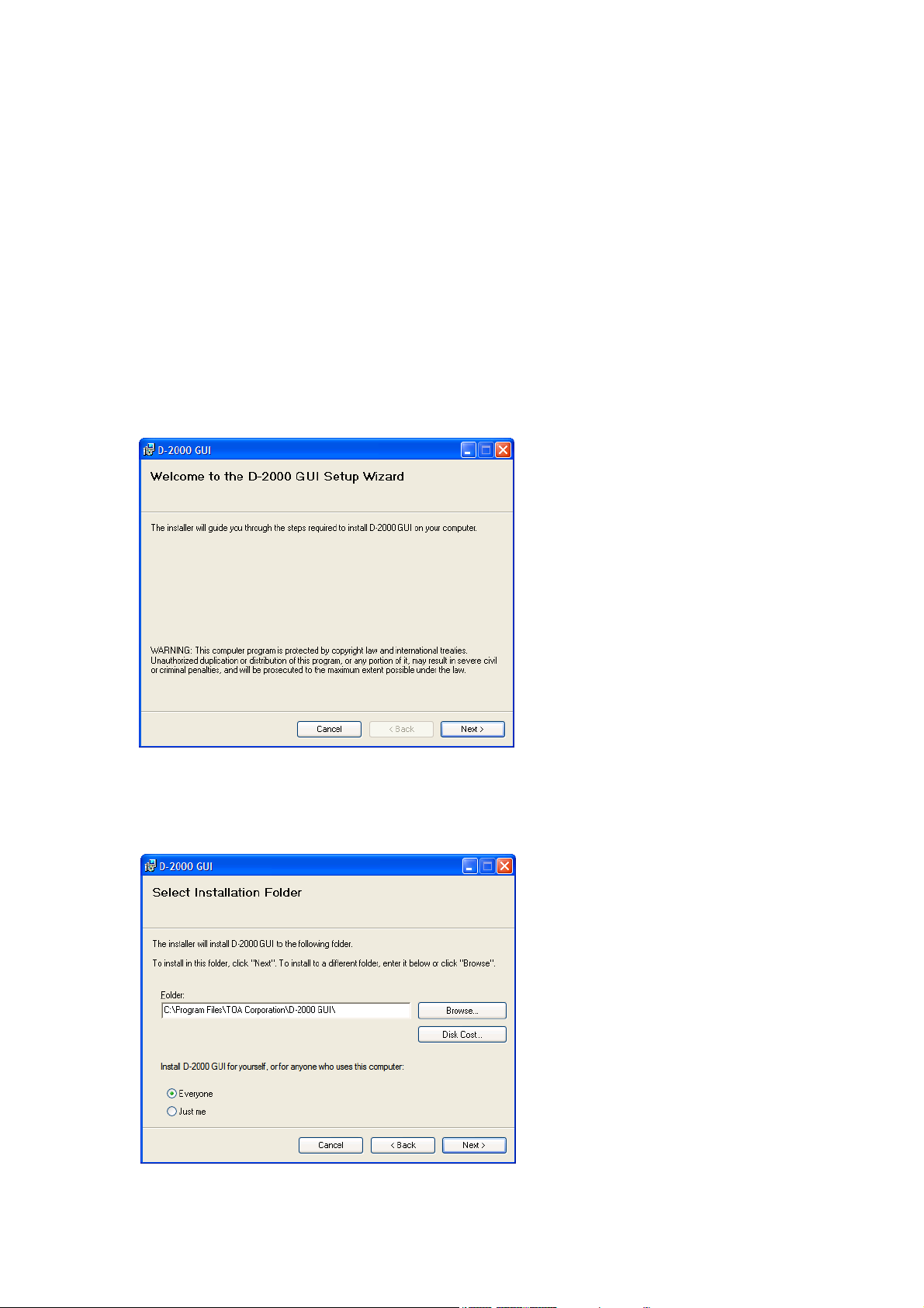
Step 5. Double-click the "setup.exe."
The following window is displayed.
Step 6. Check the contents of the window, then click the "Next" button.
The following window is displayed.
Page 8
8
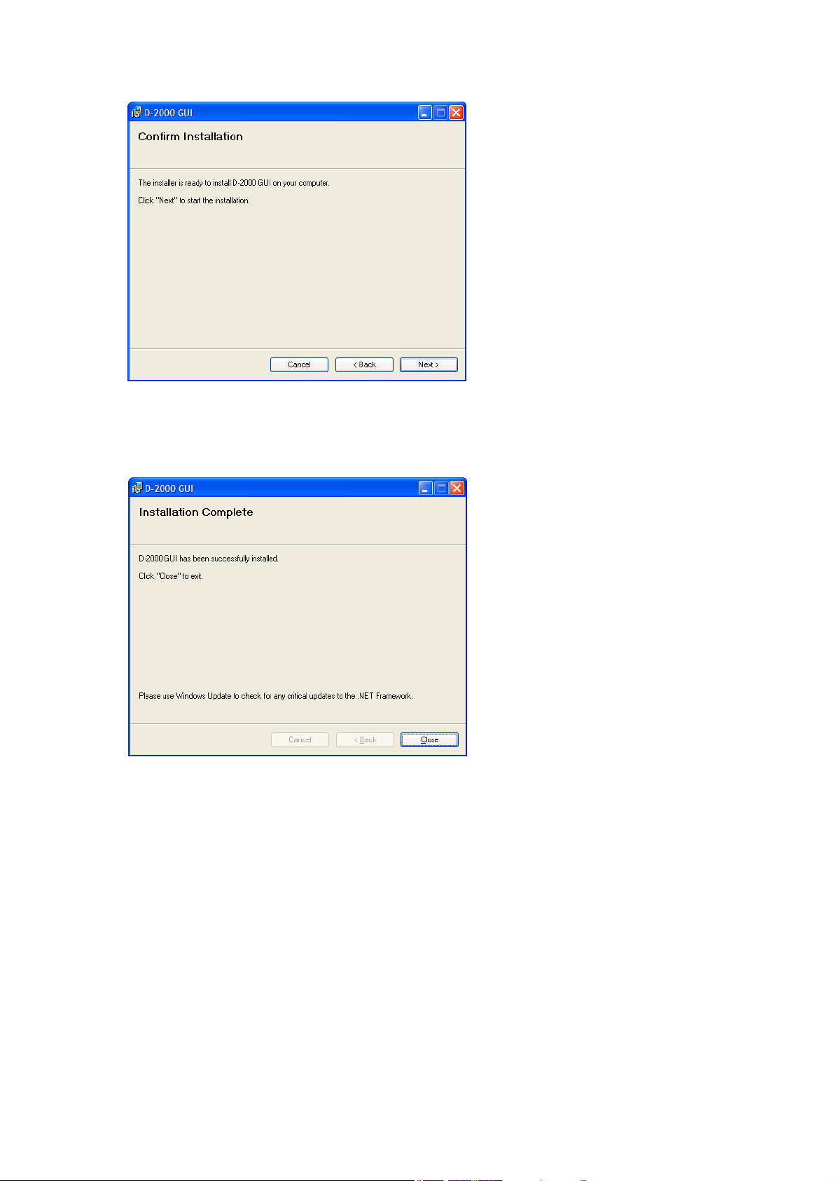
Step 8. Start installation according to the instructions on the screen.
Note
If the .NET Framework is not installed in the PC, follow the on-screen instructions to install it.
Step 9. Click the "Close" button after installation completion.
The shortcut icon for the D-2000 GUI executable program is stored in the PC's start menu.
Step 7. If necessary, change the folder into which the software will be installed, then click the "Next" button.
The following window is displayed.
Page 9

9
2.2. Uninstalling the D-2000 Setting Software
Step 1. Click the Start button on the PC's desktop, and select "Setting Control Panel."
Step 2. Double-click the following icon.
• Windows Vista and Windows 7: "Programs and Features"
• Windows XP: "Add or Remove Programs"
The currently installed program will then be displayed.
Step 3. Select "D-2000 GUI."
Step 4. Click the following button to uninstall the software.
• Windows Vista and Windows 7: "Uninstall"
• Windows XP: "Delete"
Page 10
10
3. STARTING THE SOFTWARE
The following two different methods are available for starting the installed D-2000 Setting Software:
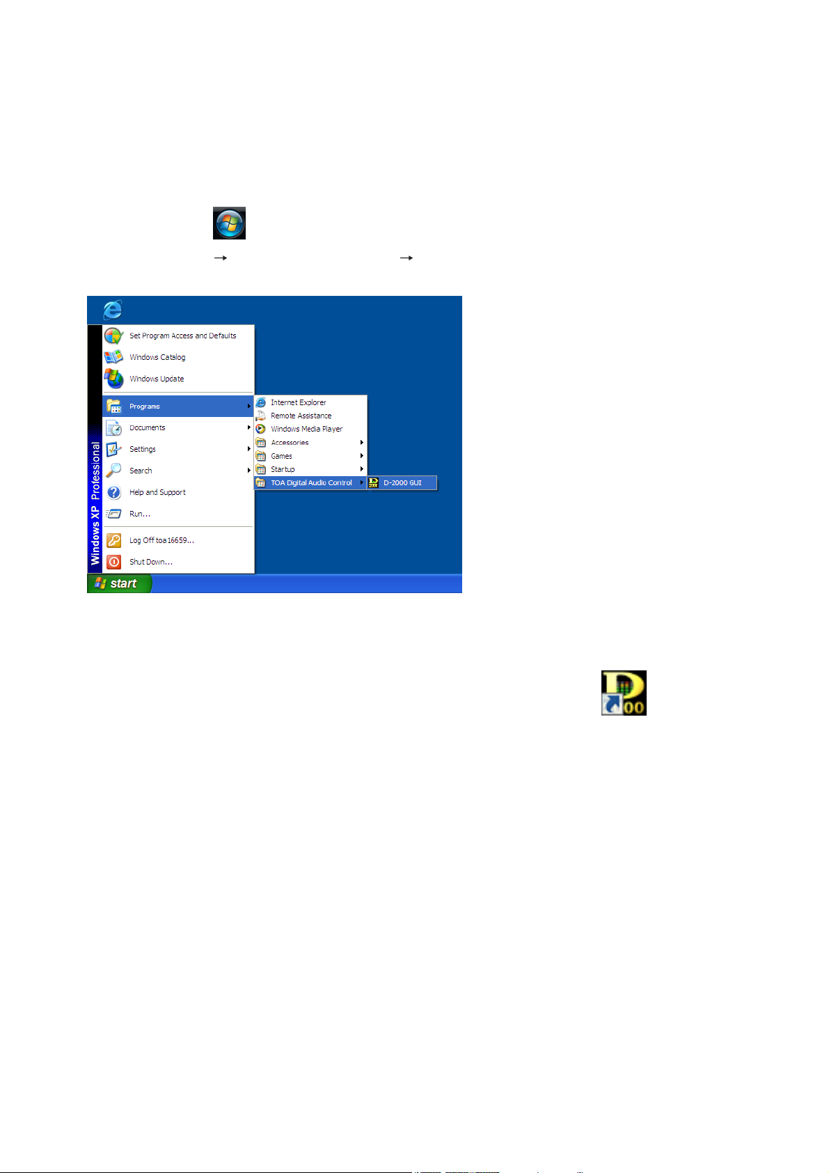
(1) Starting from the "Start" menu
You can start the D-2000 Setting Software from the start menu.
Click the Start button on the PC's desktop,
and select "Programs TOA Digital Audio Control D-2000 GUI" to start.
(2) Starting from the shortcut icon
You can start the D-2000 Setting Software by double-clicking the shortcut icon created on the
desktop after installation completion.
Page 11
11
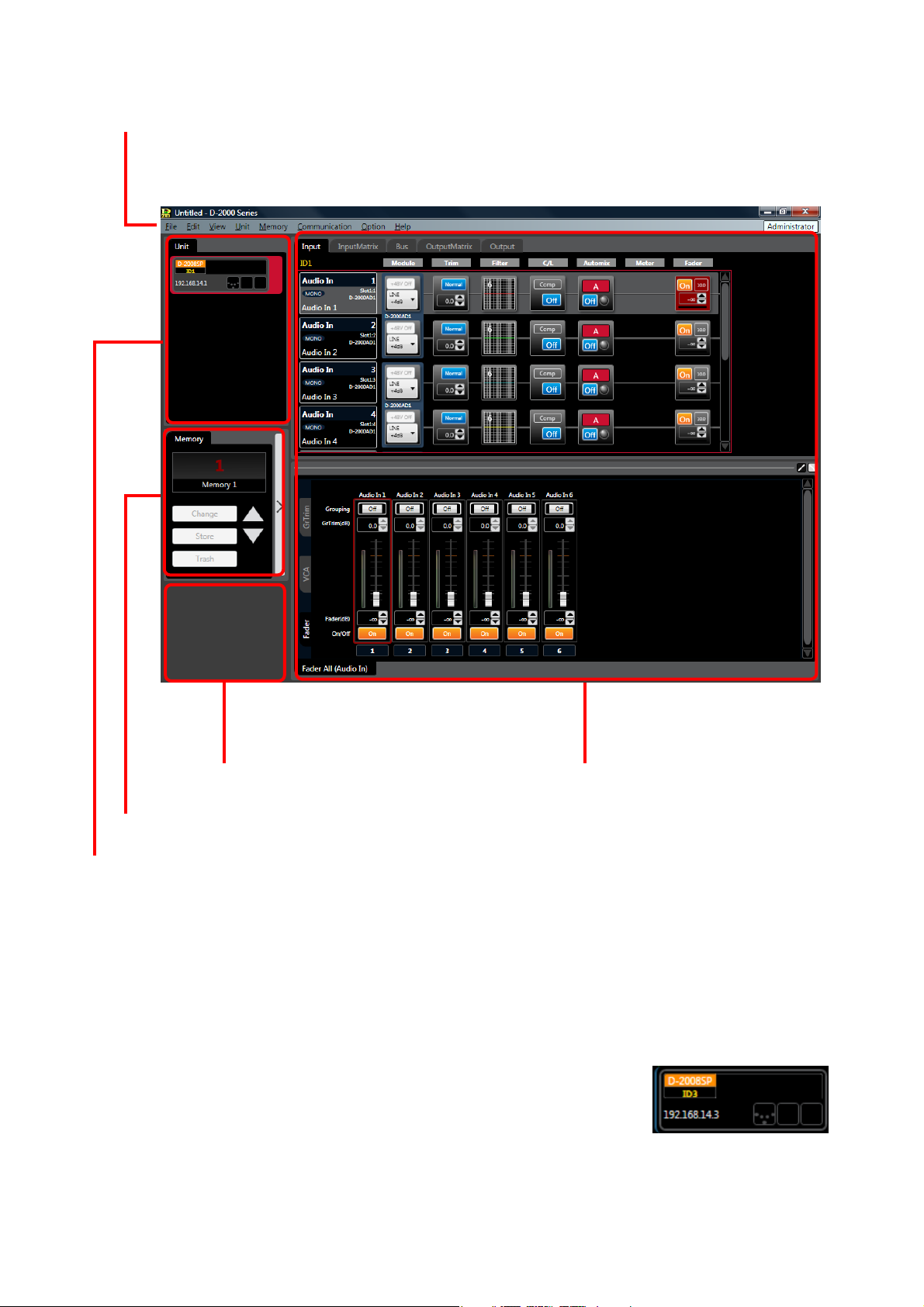
4. MAIN SCREEN AND MENU ITEM DESCRIPTION
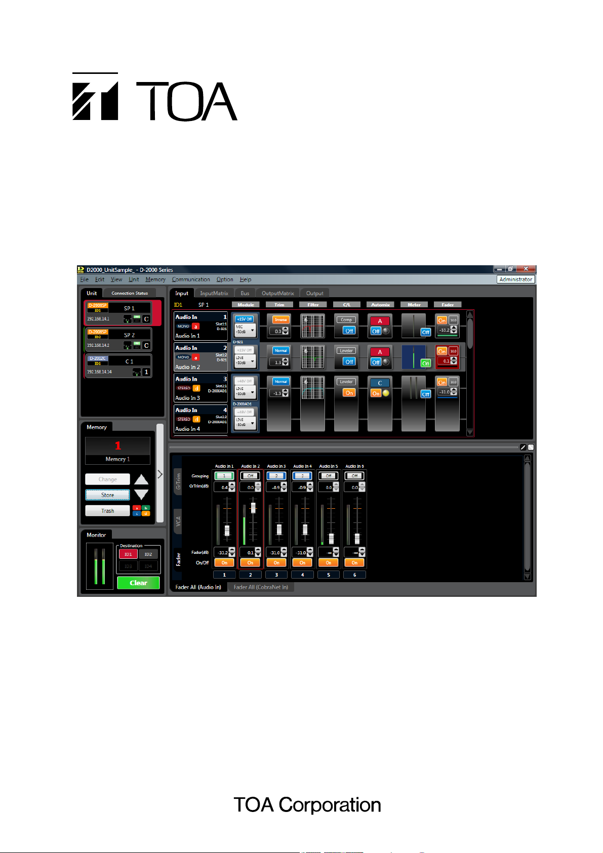
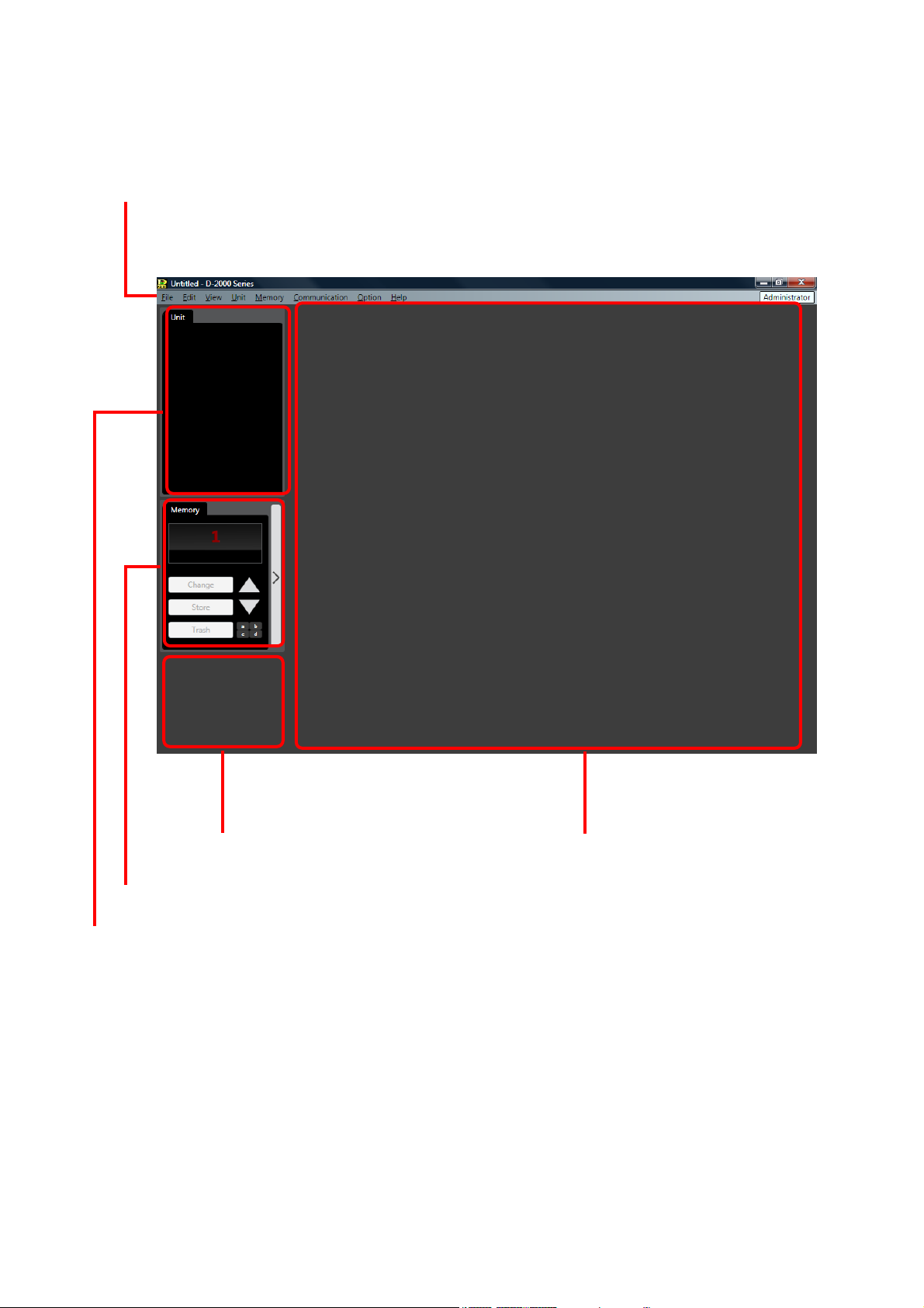
4.1. Main Screen
Starting the D-2000 Setting Software causes the main screen to appear.
Menu (See the next page.)
Unit view (See p. 29.), Connection status view (See p. 30.)
Memory view (See p. 31.)
Main view (See p. 38 and 106.)
Monitor view (See p. 33.)
Page 12

12
4.2. Menu Item Description
4.2.1. File
New: Creates (sets) a new data file.
Open... : Calls up the existing data file.
Note
The following logon screen may be displayed.
This screen appears when a user level is set.
(Refer to p. 124, "Logging on when the user level is enabled.")
Save: Overwrites the file being edited.
Save As... : Saves the file being edited under a different name.
Exit: Exits the D-2000 Setting Software.
Import: Imports (loads) only the information on the D-2008SP with ID1 out of the
existing data files, and adds it into the file being edited.
Note
It is not possible to import the information on the D-2012C and the one on
the D-2008SP other than that with ID1.
4.2.2. Edit
Copy: Copies the value set for the function box selected on the flow view (see
p. 38) to the clipboard.
Paste: Pastes the data in clipboard to the function box selected on the flow view.
Initial value: Initializes the value set for the function box selected on the flow view.
Box Write Protect...
Off: Sets no restriction on write to box.
Low: Restricts the operator from changing the parameters set in the box.
Mid: Restricts the operator from changing all settings in the box.
High: Restricts the administrator from changing the parameters set in the box,
and the operator from changing all settings in the box.
4.2.3. View
Contents View...
Show/Hide: Shows or hides the contents view. (See p. 46.)
Floating: Floats the contents view window.
Docking: Docks the contents view window.
Level Monitor View...
Show/Hide: Shows or hides the level monitor view. (See p. 34.)
Floating: Floats the level monitor view window.
Docking: Docks the level monitor view window.
Split: Displays the different level areas in a single D-2008SP one above the
other.
All Mute View...
Show/Hide: Shows or hides the all mute view. (See p. 36.)
All Mute: Turns on or off the all mute function.
Routing Monitor View...
Show/Hide: Shows or hides the routing monitor view. (See p. 37.)
Page 13

13
4.2.4. Unit
Create New Unit... : Creates a new unit. (See p. 15 and p. 24.)
Delete Unit... : Deletes the unit from the setting data. (See p. 25.)
Change Unit Configuration... : Changes the unit's input/output configuration. (See p. 25.)
Slot Information... Lists the module configuration stored in the unit and the cognitive
information of the slot-mounted modules. (See p. 26.)
Names... : Changes the names of the unit and its inputs and outputs. (See p. 27.)
4.2.5. Memory
Change
Memory (1 – 32): Recalls one out of 32 preset memories. (See p. 149.)
Store
Memory (1 – 32): Writes setting contents in one of 32 memories. (See p. 149.)
Memory Setting: Performs the following settings concerning the preset memory.
(See p. 150.)
• Name setting
• Cross fade Time
• Fader Layer Recall
Power ON
Last Memory/Memory (1 – 32): Select the preset memory to be recalled when the unit's power is turned
on from the Last Memory or 32 memories.
If you select the Last Memory, the unit starts with the last recalled preset
number before turning off the power.
Note
When the Change Safe function (see p. 126) is used, "Last Memory" or
any preset memory to which the Change Safe group or groups have been
assigned cannot be set for the Power On Memory function.
4.2.6. Communication
Connect... : Connects the unit to a PC for online processing. (See p. 141.)
Disconnect... : Disconnects the unit from a PC for offline processing. (See p. 148.)
Note
The unit's setting does not change while in the offline state even if it is
changed with a PC.
Bulk Transmission... : Transmits data of the currently opened file to the unit. (See p. 141.)
Bulk Receiving... : Receives the unit's data. (See p. 141.)
Auto Connection: Makes an automatic connection when the file is opened next time.
Firmware: Displays the unit's firmware version number. (Only valid when connected
online)
Comm Setting... : Allows you to perform network settings and to designate the unit's IP
address to which this software can access. (See p. 131.)
Page 14

14
4.2.7. Option
Security Settings: Set the user level and the restriction of operations. (See p. 123.)
Change Safe Setting: Performs the Change Safe function while offline. (See p. 126.)
Console SEL/MONI Link Setting: Performs the console SEL/MONI interlock setting. (See p. 129.)
Contact Input Setting... : Sets the contact inputs of the D-981 or D-983 Remote Control Module, or
the D-984VC VCA Control Module. (See p. 85.)
Contact Output Setting... : Sets the contact outputs of the D-981, D-983, or the D-984VC.
(See p. 91.)
VCA Module Setting... : Sets fader assignments for the D-984VC VCA Control Module.
(See p. 97.)
CobraNet Module Setting
CobraNet Bundle Setting: Sets the Cobranet bundle number for the selected unit. (See p. 101.)
CobraNet Bundle Matrix Setting: Sets the Cobranet bundle number in matrix format when 2 or more
D-2008SPs (max. 4 units) are Cobranet-connected to each other.
(See p. 103.)
Wordclock Setting... : Selects the synchronization for the word clock. (See p. 104.)
External Control Port Setting... : Sets interface communication speed with such external control equipment
as the AMX. (See p. 105.)
Fader Layer Change
Layer (1 – 4): Recalls the D-2012C's fader layer. Layers not assigned to D-2012C's
function keys cannot be recalled. (See p. 122.)
Power On Fader Layer
Last Layer/Layer (1 – 4): Selects the fader layer to be recalled when the D-2012C's power is
switched on. Selection is made from either the Last Layer or Layers 1 – 4.
Layers that have not been assigned to the D-2012C's function keys
cannot be selected. Selecting Last Layer causes the D-2012C to start with
the layer number recalled just before the power was switched off. (See p.
122.)
Note
This setting is valid only when the Fader Layer Recall function is set to
"None." (See p. 122.)
Console Setting: Performs the channel setting of the D-2012C Remote Console Unit.
(See p. 119.)
4.2.8. Help
About... : Displays the D-2000 Setting Software version number.
Page 15
15
5. UNIT CONFIGURATION AND SYSTEM-RELATED SETTINGS
5.1. D-2008SP Configuration Settings
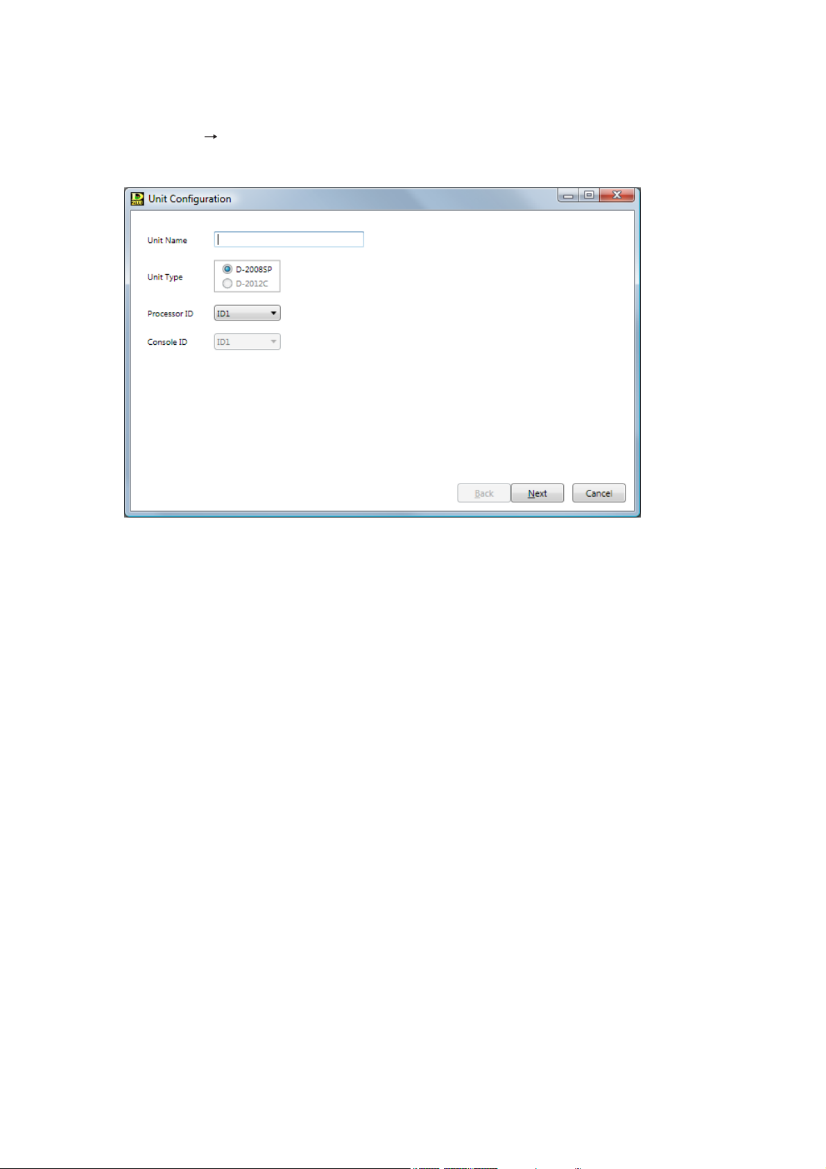
Step 1. Select "Unit Create New Unit..." from the menu.
The Unit Configuration setting screen is displayed.
Step 2. Enter a unit name.
Up to 20 alphanumeric characters can be used.
Step 3. Set Unit Type.
Select the D-2008SP as the Unit type to be created.
Step 4. Set the Processor ID number by selecting it from the Combo box. (Setting range: ID1 – ID4)
Page 16
16
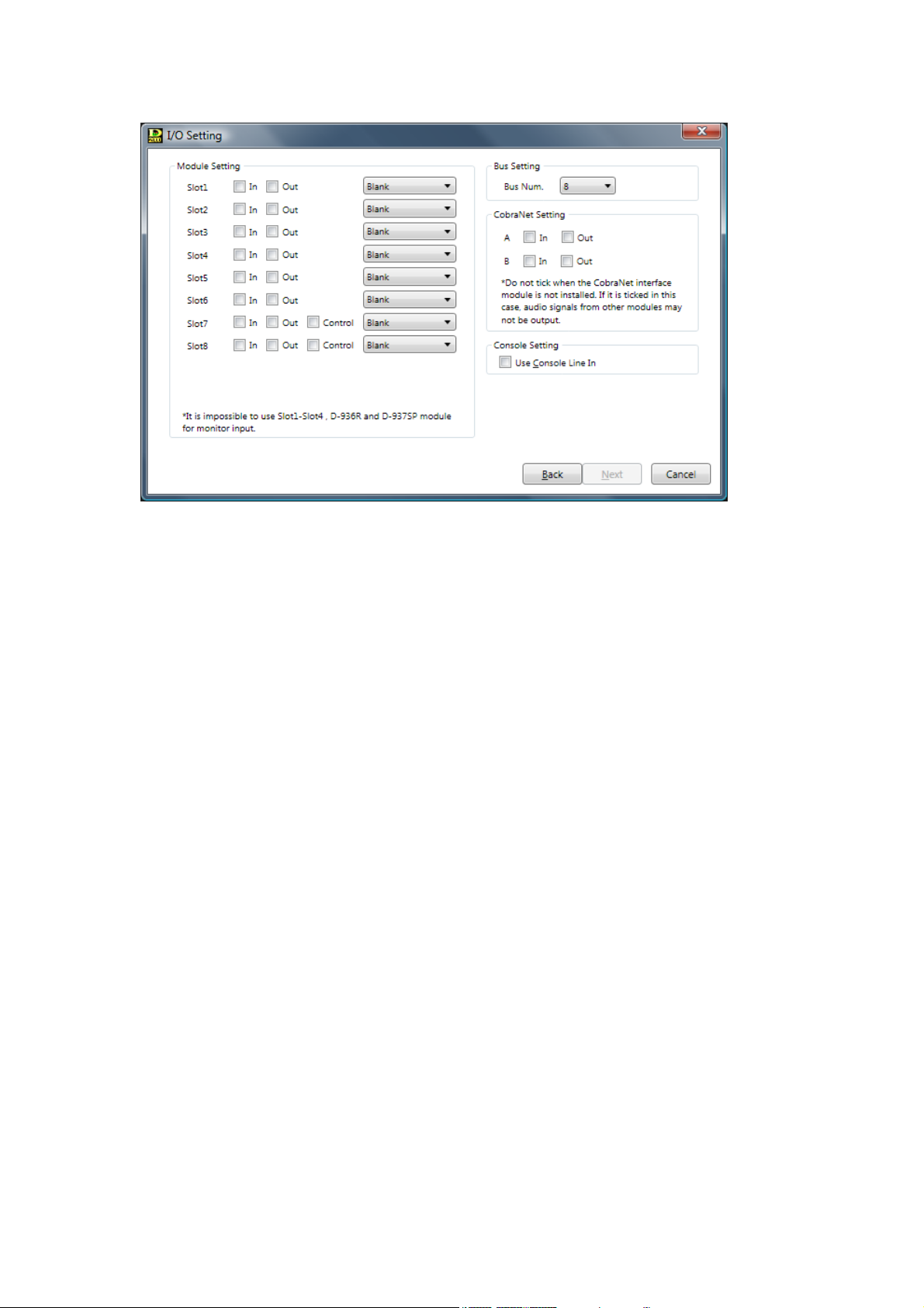
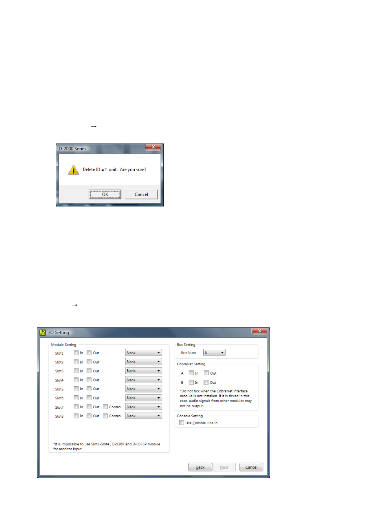
Step 5. Click the "Next" button.
The I/O Setting screen is displayed.
Step 6. Perform Module, Bus, CobraNet, and Console Settings.
Notes
• CobraNet is a trademark of Cirrus Logic, Inc.
• The unit having only inputs or outputs cannot be created.
6-1. Module Setting
Select the type of module (input, output, and control) by clicking the appropriate checkbox for each
slot and select the modules to be used from the Combo box.
• For Slots 1 – 6, input modules and output modules can be selected.
• For Slots 7 and 8, input modules, output modules, and control modules can be selected.
The Combo box's content changes depending on the content selected in the checkbox.
Note
Signals of the input and output modules are separately processed by 2 DSP devices, each of which
handles the modules in determined slot numbers as follows.
• DSP #1: Modules in Slot 1 – Slot 4
• DSP #2: Modules in Slot 5 – Slot 8
As the available filter number for input and output channels is limited by the DSP in charge, design in
which slots modules are installed making the filter number as equal as possible for 2 abovementioned slot groups. (See p. 21, Filter Point Number Setting Screen.)
6-2. Bus Setting
Select the number of buses to be used from the Combo box. (Default setting: "8")
6-3. CobraNet Setting
Click the input or output checkbox for A or B channel.
Note
Do not tick the CobraNet Setting item when the CobraNet interface module is not installed.
If it is ticked in this case, audio signals from other modules may not be output.
6-4. Console Setting
Click the checkbox when using the D-2012C's line input terminal. The D-2008SP's monitor bus
terminal must be connected to the D-2012C's monitor bus terminal. (For details, please read the
separate installation manual.)
Page 17
17
Step 7. Click the "Next" button.
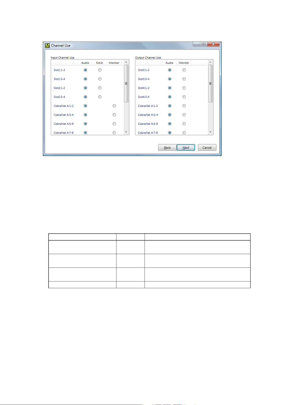
The Channel Use screen is displayed.
Step 8. Set Channel Usage.
8-1. Input Channel Use Settings
Select the use to be assigned to each module slot in 2-channel units from "Audio," "Ext.In*," or
"Monitor."
* "Ext. In" is the external input used for direct input to the output matrix. Refer to the block diagrams
included in the separate installation manual.
Notes
• Slot 1 – Slot 4 cannot be used for "Monitor."
• The input modules used for "Monitor" are subject to the restrictions listed below.
8-2. Output Channel Use Settings
Select the use to be assigned to each module slot in 2-channel units.
It can be selected in "Audio."
"Monitor" can be set to each D-2008SP's ID number from 4 monitor channels. (See p. 19.)
When the channel to be monitored is selected on the D-2000 Setting Software or D-2012C, audio on
the corresponding channel of this unit is output.
Input module Availability Restriction
D-2000AD1, D-921F, D-921E
D-923F, D-922E
D-923AE
D-936R, D-937SP
Usable
Usable
Usable
Not usable
"Phantom power" is fixed to "OFF," and "Input
sensitivity" to "+4 dB."
Set "Phantom power" to "OFF," and "Input
sensitivity" to "+4 dB" using the DIP switch.
The setting status cannot be displayed on the
D-2000 Setting Software.
Not usable
Page 18
18
Step 9. Click the "Next" button.
• Checking the input checkbox in "CobraNet Setting" on the I/O Setting screen causes the CobraNet
Channel Use screen to be displayed. (Advance to Step 10.)
• If the input checkbox remains unchecked in "CobraNet Setting" on the I/O Setting screen, the
channel setting screen (same screen as in Step 11) is displayed. (Advance to Step 12 on the next
page.)
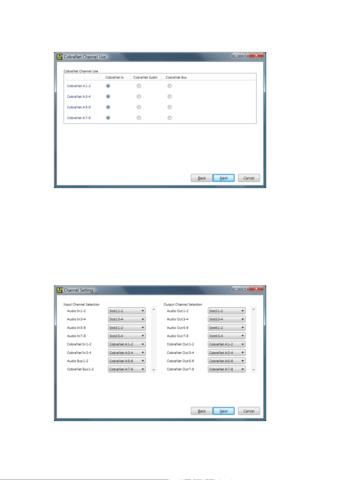
Step 10. Set the CobraNet Channel Use Settings.
Select the use for each CobraNet channel in 2-channel units.
Select from "CobraNet In," "CobraNet Sub In," or "CobraNet Bus."
Step 11. Click the "Next" button.
The Channel Setting screen is displayed.
Page 19
19
Step 12. Perform Input and Output Channel Selection.
12-1. Input Channel Selection
• Select the modular slot channels to be assigned to each input channel in 2-channel units.
• Select the CobraNet channels to be assigned to each input channel in 2-channel units.
12-2. Output Channel Selection
• Select the modular slot channels to be assigned to each output channel in 2-channel units.
• Select the CobraNet channels to be assigned to each output channel in 2-channel units.
Step 13. Click the "Next" button.
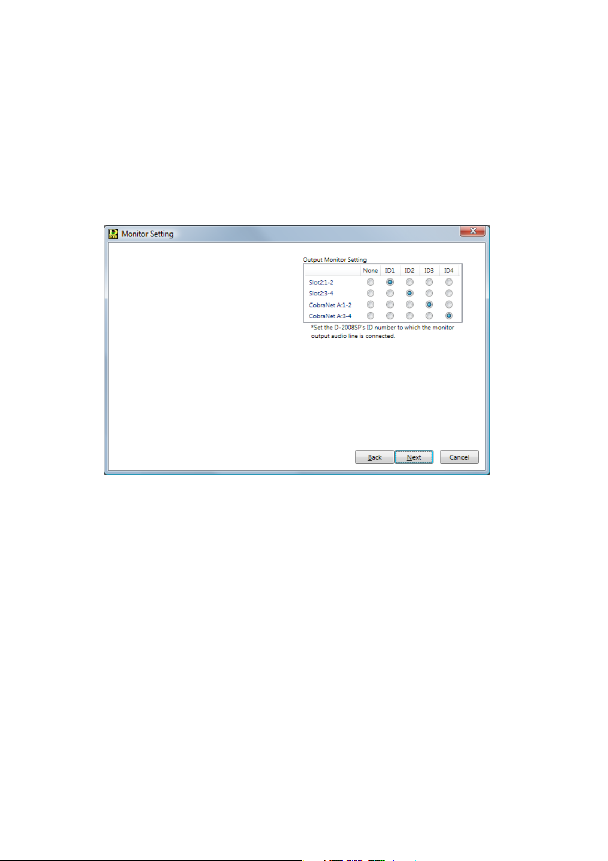
• When "Monitor" is selected on the Channel Use screen, the Monitor Setting screen is displayed.
(Advance to Step 14.)
• When “Monitor” is not selected on the Channel Use screen, the Stereo Link Configuration screen
(same screen as in Step 15 on the next page) is displayed. (Advance to Step 16 on the next
page.)
Step 14. Perform Monitor setting.
In the Output Monitor Setting section, set the D-2008SP's ID number to which the monitor output
audio line is connected.
Note
There is no item to be set for the input monitor.
Page 20
20
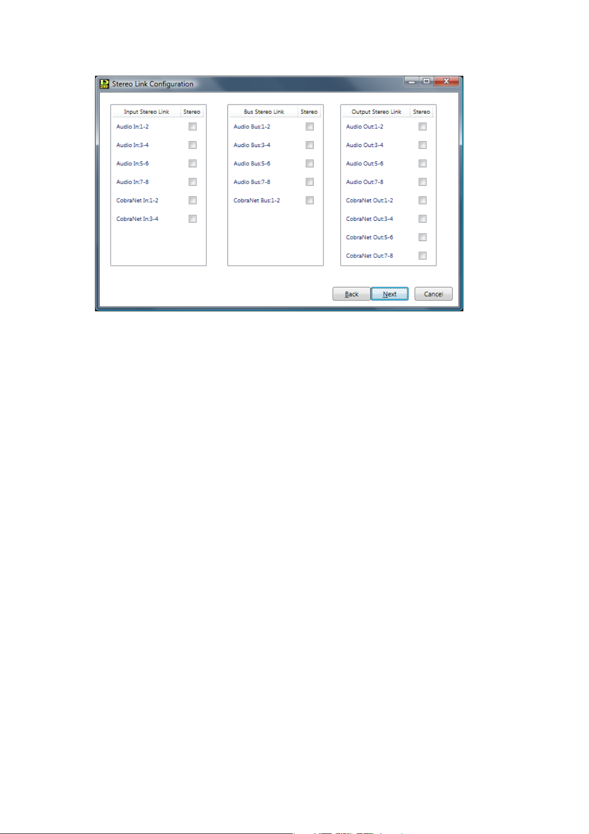
Step 16. Perform Stereo Link Configuration settings.
Checking the checkbox of a channel allows stereo link settings for that channel in 2-channel units.
[Stereo link functions]
• Performing Stereo Link settings for adjoining channels (such as Channels 1 and 2, 3 and 4, and 5
and 6) causes signal processing parameters for Compressor/Auto-Leveler, filter, and other
functions to be linked. If a signal processing parameter for either channel is modified, the
corresponding parameter of the other "linked" channel also simultaneously changes.
• The Stereo Link function can be independently set for input and output sides. Enable the Stereo
Link setting when wishing to make the settings of both left and right channels identical, such as
when a stereo input is received from a CD player or other stereo sound source and stereo output
is sent to a tape recorder or similar stereo equipment.
[Stereo link setting restrictions]
• If you assign the bus from the stereo-linked input channel to the stereo-linked output channel, both
left and right channels are simultaneously assigned. For example, when Input 1 is stereo-linked to
Input 2, and Output 1 is linked to Output 2, if Input 1 is assigned to Output 1, Input 2 is also
similarly assigned to Output 2. However, you cannot assign Input 1 to Output 2 or Input 2 to
Output 1.
• Stereo-Link settings cannot be performed for the output channels that have employed the
crossover function. Conversely, the stereo-linked channels cannot use the crossover function.
• The FBS function cannot be used for the stereo-linked bus channels.
Step 15. Click the "Next" button.
The Stereo Link Configuration screen is displayed.
Page 21
21
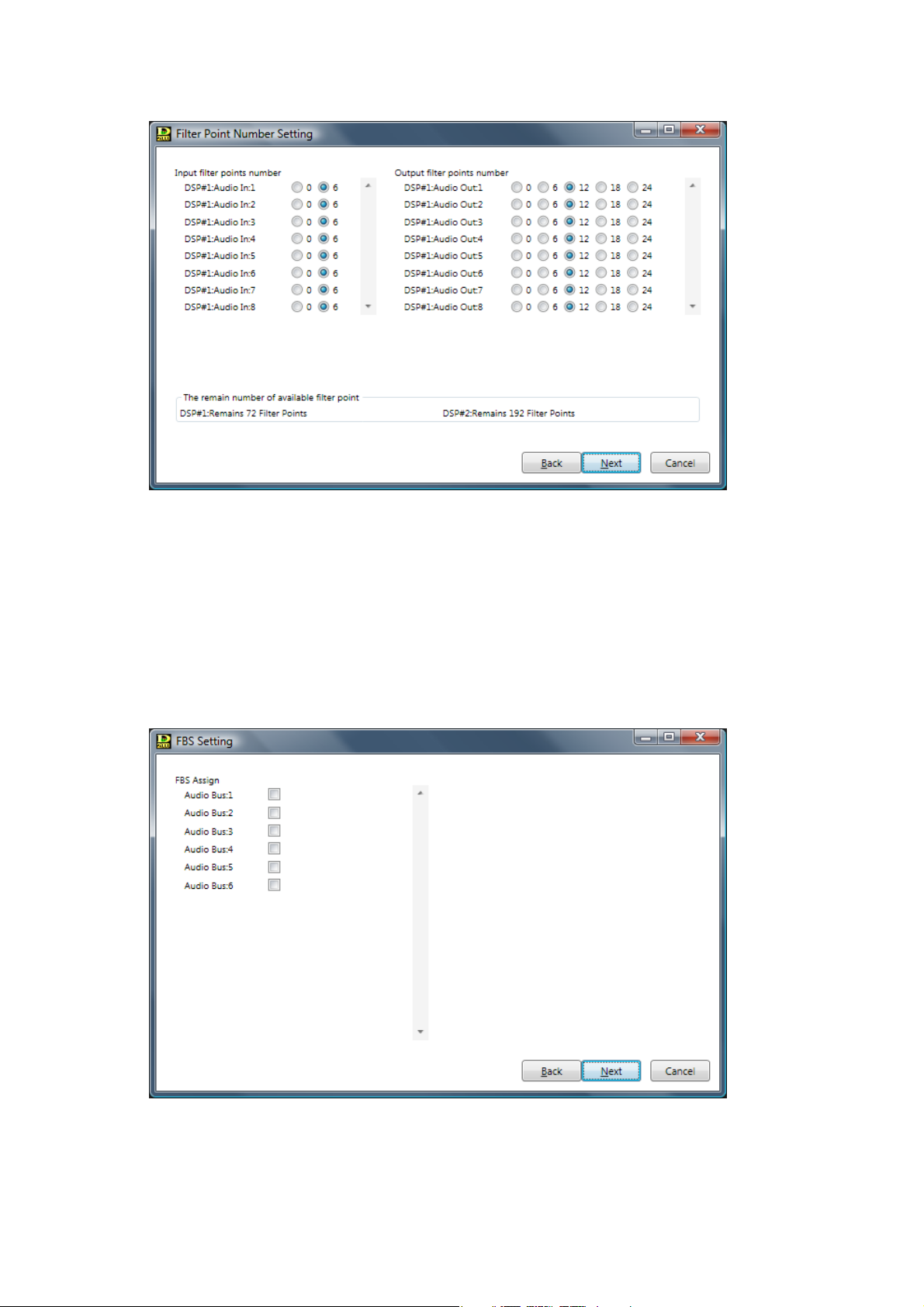
Step 17. Click the "Next" button.
The Filter Point Number Setting screen is displayed.
Step 18. Perform Filter Point Number Setting.
Set the number of filters to be used for individual input and output channels.
Note
The number of available filters is limited. Confirm the available filter number on the screen.
When more filters are needed, changing module mounting slots may solve this problem. (Refer to
p. 16, "6-1. Module Setting.")
Step 19. Click the "Next" button.
The FBS Setting screen is displayed.
Step 20. Perform FBS Setting.
Select bus channels for FBS (Feedback Suppressor) assignment. Up to 4 channels can be
assigned.
Page 22
22
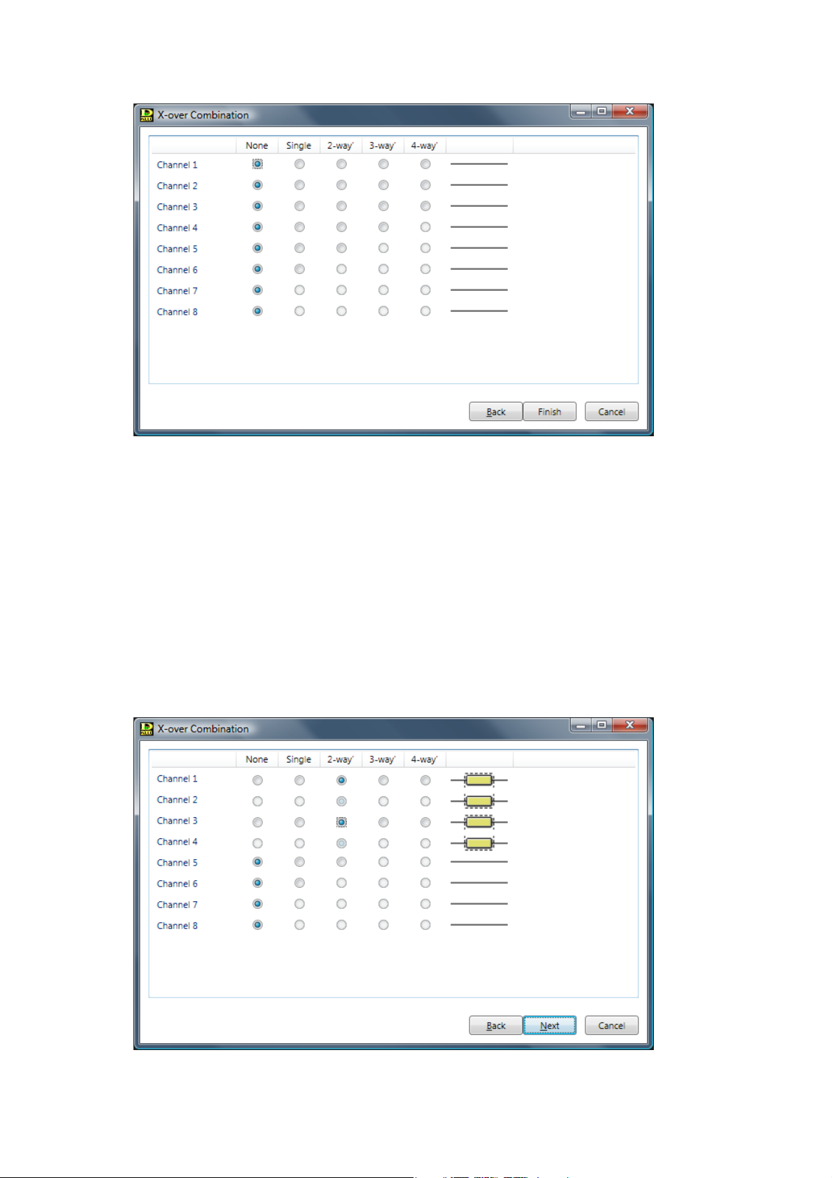
Step 21. Click the "Next" button.
The X-over Combination screen is displayed.
Note
To set the crossover function, proceed to Step 22. Otherwise, proceed to Step 25 on the next page.
Step 22. Click the setting contents to perform the crossover combination settings.
Setting status is displayed on the right side of the screen.
When "2-way" is selected on a channel, its next channel is used together.
When "3-way" is selected on a channel, its next 2 channels are used together.
When "4-way" is selected on a channel, its next 3 channels are used together.
Note
Performing the crossover combination settings causes 1 or 2 output filter points on the
corresponding channel to be used: 1 filter point is used when HPF or LPF is set, and 2 filter points
when BPF (both HPF and LPF) is set.
[2-way/2-channel setting example]
Page 23
23
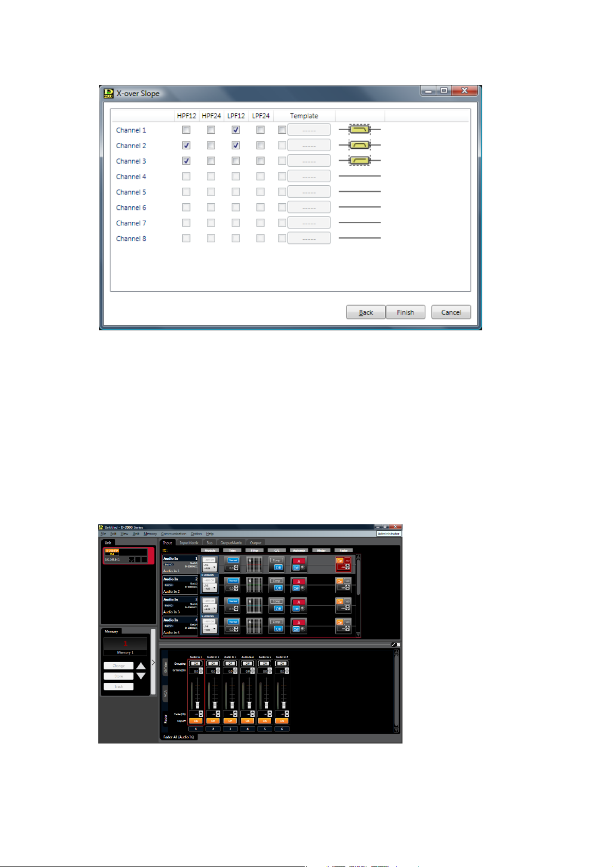
Step 23. Click the "Next" button.
The X-over Slope screen is displayed.
Step 24. Tick the checkboxes for the crossover slope settings.
Setting status is displayed on the right side of the screen.
Note
The template created using the setting software for the D-901 Digital Mixer can be used.
When using the template, tick "Template" check box, then the button located on the right side of a
checkbox becomes active. Click this button, and a dialog box for selecting the file is then displayed.
If you select the file and click the "Finish" button, the signal flow (see below) is displayed.
Step 25. Check to ensure that the setting is correct and click the "Finish" button.
The signal flow is displayed.
Page 24

24
5.2. D-2012C Configuration Settings
Step 1. Select "Unit Create New Unit..." from the menu.
The Unit Configuration setting screen is displayed.
Step 2. Enter a unit name.
Up to 20 alphanumeric characters can be used.
Step 3. Set Unit Type.
Select the D-2012C Remote Console Unit as the Unit type to be created.
Step 4. Set the Console ID number by selecting it from the Combo box. (Setting range: ID1 – ID4)
Step 5. Click the "Finish" button.
The Console view is displayed.
Page 25
25
5.3. Unit Change or Deletion and Slot Information Confirmation
5.3.1. Deleting the unit
The unit that has been already created can be deleted only when the PC is not in communication with the unit.
Notes
• Deleting all the D-2008SP units when both the D-2008SP and D-2012C units have already been created
simultaneously deletes the D-2012C as well.
• Deleting the D-2008SP with ID1 disables the interlock function to control other units within the system, and
the control (see p. 84 and 109) by pressing the D-2012C's function key as well.
Step 1. Select "Unit Delete Unit..." from the menu.
The confirmation screen is displayed.
Step 2. Click the "OK" button.
The unit is deleted.
5.3.2. Changing the unit configurations
The unit configuration that has been already created can be changed only when the PC is not in
communication with the unit.
Select "Unit Change Unit Configuration..." from the menu to display the I/O Setting screen. Unit
configuration can be changed in the same procedures as for creating a new unit configuration.
Note: The unit selected in the unit view (see p. 29) can be
subject to deletion.
Page 26
26
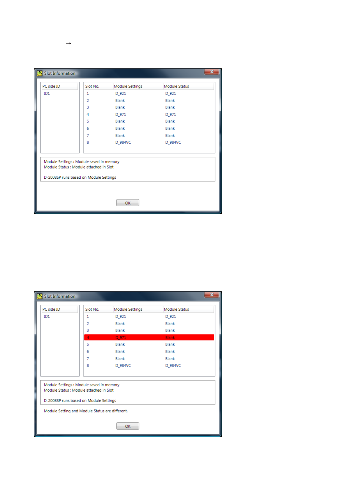
5.3.3. Confirming the slot information
Select "Unit Slot Information..." from the menu to display the Slot Information screen.
The screen offers information on the module settings and the module status while the PC is in communication
with the unit.
• PC side ID: Unit ID of the setting data on the PC
• Slot No.: Slot number of the module on the unit's rear panel
• Module Settings: Model of module stored in memory
• Module Status: Model of module inserted in unit
If the Module settings and Module status information on a slot do not match, the slot data is highlighted in red
as shown below.
Note
Unless the Module settings and Module status information on all slots exactly match with each other, the unit
does not operate correctly.
(For procedure, please refer to the next page.)
Page 27
27
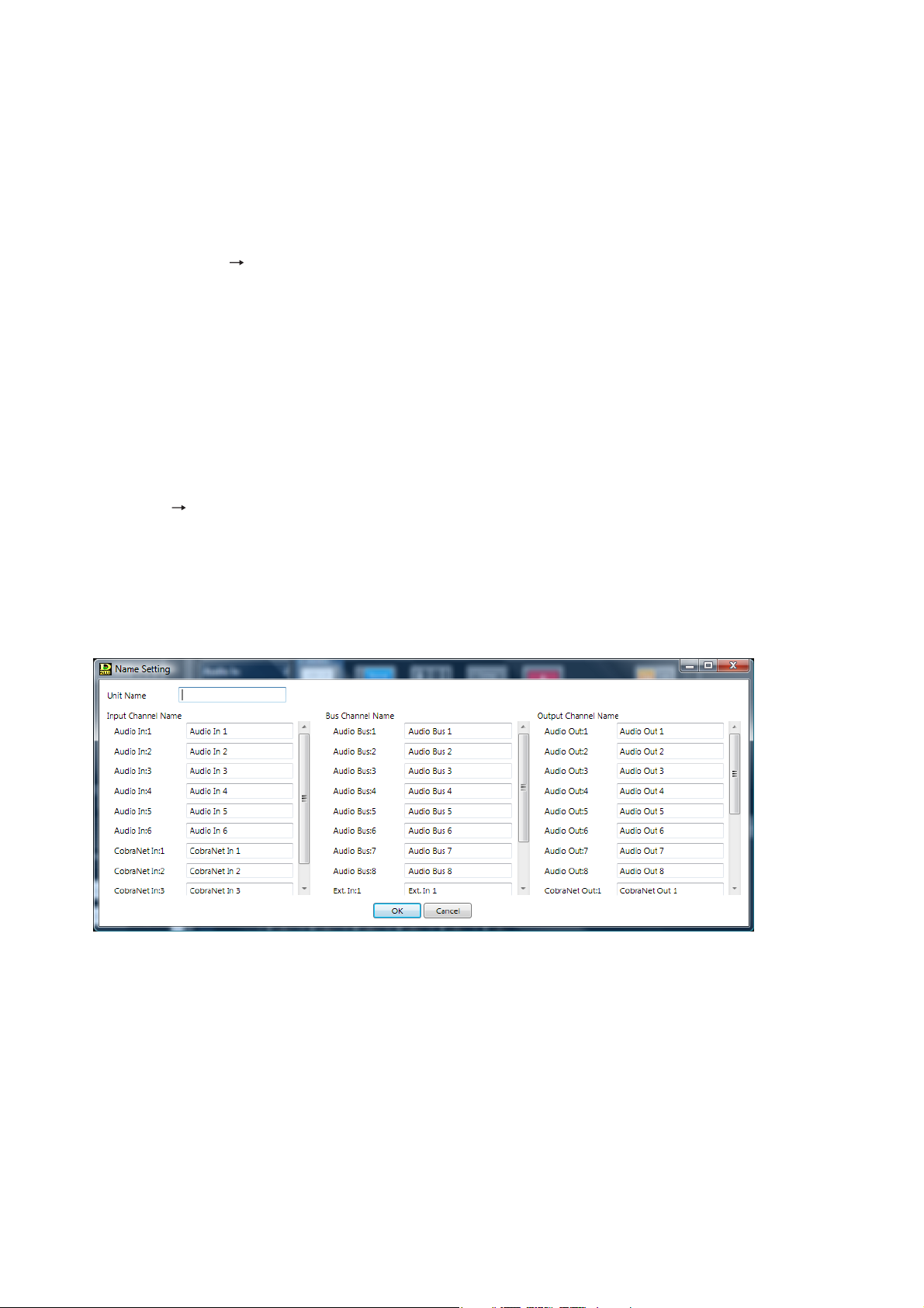
5.3.4. Changing the unit names
Select "Unit Names..." from the menu to display the Name Setting screen.
The Unit's name and Input/Output/Bus channel's names can be changed.
Notes
• Up to 20 alphanumeric characters can be used.
• To make the unit name blank, enter a space with the space key.
Deleting the default name cannot set it blank. (The default name remains as it is.)
[Operating the unit according to the Module settings information]
Reinstall modules into the unit according to the module settings information.
[Operating the unit according to the Module status information]
Change the Module settings information according to the following procedures.
Step 1. Reset the Unit configuration setting on the software when the PC is not in communication with the
unit.
Select the unit for which you want to change the input/output configuration in the unit view.
Select "Unit Change Unit Configuration..." from the menu to display the Unit Configuration setting
screen. In the same procedures as for creating a new Unit configuration, set the module configuration.
(See p. 16.)
Step 2. Execute the bulk transmission or make communication connections with the unit by designating the
transfer direction "PC to Unit" for all data items. (See p. 145.)
Page 28
28
6. MAIN SCREEN AFTER COMPLETION OF UNIT CONFIGURATION
Menu (See p. 12.)
Main view (See p. 38 and 106.)
Unit view (See p. 29.), Connection status view (See p. 30.)
Memory view (See p. 31.)
Monitor view* (See p. 33.)
* Monitor view is displayed only when in online mode.
Please refer to p. 130 regarding putting the unit in online mode (when a PC is in communication with the
unit).
Note
If communications error occurs between the D-2008SP and PC when bulk
receiving (see p. 144) is executed, the monitor view screen will change as shown
at right.
In such cases, initialize the setup data, or execute the bulk reception again after
checking to see if all the units are connected correctly.
Page 29
29
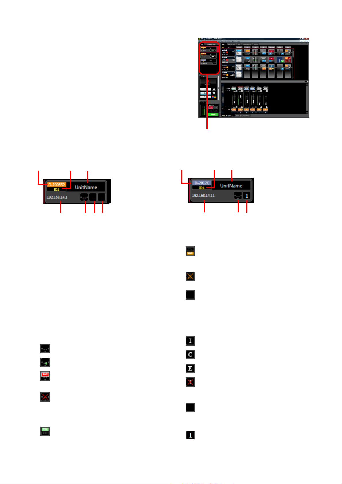
6.1. Unit View
The Unit View is located at the upper left of the main screen.
Performing equipment configuration and system-related
settings displays all units that make up the system.
Selecting the unit display in the unit view switches the unit to
be displayed in the main view.
The unit is displayed in different color depending on its ID
number.
Unit view
(1) (2) (3)
(4) (5) (6) (7)
(1) (2) (3)
(4) (5) (8)
[D-2008SP] [D-2012C]
(1) Unit type
Displays either the D-2008SP or the D-2012C.
(2) Unit ID
Displays the unit’s ID number (ID1 – 4).
(3) Unit name
Displays the unit’s name.
(4) IP address
Displays the unit’s IP address.
(5) Communication connection status
Indicates unit communication connection status.
: Unconnected (offline state)
: Connected (online state)
: Cooling fan failure detected in connected
status (D-2008SP only)
: Communication failure
Confirm network connections.
(6) CobraNet status (D-2008SP only)
: CobraNet PRIMARY LINK
Lights while CobraNet communications are
being performed via the primary port.
: CobraNet SECONDARY LINK
Lights while CobraNet communications are
being performed via the secondary port.
: CobraNet error
Communication failure status
: None
CobraNet module not installed.
(7) Word clock synchronization status
(D-2008SP only)
Indicates word clock synchronization mode.
: Internal synchronization
: CobraNet
: External synchronization
: Failure
(Superimposed over one of the above three
to indicate irregularities.)
: Offline state
(8) Console link group (D-2012C only)
: Displays the console link group number (1 – 4).
(The group number is identical to D2012C's unit ID number.)
Page 30
30
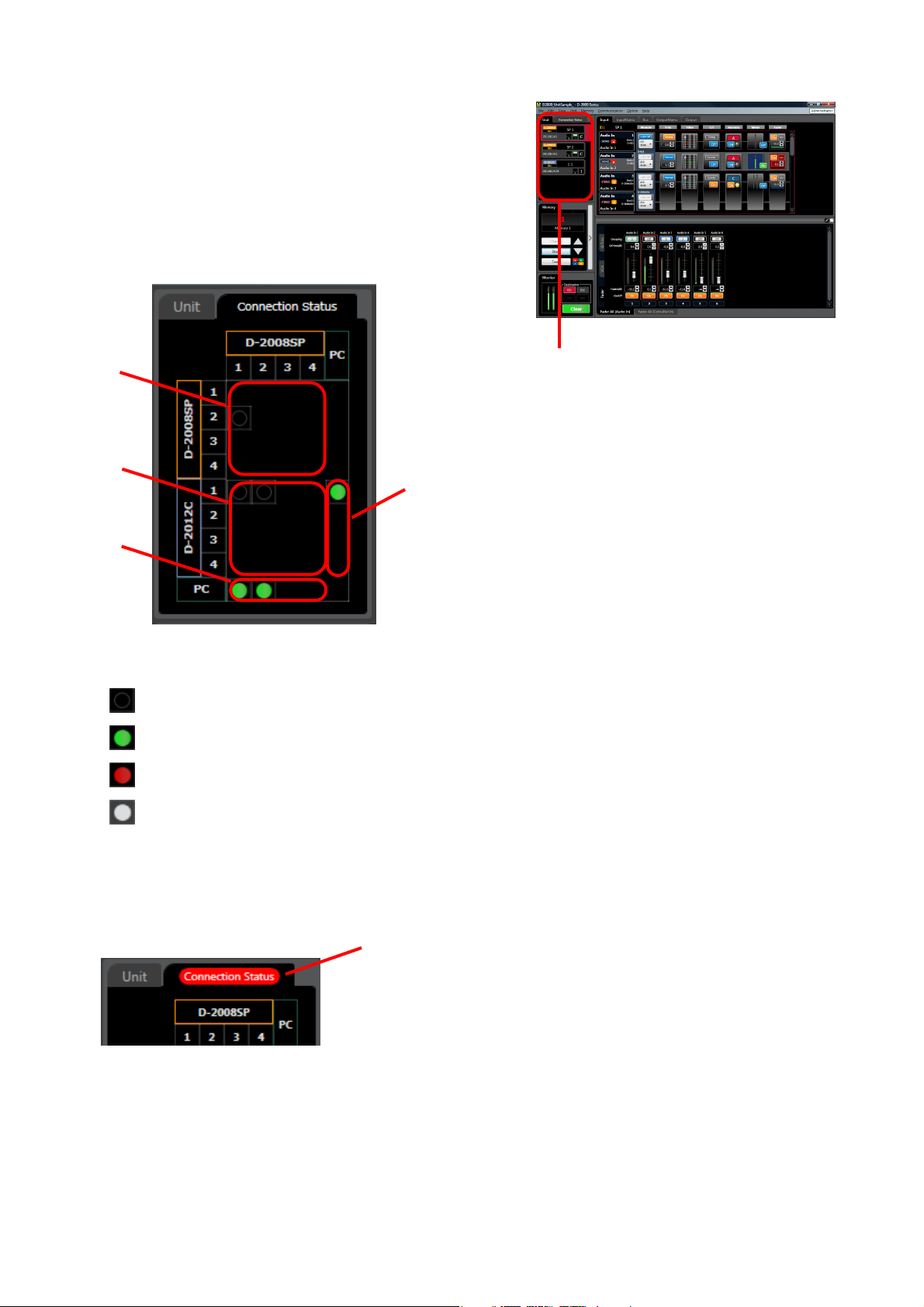
6.2. Connection Status View
Clicking the connection status tab at the upper left of the main
screen at the time of connection displays the connection
status view.
Connection status between the units can be confirmed.
Connection status view
The above view displays the connection status described below at the crosspoint between each unit.
: Unconnected (or not connectable)
: Connected
: Communication error
: Unknown state (Status cannot be obtained due to connection failure between the PC and related
units)
If a communication error occurs on any of the unit, "Connection Status" tab name will be shown in white on
red background.
(4)
(1)
(2)
(3)
(1) Between the D-2008SP and D-2008SP
(2) Between the D-2008SP and D-2012C
(3) Between the D-2008SP and PC
(4) Between the D-2012C and PC
Connection status tab
Page 31

31
6.3. Memory View
The memory view is located at the lower left of the main
screen.
It displays the preset memory (see p. 149) names and the
preset memory numbers being currently selected. It is
possible to recall preset memories and also to write data into
the preset memories.
The panel can be opened or closed by clicking the Memory
List Panel Open/Close button.
When the memory list panel is open, the cross-fade time is
also displayed.
• It displays the preset memory names and the preset memory numbers being currently selected.
• To recall the Preset Memory, use the Up and Down buttons to display the memory number to be changed,
then click the "Change" button.
The menu bar can also be used to recall. (See p. 149, "Recalling the Preset Memory.")
• Editing the recalled Preset Memory enables the "Trash" button display. Clicking the "Trash" button discards
the data in edit and recalls the original data.
• To write data into Preset Memory, use the Up and Down buttons to display the preset memory number to be
stored, then click the "Store" button.
The menu bar can also be used to write. (See p. 149, "Writing Data into the Preset Memory.")
• The Change Safe group indication shows the Change Safe groups to which the selected preset memory
belongs. This indication appears only when the Change Safe function is enabled. (Refer to p. 126.)
Memory view
[Memory list panel closed:]
Change Safe group
indication
Preset memory number
Memory list panel
open/close button
Preset memory name
Store button
Up and down buttons
Change button Trash button
Page 32

32
• The currently selected Preset Memory is displayed in red in the memory list.
• To recall a preset memory, click the corresponding preset memory name in the memory list and click the
"Change" button.
Preset Memory can also be recalled by using the Up and Down buttons to display the preset memory
number or double-clicking the preset memory name to be changed.
The menu bar can also be used to recall. (See p. 149, "Recalling the Preset Memory.")
• Editing the recalled Preset Memory enables the "Trash" button display.
Clicking the "Trash" button discards the data in edit and recalls the original data.
• To write data into the preset memory, click the corresponding preset memory name and click the "Store"
button. The menu bar can also be used to write. (See p. 149, "Writing Data into the Preset Memory.")
• The Change Safe group indication shows the Change Safe groups to which the selected preset memory
belongs. This indication appears only when the Change Safe function is enabled. (Refer to p. 126.)
* For the crossfade time, see p. 150.
Crossfade time*
Up and down
buttons
[Memory list panel open:]
Preset memory number
Currently selected Preset Memory
Preset memory name
Store button
Memory list
Change Safe group indicationChange button
Trash button
Memory list panel
open/close button
Page 33

33
6.4. Monitor View
Monitor view is displayed at the lower left corner of the main
screen when in online mode.
It is displayed only when the unit selected in the unit view has
been set to "Monitor."
Monitor audio signals are sent to the monitor bus between the
D-2008SP and D-2012C, and also sent to the output
destination set as follows.
• Select "Monitor" for the output channel to be used as
monitor in the Output Channel Use setting on the Channel
Use screen. (See p. 17.)
• Designate the D-2008SP's ID number to which monitor
audio output is sent in the Output Monitor Setting on the
Monitoring Setting screen. (See p. 19.)
To monitor the audio signals from the unit with different ID
number assigned, perform settings as shown below in
addition to above settings.
• Select "Monitor" for the input channel to be used as monitor
in the Input Channel Use setting on the Channel Use
screen. (See p. 17.)
• Connect the audio signal line. (See separate Installation
manual, "Audio Monitor Line Connection When Multiple
Units Are Connected.")
Monitoring points are fixed for individual channel areas as
follows.
Monitor view
(1)
(3)
Monitor button
Note
The above screen shows online mode
after settings are completed.
(1) Level meter
Indicates the monitor output level.
(2) Monitor destination selection button
Select the monitor destination (monitor bus
No. and console link group No.).
Monitor channel can be selected for each
monitor destination.
(3) Monitor clear button
Clears all selected monitor channels.
Notes
• Multiple channels can be simultaneously selected (mixing) and output for monitoring.
• Monitor selection statuses cannot be stored.
[Monitor Channel Selection from the Flow View]
Audio can be assigned to the monitor output by selecting the monitor button visible
in the flow view meter box, which shows monitor outputs.
Audio cannot be monitored at the point where the monitor button is not displayed
on the box.
(2)
Channel area Monitoring point
Audio In, CobraNet In
Audio Bus
Ext. In, CobraNet Bus
Audio Out, CobraNet Out After-fader
Pre-fader
After-fader
Pre-fader
Page 34

34
6.5. Level Monitor View
6.5.1. When the D-2008SP is selected
The entire level meter at the meter display points and status for the contact input/output module can be
displayed on the level monitor view. (It is not displayed when the contact input/output module is not
connected.)
The level monitor view is superimposed over the flow view in online mode only.
(The image differs depending on the screen display settings of the PC used.)
Clicking each Meter box (Meter, PF Meter, or AF Meter) in the Input/Bus/Output flow view (see p. 38)
displayed in the Main view causes the module corresponding to the selected box to be shown enclosed in a
blue frame.
All level meters for the selected channel area are simultaneously displayed depending on the level area
selected using the Switching tab (3).
A floating display can also be enabled by selecting "View Level Monitor View... Floating."
Selecting "View Level monitor view Split" from the menu causes other level areas of the same unit to
be displayed simultaneously.
[Meter box]
[Level monitor view at the time of Level meter display]
(1)
(2)
(3)
(1) Level meter
(2) Channel number display
Displays each channel number.
Page 35

35
(1) Contact input
(2) Contact output
(3) Slot and module display
(4) Contact number
(5) Contact information
(6) Contact status
: Make
: Break
(3) Switching tab
Switches between each level area and contact input/output status.
Level meters can be displayed for the listed level areas.
[Level monitor view at the time of contact input/output status display]
(1)
(2)
(3)
(4)
(5) (6)
Level area
Audio In (PFL)
CobraNet In (PFL)
Audio Bus (PFL)
Audio Bus (AFL)
Ext. In Bus (PFL)
Ext. In Bus (AFL)
CobraNet Bus (PFL)
CobraNet Bus (AFL)
Audio Out (AFL)
CobraNet Out (AFL)
Audio Out (TGL)
(Example) Level area: Audio In (PFL)
Channel area Level meter position
Note
The level meter positions are expressed in the following abbreviations.
PFL:
Pre-fader level
AFL:
After-fader level
TGL:
Total gain level
Page 36

36
6.5.2. When the D-2012C is selected
When in online mode, all level meters for fader layer channels (see p. 122) selected at the D-2012C are
simultaneously displayed.
[Level monitor view]
(1)
(2)
(3)
(1) Level meter
(2) Motorized fader/rotary encoder number display
(3) Fader layer display tab
Displays the currently selected fader layer.
Note
Layers cannot be switched through operation of this screen.
6.6. All Mute View
In this view, all the output channels in the system can be muted simultaneously.
The All Mute view is active only when online, and its status cannot be stored in a file.
The display can be switched between showing and hiding views from [View All Mute View Show/Hide]
on the menu.
The All Mute function can be turned on or off from [View All Mute View All Mute] on the menu.
All Mute: ON
All the outputs of all units are muted.
All Mute: OFF
Each output is subject to its mute setting, which can be confirmed on the Mute
view (see p. 83).
Page 37

37
6.7. Routing Monitor View
In the Routing Monitor view, double-clicking the channel box displays the signal routing from the box. For
instance, when the input channel box is double-clicked, all the assigned busses and all output channels
assigned to each bus are displayed in Tree view. The channel belonging to the selected box in the Routing
Monitor view is a selected channel. To change the selected channel, double-click other channel.
The display can be switched between showing and hiding views from [View Routing Monitor View
Show/Hide] on the menu.
(1)
(2)
(3) (4)
(1) Level meter
Indicates the signal level corresponding to the selected channel at the points below.
Input channel: Pre-fader
Bus channel: Pre-fader and after-fader
Output channel: After-fader
(2) Channel box
The channel information is displayed in the box. The selected channel is shown with its channel box in a
red frame.
(3) Expand/collapse button
Expands or collapses the tree view for the assigned channel boxes.
(4) Selected channel indication
Indicates the selected channel.
Page 38

38
7. D-2008SP FUNCTION SETTINGS
Selecting the D-2008SP to be set in the unit view displays the flow or matrix view in the main view.
Unit view Flow or Matrix view
7.1. Flow View
The flow view displays the unit’s signal processing images expressed with functional boxes and input-tooutput signal flows.
Selecting the Input, Bus or Output tab displays the details for each channel.
Right-clicking on the function boxes in the signal flow image enables the following operations.
Copy and paste can also be performed by dragging and dropping the box.
Copy: Copies the value set for the designated function box to the clipboard.
Paste: Pastes the data in clipboard to the designated function box.
Initial value: Initializes the value set for the function box.
Notes
• Above operations cannot be performed for the Meter box.
• Above operations can be performed only in offline mode for the FBS box.
• There are limitations to the operation on the Module box as shown in the table below.
Copy Paste Initial value
D-921, D-2000AD1
D-922, D-923AE
D-936R, D-937SP
: Operable
: Inoperable
Page 39

39
7.1.1. Input flow view
In this flow view, input-related Module, Trim, Filter, C/L, Automix, Meter and Fader boxes are arranged side by
side.
Audio In, Ext In and CobraNet In channel areas are also displayed.
Channel area
Stereo/monaural display
Channel name
Channel number
Slot number
Module type
Change safe group
(displayed only when the Change Safe function is enabled)
Flow/Matrix selection tab
Fader (See p. 66.)
Meter (See p. 34.)
Auto mix (See p. 61.)
Compressor/Auto-leveler (See p. 56.)
Input filter (See p. 53.)
Trim (See p. 52.)
Module (See p. 47.)
Channel information (See below.)
• Channel information
There are three types of channel areas:
: Audio In : Ext. In : CobraNet In
Page 40

40
7.1.2. Bus flow view
In this flow view, bus-related Delay, Sub In Mix, FBS, PF Meter, Fader, and AF Meter boxes are arranged side
by side.
Audio Bus, Ext In and CobraNet Bus channel areas are also displayed.
Flow/Matrix selection tab
Channel information
Meter (See p. 34.)
Fader (See p. 66.)
Meter (See
p. 34.)
FBS (See
p. 73.)
Sub in mix (See p. 70.)
Delay (See
p. 71.)
Channel information (See below.)
Channel area
Stereo/monaural display
Channel name
Channel number
Slot number
Module type
• Channel information
There are three types of channel areas:
: Audio Bus : Ext. In : CobraNet Bus
Change safe group
(displayed only when the Change Safe function is enabled)
Page 41

41
7.1.3. Output flow view
In this flow view, output-related Fader, Meter, Xover, Filter, Comp, Delay, and Meter boxes are arranged side
by side.
Audio Out and CobraNet Out channel areas are also displayed.
Flow/Matrix selection tab
Channel information (See below.)
Mute box (See p. 83.)
Meter (See p. 34.)
Delay (See p. 71.)
Compressor (See p. 56.)
Output filter (See p. 80.)
Xover (See p. 76.)
Meter (See p. 34.)
Fader (See p. 66.)
Channel area
Stereo/monaural display
Channel name
Channel number
Slot number
Module type
• Channel information
There are two types of channel areas:
: Audio Out : CobraNet Out
Change safe group
(displayed only when the Change Safe function is enabled)
Page 42

42
7.2. Matrix View
Clicking Input Matrix or Output Matrix tab displays the Matrix view, allowing settings of assignment and cross
point gains between the input/output channels and buses.
7.2.1. Input Matrix view (Bus assignment and crosspoint gain settings)
Assigns Audio In or CobraNet In channels to the Audio Bus channels.
(3)
(2)
(1)
Note
Parts (1) through (5) are explained from the next page onward.
(4)
• indicates input and output signal routings. Dark mark
represents cross points for which the cross point gain is set
to –1 dB or less.
• A blue, thicker frame indicates the crosspoint being
selected.
• A red, thicker frame indicates the selected crosspoint with
the focus, at which signal level is indicated by the fader.
• Two or more points can be selected by dragging the mouse,
or clicking the mouse while holding down the Ctrl key or
Shift key.
• The selected crosspoint turns on and off as it is doubleclicked or the keyboard space bar is pressed.
• Switching the crosspoint ON/OFF and changing the Change
Safe group are possible from the right-click menu appearing
on the crosspoint.
• Switching the crosspoints ON/OFF and changing the
Change Safe groups simultaneously in a column or row are
possible from the right-click menu appearing on the numeral
that represents the channel number.
• Bus assignments and cross point gains between two stereo
channels are linked and operated.
(See p. 20, "Stereo link functions" and "Stereo link setting
restrictions.")
(5)
Page 43

43
(1) Fader
Selecting the active crosspoint allows the fader to indicate the signal level at that crosspoint. When two or
more crosspoints are selected, the fader indicates the signal level at the active crosspoint with the focus
(indicated by a red, thicker frame).
Different signal levels at the selected crosspoints can be changed simultaneously to the same level by
moving this fader up or down.
(2) Level setting button [Level (dB)]
If you select the Crosspoint set to on, the corresponding Level
setting button "Level (dB)" is displayed.
Indicates the signal level at the selected Crosspoint by means of
numerical values.
If you click this button, a dialog for level setting is displayed,
enabling you to set the level by directly entering a numerical value.
Setting Range: –∞, –69 to 0 dB
You can also change the level in 1 dB units with the Up and Down
buttons located on the right side.
(3) Channel name display button
Clicking this button displays the name of each channel.
Clicking this button again reverts to the original display.
(When channel names are displayed)
Page 44

44
(4) Numerical value indication selection button
Indicates the level setting at each Crosspoint by means of numerical values if this button is clicked.
Clicking this button again reverts to the original display.
(Displayed in numerical form)
(5) Safe group display button
Appears when the Change Safe function is enabled.
Clicking this button displays the Change Safe groups assigned to each crosspoint.
Tip
If group marks are hard to confirm on the display because they overlap with the crosspoint marks, it is
recommended to switch the display to the numerical form.
(Change Safe group display in numerical form)
Page 45

45
(3)
(2)
(1)
(5)
7.2.2. Output Matrix view (Output assignment and crosspoint gain settings)
Assigns Audio Bus, Ext. In, or CobraNet Bus channels to the Audio Out or CobraNet Out channels.
Note
The CobraNet Bus cannot be assigned to the CobraNet Out.
Tip
Explanations, operations, and setting methods for this view are the same as those for the Input Matrix view.
(Refer to p. 42 – 44.)
(4)
Page 46

46
7.3. Contents View
Clicking the box in the flow view causes the corresponding contents view to be displayed under the flow view.
The box can also be selected by arrow key operation while holding down the Ctrl key on the keyboard.
When two or more modules are displayed, the selected module is shown in red frame in the Contents view.
Contents view
The Resize handle (1), View Type Selection button (2) and Docking/Floating Display Selection button are
located at the top of the Contents view.
(1) (2) (3)
(1) Resize handle
Dragging this handle while the docking view is displayed allows the height of the contents view to be
changed.
(2) View type selection button
Switches the contents view between the fixed display and the enlarged/reduced display.
(3) Docking/Floating display selection button
Switches the contents view display mode between the docking display and the floating display.
Page 47

47
7.3.1. Module view
The "Module" of the Input Flow view represents the connector for the module an audio input channel has been
assigned to.
Microphone/line Input module view (Available only when the D-921E, D-921F, or D-2000AD1 is used)
Click the "D-921" or "D-2000AD1" box displayed on the input slot in the Flow View. The Microphone/Line Input
Module View is then displayed on the Contents View.
The module box and contents view displays are interlocked, allowing the same setting to be performed from
either of the two displays.
[Module box (when the D-921E or D-921F is used)]
(1)
(2)
(3)
(1)
(2)
(1)
(2)
[Microphone/line Input module view (when the D-921E or D-921F is used)]
[Module box (when the D-2000AD1 is used)]
Note
Parts (1) through (3) are explained on the next page.
Page 48

48
(1) Phantom power ON/OFF button [Phantom Power]
Displays the ON/OFF setting status of the phantom power supply for the selected channel.
Click this button to turn on or off the phantom power. (Always set to OFF when LINE is selected with the
PAD button.)
Note
If the module is used for monitor input, the button is fixed to "OFF."
(2) PAD button [PAD]
Displays the PAD settings of the selected channel. You can select the setting value from the pull-down
menu if you click this button.
Note
If the module is used for monitor input, the button is fixed to "LINE +4 dB."
(3) Slot/Connector No. display
Displays the number of each slot and connector into which a module has been inserted.
• Be sure to turn off the phantom power (+48 V) when using an unbalanced microphone or equipment such as
a CD player or effecter other than a microphone. As doing otherwise may cause damage to the unit.
• To insert or remove a condenser microphone that requires external power source, turn down the fader of the
corresponding channel, turn off its channel and the phantom power (+48 V), then wait at least 1 minute
before inserting or removing. As doing otherwise may cause damage or failure to this module and
microphone.
• Noise may be produced when or after the phantom power (+48 V) is turned on or off. Be sure to turn on or
off the phantom power (+48 V) after turning down the fader of the corresponding channel and turning off the
channel. Also, never operate the fader nor turn on and off the channel for 1 minute after turning on or off the
phantom power (+48 V).
• Current consumption of the phantom power supply must be 5 mA or less per channel.
Handling precautions when D-2000AD1 is used
(1)
(2)
(3)
[Microphone/line Input module view (when the D-2000AD1 is used)]
Note
The D-2000AD1 module has 4-channel inputs, however the display is divided into two separate
sections, each consisting of 2 channels.
Page 49

49
Digital Input module view (Available only when the D-923AE or D-937SP is used)
Click the "D-923AE" or "D-937SP" box displayed on the input slot in the Flow View. The Digital Input Module
View is then displayed on the Contents View.
Channel status is displayed in the module box, which is interlocked with the Channel Status display in the
Contents view.
(1)
(2)
(3)
[Module box (when the D-923AE is used)]
[Digital Input module view (when the D-923AE is used)]
(1)
[Module box (when the D-937SP is used)]
(1)
Note
Parts (1) through (3) are explained on the next page.
Page 50

50
(1) Channel status indication [Status]
Displays the input signal status of the selected channel.
Display Input signal status
Lock Normal
Unlock No cable connected or equipment power not
turned on
Non Audio Not an audio signal
Non PCM Not PCM data
DTS CD DTS CD
[Digital Input module view (when the D-937SP is used)]
(1)
(2)
(3)
(4)
The indications are shown by white text in green frame for the LOCK status, and white text on red
background for the error status.
Module boxes are also displayed in the same manner.
: LOCK status
: Error status
Note
If the module is used for monitor input, the status indication cannot be displayed.
(2) Sampling frequency indication [Fs (Hz)]
Displays the sampling frequency of the selected channel.
(3) Pre-emphasis ON/OFF status [Pre emphasis]
Displays the pre-emphasis ON/OFF status of the selected channel.
Non: Pre-emphasis not applied.
Detect: Pre-emphasis applied.
(4) D-937SP module input selection (Line selection) [1, 2, 3, 4] (Only when D-937SP is used)
Displays the selected status of the D-937SP module's inputs 1 – 4. The selected status is indicated by the
symbol. Double-clicking the input indication switches the selection status between "selected" and
"unselected."
Note
Unlike the MIX ALL mode of the D-936R, only one input can be selected.
Page 51

51
Stereo Input module view (Available only when the D-936R is used)
Click the "D-936R" box displayed on the input slot in the Flow View. The Stereo Input Module View is then
displayed on the Contents View.
The module's operation mode is displayed in the module box, which is interlocked with the Mode Display
button of the Contents view.
(1)
(2)
[Module box]
(1)
[Stereo Input module view]
(1) Mode indication button
Displays the operation mode of the module.
MIX ALL mode: Mixes 4 (stereo) line inputs. Any individual stereo input can also be disabled.
SELECT mode: Selects a single (stereo) line input. Trim settings can be performed for individual line
inputs.
You can select the mode from the pull-down menu if you click this button.
(2) ON/OFF control [1, 2, 3, 4]
• Displays the ON/OFF setting status of the module's inputs 1 – 4. The input indicated by the symbol is
set to ON.
• The input toggles between "ON" and "OFF" each time it is double-clicked.
• The thick, red frame on the ON/OFF control indicates the selected input.
• Each of Inputs 1 – 4 can be individually set to ON or OFF when in MIX ALL mode.
• Any one of inputs 1 – 4 can be set to ON when in SELECT mode.
• Only input 1 is set to ON if mode is switched from MIX ALL to SELECT mode.
• All inputs 1 – 4 are set to ON if mode is switched from SELECT to MIX ALL mode.
Page 52

52
7.3.2. Trim view (Input trim settings)
Clicking the trim box on the Input Flow view displays the Trim view in the Contents view.
The trim box contains the Polarity Reverse and Gain Display buttons. The Trim Box and Contents View
displays are interlocked, allowing the same setting to be performed from either of the two.
(2)
(3)
(4)
(1)
[Trim box]
(2)
(3)
[Trim view]
(1) Fader
You can change the signal level of each channel by moving this fader up and down.
(2) Gain indication button [Gain (dB)]
Indicates each channel signal level by means of numerical values.
If you click this button, a dialog for gain setting is displayed,
enabling you to set the gain by directly entering a numerical value.
(Setting range: –15 to +15 dB)
You can also change the gain in 0.1 dB units with the Up and Down
buttons located on the right side.
(3) Polarity reverse button [Polarity]
Displays each channel's polarity. Clicking this button permits the polarity to be reversed.
(4) Channel number display
Displays each channel number.
Page 53

53
7.3.3. Input filter view (High-pass filter/equalizer/low-pass filter settings)
Clicking the filter box on the Input Flow view displays the Input filter view in the Contents view.
In the Filter box, the number of filters that can be used and an overview of set filter characteristics are
displayed. In the Input Filter box, the filters available are preset and the filter types cannot be changed.
(1) (2) (4)
(Displayed in tabular form)
(7)
(8)
(9)
(10)
(11)
(12)
(13)
(1)
[Filter box]
Overview of set filter characteristics
Number of usable filters
[Input filter view]
(3)
(5)
(6)
(7)
(8)
(9)
(10)
(11)
(12)
(13)
(14)
Note
Parts (1) through (14) are explained on the next page or later.
Page 54

54
(1) Filter control area
(2) Minimum frequency adjustment buttons
Increase or decrease the lower frequency limit on a graduated scale.
(3) Filter point list
(4) Filter point
Circles on the filter control area indicate operable filter points. Yellow circles refer to the selected filter
points.
: High-pass filter (HPF)
: Parametric equalizer (PEQ)
: Low-pass filter (LPF)
To change the gain (only for PEQ) and frequency, drag the filter point.
When a white circle is displayed on the left of the filter point, click and drag the white circle up and down.
The Q value of the selected filter point can then be changed.
(5) Maximum frequency adjustment buttons
Increase or decrease the upper frequency limit on a graduated scale.
(6) Maximum amplitude adjustment buttons
Increase or decrease the upper amplitude limit on a graduated scale.
(7) Filter type indication button
Displays the type of filter.
(8) Frequency indication button [Freq. (Hz)]
Displays the frequency of the selected filter point.
If you click this button, a dialog for frequency settings is displayed,
enabling you to set the frequency by directly entering a numerical
value. (Setting range: 20 Hz – 20 kHz)
You can also change the frequency in 1/24 octave units (step width
can be changed with the Option button) using the Up and Down
buttons located on the right side.
(9) Gain indication button [Gain (dB)] (only PEQ)
Displays the gain of the selected filter point. If you click this button,
a dialog for gain setting is displayed, enabling you to set the gain by
directly entering a numerical value. (Setting range: –15 to +15 dB)
You can also change the gain in 0.5 dB units (can be changed to
0.1 dB units with the Option button) using the Up and Down buttons
located on the right side.
(10) Q indication button
Displays the Q value of the selected filter point.
Clicking this button permits setting values to be selected from the pull-down menu.
(11) Filter ON/OFF button
Displays the ON/OFF setting status of each selected filter. The ON/OFF setting can be changed by
clicking this button.
(12) Table display button
If this button is clicked, the filter control area is displayed in tabular form. Clicking this button again reverts
to the original graphic display.
Page 55

55
(13) Option button
Clicking this button causes the following pull-down menu to appear.
Scale... : Changes the scale.
Q-Display: The method to display Q can be changed. (Only available for parametric equalizers.)
Fine Resolution: You can change the frequency step width if "Frequency" is selected, and the gain step
width if "Gain" is selected.
(14) Minimum Amplitude Adjustment buttons
Increase or decrease the lower amplitude limit on a graduated scale.
Page 56

56
7.3.4. Comp/leveler view (Compressor/Auto-Leveler function settings)
Clicking either the C/L box in the Input Flow view or the Comp box in the Output Flow view displays the
Comp/Leveler view in the Contents view.
Compressor or Auto-Leveler mode can be selected for input channels.
Output channels have the Compressor function but not Auto-Leveler function.
The box contains a mode display and an ON/OFF button for each box.
The box and Content view are interlocked, allowing the same setting to be performed from either of the two.
For Auto-Leveler function, see p. 152.
(2)
(3) (4) (5) (6) (7) (8) (9)
(1)
[C/L box (when Compressor mode is selected) and Comp box]
Compressor mode display
(9)
[C/L box (when Auto-leveler mode is selected)]
Auto-leveler mode display
(9)
Compressor function settings
The setting screens used here are examples for the input channel.
In output channel, there are no indications/settings related to the Auto-Leveler function.
Note
Parts (1) through (9) are explained on the next page or later.
Page 57

57
Clicking the "Comp All" tab causes the setting screen for all channels set to Compressor mode to appear.
(1)
(3)
(4)
(5)
(6)
(7)
(8)
(9)
(1) Mode selection button [Comp/Leveler] (Available only for input channel)
Displays the Compressor/Auto-Leveler mode. Mode selection can be performed for individual channels.
All input channels are set to Compressor mode by default. Clicking this button causes the "Auto-Leveler
mode" or "Compressor mode" to be selected from the pull-down menu.
Note
At the time of mode selection, each parameter of compression and auto-leveler functions for the channel
returns to the initial value.
(2) Input/output level meter
Displays the input/output signal, the reduction (how much the compressor has worked) and the threshold
levels by way of the following bar graph when the unit is operating during communications between the
unit and the PC.
Output signal level
Reduction level
Input signal level
Threshold level
Page 58

58
If Stereo Link function is set to channels, the level meters of both left and right channels are
simultaneously displayed.
R channel output level meter
L channel output level meter
R channel input level meter
L channel input level meter
(3) Comp threshold button [Threshold (dB)]
Displays the compression threshold level for each channel by
means of numerical values. If you click this button, a dialog for
threshold level setting is displayed, enabling you to set the level by
directly entering a numerical value. (Setting range: –20 to +20 dB)
You can also change the level in 1 dB units with the Up and Down
buttons located on the right side.
(4) Comp ratio button [Ratio]
Displays the compression ratio for each channel by means of numerical values. If you click this button,
setting values can be selected from the pull-down menu. The Up and Down buttons located on the right
side can also be used to change the value.
(5) Knee type button [Knee Type]
Displays the compressor knee type for each channel. If you click this button, setting values can be
selected from the pull-down menu. The Up and Down buttons located on the right side can also be used to
change the value.
Select one of the following 3 types of setting values: Hard, Soft1 and Soft2.
Hard: Called "Hard knee characteristics," this compresses the signal level immediately when it
exceeds a set threshold.
Soft1/Soft2: The signal level is gradually compressed before it reaches the threshold, and the ratio
gradually increases to the set ratio until the level exceeds the threshold by a certain
degree. If the level greatly exceeds the threshold, these values coincide with hard knee
characteristics. Soft2 provides gentler characteristics than Soft1 does.
(6) Comp attack button [Attack (ms)]
Displays the compressor attack time for each channel by means of numerical values. If you click this
button, setting values can be selected from the pull-down menu. The Up and Down buttons located on the
right side can also be used to change the value.
(7) Comp release button [Release (ms)]
Displays the compressor release time for each channel by means of numerical values. If you click this
button, setting values can be selected from the pull-down menu. The Up and Down buttons located on the
right side can also be used to change the value.
(8) Comp gain button [Gain (dB)]
Displays the compressor gain for each channel by means of
numerical values. If you click this button, a dialog for compressor
gain settings is displayed, enabling you to set the gain by directly
entering a numerical value.
Setting range: –∞, –69 to +10 dB
You can also change the gain in 1 dB units with the Up and Down
buttons located on the right side.
Page 59

59
Auto-Leveler function settings (Available only for the input channel)
(1)
(3)
(4)
(5)
(6)
(7)
(2)
(3) (4) (5) (6) (7)
(1)
Clicking the "Leveler All" tab causes the setting screen for all channels set to Auto-Leveler mode to appear.
(1) Mode selection button [Comp/Leveler]
Displays the Compressor/Auto-Leveler mode. Mode selection can be performed for individual channels.
All input channels are set to Compressor mode by default. Clicking this button causes the "Auto-Leveler
mode" or "Compressor mode" to be selected from the pull-down menu.
Note
At the time of mode selection, each parameter of Compressor and Auto-Leveler functions returns to the
initial value.
(9) Comp ON/OFF button [On/Off]
Displays the ON/OFF setting status of the compressor in each channel. Click this button to turn on or off
each compressor.
Page 60

60
(3) Auto-Leveler target level button [Target Level (dB)]
Displays the Auto-Leveler's threshold level for each channel by
means of numerical values. If you click this button, a dialog for
threshold level setting is displayed, enabling you to set the level by
directly entering a numerical value.
Setting Range: –20 to +10 dB
You can also change the level in 1 dB units with the UP and Down
buttons located on the right side.
(4) Auto-Leveler max gain button [Max Gain (dB)]
Displays the Auto-Leveler max gain for each channel by means of
numerical values. If you click this button, a dialog for max gain
setting is displayed, enabling you to set the level by directly entering
a numerical value.
Setting Range: 0 to +20 dB
You can also change the level in 1 dB units with the UP and Down
buttons located on the right side.
(5) Auto-Leveler attack button [Attack (ms)]
Displays the Auto-Leveler attack time for each channel by means of numerical values.
If you click this button, setting values can be selected from the pull-down menu.
The Up and Down buttons located on the right side can also be used to change the value.
(6) Auto-Leveler release button [Release (ms)]
Displays the Auto-Leveler release time for each channel by means of numerical values.
If you click this button, setting values can be selected from the pull-down menu.
The Up and Down buttons located on the right side can also be used to change the value.
(7) Auto-Leveler ON/OFF button [On/Off]
Displays the ON/OFF setting status of the Auto-Leveler in each channel.
Click this button to turn on or off each Auto-Leveler.
If Stereo Link function is set to channels, the level meters of both left and right channels are
simultaneously displayed.
(2) Input/Output level meter
Displays the input/output signal and the target levels by way of the following bar graph when the unit is
operating during communications between the unit and the PC.
R channel output level meter
L channel output level meter
R channel input level meter
L channel input level meter
Output signal level
Target level
Input signal level
Page 61

61
Gate function settings
If you click the Automix box, the screen of the "GATE" tab is first displayed.
For Gate function, see p. 152.
[Automix box]
Gate ON/OFF button
Gate status indicator
Automix Group display
(1)
(2)
(3)
(4)
(5)
(6)
(7)
(8)
(9)
(10)
(2)
(3)
(4)
(5)
(6)
(7)
(8)
(9)
(10)
Click the "Gate All" tab. The setting screen for all channels is then displayed.
7.3.5. Automix view (Auto-mixing Function* Settings)
Clicking the Automix box in the Input Flow view displays the Automix view in the Contents View, containing
the AutomixGroup display, Gate ON/OFF button and Gate Status indicator. The box and Contents view
displays are interlocked, allowing the same Gate ON/OFF setting to be performed from either of the two.
* For Auto-mixing function, see p. 152.
Note
Parts (1) through (10) are explained on the next page or later.
Page 62

62
(2) Auto-mixing group setting button [Automix Group]
Sets the auto-mixing group assignment to each channel.
Clicking this button permits groups (A – D) to be selected from the pull-down menu.
This setting can also be performed on the screen displayed by clicking [NOM] or [Ducker] tabs.
(1) Input/Output level meter
Displays the input/output signal and the threshold levels by way of the following bar graph when the unit is
operating during communications between the unit and the PC.
If the hysteresis is set, both open and close threshold levels are displayed.
If Stereo Link function is set for channels, the level meters of both left and right channels are
simultaneously displayed.
R channel output level meter
L channel output level meter
R channel input level meter
L channel input level meter
Close threshold level
Open threshold level
Threshold level
Output signal level
Input signal level
Page 63

63
(3) Gate threshold button [Gate Threshold (dB)]
Displays the gate threshold level for each channel by means of
numerical values. If you click this button, a dialog for threshold level
setting is displayed, enabling you to set the level by directly entering
a numerical value. (Setting range: –50 to +20 dB.) You can also
change the threshold level in 1 dB units with the Up and Down
buttons located on the right side.
(4) Gate hysteresis button [Gate Hysteresis (dB)]
Displays the gate hysteresis for each channel by means of
numerical values. If you click this button, a dialog for hysteresis
setting is displayed, enabling you to set the hysteresis by directly
entering a numerical value.
Setting range: 0 to +10 dB
You can also change the hysteresis in 1 dB units with the Up and
Down buttons located on the right side.
(5) Gate depth button [Gate Depth (dB)]
Displays the gate depth for each channel by means of numerical
values. If you click this button, a dialog for depth setting is
displayed, enabling you to set the depth by directly entering a
numerical value.
Setting range: –∞, –69 to 0 dB
You can also change the depth in 1 dB units with the Up and Down
buttons located on the right side.
(6) Gate hold button [Gate Hold (ms)]
Displays the gate holding time for each channel by means of numerical values. If you click this button,
setting values can be selected from the pull-down menu. The Up and Down buttons located on the right
side can also be used to change the value.
(7) Gate attack button [Gate Attack (ms)]
Displays the gate attack time for each channel by means of numerical values. If you click this button,
setting values can be selected from the pull-down menu. The Up and Down buttons located on the right
side can also be used to change the value.
(8) Gate release button [Gate Release (ms)]
Displays the gate release time for each channel by means of numerical values. If you click this button,
setting values can be selected from the pull-down menu. The Up and Down buttons located on the right
side can also be used to change the value.
(9) Gate ON/OFF button [Gate On/Off]
Displays the ON/OFF setting status of the Gate function for each channel. Click this button to turn on or
off the Gate function.
(10) Gate status indicator [Gate Close]
Lights yellow when the gate operates (closes).
Page 64

64
NOM attenuation function* settings
Clicking the "NOM" tab causes the NOM attenuation function setting screen for all channels to appear.
* For NOM attenuation function, see p. 152.
(3)
(2)
(1)
(1) Auto-mixing group setting button [Automix Group]
Sets the auto-mixing group assignment to each channel.
If you click this button, groups can be selected from the pull-down menu.
This setting can also be performed on the screen displayed by clicking "GATE," "Gate All," or "Ducker" tab.
(2) NOM attenuation ON/OFF button [NOM On/Off]
Displays the ON/OFF setting status of the NOM attenuation function for each channel. Click this button to
turn on or off the NOM attenuation function.
(3) NOM attenuation button [NOM Attenuation]
Displays the NOM attenuation gain by means of numerical values. If
you click this button, a dialog for NOM setting is displayed, enabling
you to set the NOM attenuation gain by directly entering a numerical
value.
Setting range: 0 – 20 (0 log10NOM – 20 log10NOM)
The Up and Down buttons located on the right side can also be used
to change the value.
Page 65

65
Ducker function* settings
Clicking the "Ducker" tab causes the Ducker setting screen for all channels to appear.
* For Ducker function, see p. 152.
(1)
(2)
(3)
(4)
(5)
(6)
(1) Auto-mixing group setting button [Automix Group]
Sets the Auto-mixing group assignment to each channel.
If you click this button, groups can be selected from the pull-down menu.
This setting can also be performed on the screen displayed by clicking "GATE," "Gate All," or "NOM" tab.
(2) Priority button [Ducker Priority Level]
Displays priorities for each channel. (1 – 8; 1: Highest, 8: Lowest)
If you click this button, a dialog for setting priorities is displayed,
enabling you to set priorities by directly entering a numerical value.
The Up and Down buttons located on the right side can also be used
to change the value.
(3) Ducker depth button [Ducker Depth (dB)]
Displays the Ducker depth for each channel by means of numerical
values. If you click this button, a dialog for setting the depth is
displayed, enabling you to set the depth by directly entering a
numerical value.
Setting range: –∞, –69 to 0 dB
You can also change the level in 1 dB units with the Up and Down
buttons located on the right side.
(4) Ducker attack button [Ducker Attack (ms)]
Displays the Ducker attack time for each channel by means of numerical values. If you click this button,
setting values can be selected from the pull-down menu. The Up and Down buttons located on the right
side can also be used to change the value.
(5) Ducker release button [Ducker Release (ms)]
Displays the Ducker release time for each channel by means of numerical values. If you click this button,
setting values can be selected from the pull-down menu. The Up and Down buttons located on the right
side can also be used to change the value.
(6) Ducker ON/OFF button [Ducker On/Off]
Displays the ON/OFF setting status of the Ducker function for each channel. Click this button to turn on or
off the Ducker function.
Page 66

66
7.3.6. Fader view (Input/bus/output gain, input/bus/output VCA display, and input/bus/output group
trim settings)
Clicking the Fader box in the Input/Bus/Output flow view causes the Fader view to be displayed in the
Contents view with tab displays for each channel area and Channel On/Off button, Gain Display button, VCA
Level indicator and Grouping Color displays visible. The box and Content view displays are interlocked,
allowing the same channel ON/OFF and gain settings to be performed from either of the two.
[Fader box]
Grouping color display
Gain indication button
VCA level display
Channel ON/OFF button
[Fader view]
(1)(2)
(1) Channel area selection tab [Fader All (channel area name)]
Switches channel areas.
(2) Display selection tab [Fader/VCA/Gr Trim]
Selects the Fader display, VCA display, or Group Trim display for channel area faders selected with the
Channel Area Selection tab.
Page 67

67
Input, Bus, and Output gain settings (Fader display)
Clicking the Fader box in the Input/Bus/Output flow view causes the faders for the corresponding channel area
to appear in the fader-operated setting screen.
(1)
(2)
(3)
(4)
(5)
(6)
(7)
(1) Grouping button [Grouping]
Displays the channel grouping number assigned to each channel.
Click this button and select "Grouping Channel" to perform the channel group setting.
If you move a fader of a grouped channel, the faders of other channels assigned the same group also
move in synchronization with the first operated fader.
The Group Trim gain (Gr Trim) is enabled when a group setting is performed, allowing the offset gain of
each grouped channel to be set.
Notes
• The faders within the same channel area can be grouped.
• It is not possible to perform grouping with the different unit’s channels.
• The channel to be controlled by the VCA volume can be grouped as well. In this case, observe
precautions for the channel group assignment. (Refer to p. 99, "VCA Module Setting screen.")
• When the Change Safe function is used, note the relation between the Change Safe group setting and
the grouping number. (For details, refer to p. 126, "Change Safe Function Setting.")
(2) Group trim gain button [Gr Trim (dB)]
Displays the group trim gain set for each channel by means of
numerical values.
When channel group settings have been performed, if you click this
button, a dialog for fader setting is displayed, enabling you to set the
trim gain by directly entering a numerical value. The group trim gain
setting performed in this dialog is interlocked with the group trim
gain setting shown on the [Gr Trim] tab screen.
Setting range: –∞, –79.9 to +10 dB
You can also change the gain in 0.1 dB units with the Up and Down buttons located on the right side.
(3) Level meter display
Indicates the after-fader level for the Audio Bus, Audio Out, and CobraNet Out channel areas, and the prefader level for other channel areas.
(4) Fader
Move the fader up or down to change the signal level of each channel.
Double-clicking the mouse while holding down the Ctrl key sets the fader value to 0 dB.
Page 68

68
(5) Gain indication button [Fader (dB)]
Displays the level for each channel by means of numerical values. If
you click this button, a dialog for fader setting is displayed, enabling
you to set the level by directly entering a numerical value.
Setting range: –∞, –69.9 to +10 dB
You can also change the gain in 0.1 dB units with the Up and Down
buttons located on the right side.
(6) Channel ON/OFF button [On/Off]
Displays the channel ON/OFF status of each channel. Click this button to turn on or off the channel.
(7) Channel number display
Displays each channel number.
(2)
(1)
(3)
Input, Bus, and Output VCA displays
Clicking the "VCA" on the display selection tab displays VCA levels set by the faders. VCA values controlled
by external equipment through VCA module settings are displayed. Unmodified VCA values are displayed as
is (10.0).
Note
VCA volume cannot be adjusted from a PC.
(1) Fader
Displays the fader. It cannot be changed.
(2) VCA values
Displays the VCA values controlled by external equipment through VCA module settings. Displayed values
cannot be changed.
(3) Channel number display
Displays each channel number.
(4) VCA operation indicator
Lights whenever any VCA fader points the VCA value other than "10.0" (through state).
(When the VCA is active)
(4)
Page 69

69
(1)
(2)
(3)
(4)
Input, Bus, and Output group trim settings (Group trim display)
Clicking the "Gr Trim" on the display selection tab displays the fader-operated Group Trim Gain setting screen
for the corresponding channel area.
(1) Grouping button [Grouping]
Displays the channel group number assigned to each channel.
Click this button and select [Grouping (Channel)] to perform the channel group setting.
If you move a fader of a grouped channel, the faders of other channels assigned the same group also
move in synchronization with the first operated fader.
The Group Trim gain (Gr Trim) is enabled when a group setting is performed, allowing the offset gain of
each grouped channel to be set.
(2) Group trim gain button [Gr Trim (dB)]
Displays the group trim gain set for each channel by means of
numerical values.
When channel group settings have been performed, if you click this
button, a dialog for gain setting displayed, enabling you to set the
trim gain by directly entering a numerical value. The group trim gain
setting performed in this dialog is interlocked with the group trim
gain setting shown on the "Fader" tab screen.
Setting range: –∞, –79.9 to +10 dB
(3) Fader
When a group setting has been performed, each channel’s group trim gain can be changed by moving the
fader up or down.
(4) Channel number display
Displays each channel number.
Page 70

70
7.3.7. Sub In Mix view
Clicking the Sub In Mix box in the Bus Flow view displays the Sub In Mix view in the Content view, which
displays the Channel ON/OFF button and Gain Display button in the Sub In Mix box. The Sub In Mix box is
used to directly mix the CobraNet inputs into the audio bus. Set the CobraNet input channels to be mixed for
"CobraNetSubIn" in the CobraNet Channel Use settings (refer to p. 18). These are assigned to the audio bus
in ascending order. The box display is interlocked with the Content view display, and the same Channel
ON/OFF and gain settings can be performed from either of the two.
[Sub in Mix box]
(3)
(1)
(1)
(2)
(3)
[Sub in Mix view]
(1) Channel ON/OFF button [On/Off]
Displays the Sub In Mix ON or OFF status. Click this button to turn on or off the Sub In Mix function.
(2) Fader
Moving this fader up or down allows the CobraNet input mix level to
be changed. The CobraNet input channels that can be mixed are
displayed in the channel information slot number.
(3) Gain display button
Indicates the CobraNet input mix level by means of numerical
values.
If you click this button, a dialog for gain setting is displayed,
enabling you to set the gain by directly entering a numerical value.
Setting range: –∞, –69.9 to +10 dB
You can also change the gain in 0.1 dB units with the Up and Down
buttons located on the right side.
Slot number
Page 71

71
7.3.8. Delay view (Delay function settings)
Clicking the Delay box in the Bus/Output flow view displays the Delay view in the Content view. The Delay box
contains the Delay ON/OFF button and Delay Time display. The box display is interlocked with the Content
view display, and the same Delay ON/OFF settings can be performed from either of the two.
(2)(1)
(6)
(5)
(4)
(3)
(1) Minimum variation unit selection button (Increments)
Selects the minimum units of the delay time that can be changed with the Up and Down buttons.
(2) Option button
If you click this button, a delay option dialog is displayed and you
can select the unit of distance displayed on the delay distance
indication button from meters, inches, and feet.
You can also set the temperature displayed on the delay
distance indication button for distance calculation.
(3) Delay time indication button [Time (ms)]
Displays the delay time in each channel by means of numerical
values. If you click this button, a dialog for delay time setting is
displayed, enabling you to set the delay time by directly entering
numerical values.
[Delay box]
Delay time display
Delay ON/OFF button
[Delay view]
Page 72

72
(4) Delay distance indication button [Distance (meters/inches/feet)]
Displays the delay distance in each channel by means of numerical
values. If you click this button, a dialog for delay distance setting is
displayed, enabling you to set the delay distance by directly entering
a numerical value.
(5) Up/Down button
Changes the delay time in minimum variation units.
(6) Delay ON/OFF button [On/Off]
Displays the ON/OFF setting status of the delay function.
Click this button to turn on or off the delay function.
Page 73

73
7.3.9. FBS view (Feedback suppression function settings)
Clicking the FBS box in the Bus flow view causes the FBS View to be displayed in the Contents view.
The number of usable filters and an overview of set filter characteristics are displayed in the FBS box.
(4)
(5)
(6)
(7)
(8)
(9)
(10)
(11)
(Displayed in tabular form)
(4)
(5)
(6)
(7)
(8)
(9)
(10)
[FBS box]
Overview of set filter characteristics
Number of usable filters
(13)
(1) (2) (3)
(12)
(1) Minimum frequency adjustment buttons
Increase or decrease the lower frequency limit on a graduated scale.
(2) Maximum frequency adjustment buttons
Increase or decrease the upper frequency limit on a graduated scale.
Page 74

74
(3) Maximum amplitude adjustment buttons
Increase or decrease the upper amplitude limit on a graduated scale.
(4) Dynamic mode button [DYNAMIC Mode]
Dynamic mode is a function that suppresses the feedback in real time when it occurs.
Displays the ON/OFF setting status of the dynamic mode.
Click this button to turn on or off the mode.
(5) Auto start button [AUTO Start]
Auto mode is activated if this button is clicked while a connection is being established between the D2008SP unit and a PC for communications. The D-2008SP automatically seeks the feedback points and
performs filter settings for feedback suppression. Note that auto mode does not start when the filter
number of the auto mode is set to "0." If this button is clicked during auto mode operation, the auto mode
stops.
Note
During auto mode operation, the dynamic mode in all the FBS boxes for that unit remains suspended.
(6) Filter number indication button [AUTO: DYNAMIC]
Displays the number of filters for auto mode and dynamic mode. Up to 12 filters can be set in
combination of both modes. Clicking this button causes the combination of filter numbers of the auto
mode and dynamic mode to be selected from the pull-down menu.
Filters used for Auto and Dynamic modes are assigned to Auto mode followed by Dynamic mode in order
of filter number as shown below.
[Example for "AUTO : DYNAMIC 7 : 5" (default setting)]
[Example for "AUTO : DYNAMIC 8 : 4"]
Even when the number of filters is changed, filters are not initialized.
For example, when filter assignment is changed from "AUTO : DYNAMIC 7 : 5" to "AUTO : DYNAMIC 8
: 4" (refer to the above setting examples), Filter 8 operation mode is switched to Auto mode, however,
keeping the filter parameters once set by Dynamic mode operation.
The Filter parameters and Mode confirmation display remain unchanged as those for Dynamic mode till
Auto mode is activated.
(7) Clear dynamic button [Clear DYNAMIC]
Clears the setting of the dynamic mode filter and returns it to the initial status.
(8) Clear auto button [Clear AUTO]
Clears the setting of the auto mode filter and returns it to the initial status.
(9) Scale change button
If you click this button, a dialog is displayed, enabling
you to change the scale of the characteristics graphic
chart.
(10) Table indication button
Displays the filter status display area in tabular form.
(11) Minimum amplitude adjustment buttons
Increase or decrease the lower amplitude limit on a graduated scale.
Filter No. 123456789101112
Mode Auto mode Dynamic mode
Filter No. 123456789101112
Mode Auto mode Dynamic mode
Page 75

75
Feedback suppression function operations
[Suppressing acoustic feedback with a simple operation]
Step 1. Set the volume controls of connected external equipment to the state in which they will actually be
used. Establish connection between the unit and a PC for communication.
Step 2. Click the Auto start button in the FBS view to activate the Auto mode.
All filters (12 bands) that suppress feedback are set after they are initialized.
Notes
• Auto mode cannot be initiated if the number of Auto mode filters is set to 0.
• Large sounds are produced during Auto mode operation.
• During auto mode operation, the dynamic mode in all the FBS boxes for that unit remains
suspended.
• Setting takes about 1.5 minutes. (This may differ depending on the unit installation circumstances.)
• No keys can be used during Auto mode operation. Click the Auto start button again to interrupt
setup operations.
[Settings to be performed as required]
Step 3. Set the Dynamic mode or the number of filters in the FBS view as required.
Notes
• When the number of filters to be used for the Auto and Dynamic modes have been changed,
reactivate the Auto mode.
• Take care when executing filter initialization, as feedback may occur.
• It is recommended that the Auto mode be reset when the equalizer setting value has been changed,
because the feedback points may change.
(12) Filter status indication area
Displays the characteristics of the current dynamic mode filters and auto mode filters. Each filter's setting
value is displayed in tabular form.
(13) Filter number
Page 76

76
7.3.10. Xover view (Crossover function settings)
Clicking the Xover box in the Output flow view causes the Xover view to be displayed in the Contents view.
An overview of filter characteristics and a polarity reverse button are displayed in the Xover box.
[Xover box]
: When LPF : When HPF : When BPF
Note: A polarity reverse button appears in the upper right corner of each box.
Crossover function settings
The screen of the "Xover" tab is first displayed if the Xover box is clicked.
The indication displayed at the upper right of the screen changes depending on the type of selected filter.
[When "12 dB Variable-Q" or "18 dB Variable-Q" is selected]
[When "24 dB Variable-Q" is selected]
(8)
(12)
(11)
(7)
(6)
(3)
(2)(1) (4) (5)
(13)
(8)
(7)
(6)
(8)
(8)
(7)
(6)
Page 77

77
[When filter type other than those stated on the previous page is selected]
[When "Gain" is selected]
(Displayed in tabular form)
(1) Minimum frequency adjustment buttons
Increase or decrease the lower frequency limit on a graduated scale.
(2) Filter control area
(3) Filter points
A circle on the filter control area indicates the operable filter point. A yellow circle indicates the selected
filter point.
When selected, When not selected: High-pass filter
When selected, When not selected: Low-pass filter
When selected, When not selected: Gain control
You can change the cut-off frequency of the selected filter point if you click and drag the low-pass or highpass filter point left and right.
To change the gain of the selected filter point, click and drag the gain control point up and down.
When a white circle is displayed on the right or left side of the filter point, if the white circle is clicked and
dragged up and down, the Q value of the selected filter point can be changed.
(4) Maximum frequency adjustment buttons
Increase or decrease the upper frequency limit on a graduated scale.
(5) Maximum amplitude adjustment buttons
Increase or decrease the upper amplitude limit on a graduated scale.
(11)
(12)
(2)
(6)
(7)
(8)
(10)
(9)
(7)
(6)
(6)
Page 78

78
(6) Filter type indication button
Displays the type of filter of the selected filter point.
If you click this button, the filter type can be selected from the pull-down menu.
(7) Frequency indication button [Freq. (Hz)]
Displays the frequency of the selected filter point.
If you click this button, a dialog for frequency setting is
displayed, enabling you to set the frequency by directly
entering numerical values.
Setting range: 20 Hz – 20 kHz
You can also change the frequency setting with the Up
and Down buttons located on the right side.
(8) Q/Q2 indication button ("Q2" is available only when "24 dB Variable-Q" is selected.)
Displays the Q value of the selected filter point.
If you click this button, a setting value can be selected from the pull-down menu.
(9) Gain indication button [Gain (dB)]
Displays the gain of the selected gain control point.
If you click this button, a dialog for gain setting is
displayed, enabling you to set the gain by directly
entering numerical values.
Setting range: –15 to +15 dB
You can also change the gain in 0.1 dB units with the
Up and Down buttons located on the right side.
(10) Polarity reverse button [Polarity]
Displays the polarity of the selected filter point.
Clicking this button permits the polarity to be reversed.
(11) Table indication button
Indicates the filter control in tabular form if this button is clicked. Clicking this button again reverts to the
original display.
(12) Scale change button
If you click this button, a dialog for scale setting is
displayed, enabling you to change the graph scale of
the filter control.
(13) Minimum amplitude adjustment buttons
Increase or decrease the lower amplitude limit on a graduated scale.
Page 79

79
Time correction settings between Xover boxes
Clicking the "Driver Alignment" tab causes the time correction setting screen between Xover boxes to be
displayed.
(6)
(5)
(4)
(3)
(2)(1)
(1) Minimum variation unit selection buttons [Increments]
Select the minimum units of the delay time that can be changed with the Up and Down buttons.
(2) Option button
If you click this button, a delay option dialog is displayed and you
can select the unit of distance displayed on the delay distance
indication button from meters, inches, and feet.
You can also set the temperature on the basis of which the delay
distance displayed is calculated.
(3) Delay time indication button [Time (ms)]
Displays the delay time in each channel by means of numerical
values. If you click this button, a dialog for delay time setting is
displayed, enabling you to set the delay time by directly entering a
numerical value.
(4) Delay distance indication button [Distance (meters/inches/feet)]
Displays the delay distance in each channel by means of
numerical values. If you click this button, a dialog for delay
distance setting is displayed, enabling you to set the delay
distance by directly entering a numerical value.
(5) Up/Down button
Changes the delay time in minimum variation units.
(6) Delay ON/OFF button [On/Off]
Displays the ON or OFF status of the Delay function.
Click this button to turn on and off the delay function.
Page 80

80
7.3.11. Output filter view (Filter function settings)
Clicking the filter box in the Output Flow view causes the Output filter view to be displayed in the Contents
view.
In the Filter box, the number of filters that can be used and an overview of set filter characteristics are
displayed.
[Filter box]
(2)
(11)
(10)
(9)
(8)
(7)
(6)
(12)
(12)
(11)
(10)
(9)
(8)
(7)
(6)
(3)
Overview of set filter characteristics
Number of usable filters
(3) (5)
(13)
(1) (4)
[Output filter view]
(Displayed in tabular form)
(1) Minimum frequency adjustment buttons
Increase or decrease the lower frequency limit on a graduated scale.
Page 81

81
(2) Filter point symbol
Select the filter point from the filter point symbol as required. If you right-click a
point on the filter point symbol, the popup menu shown at right is displayed.
Clicking any option other than "Through" causes a circle to appear on the filter
control area. To cancel it, right-click the filter point symbol again and select
"Through." The circle on the filter control area disappears. A yellow circle
indicates the selected filter point.
: Parametric equalizer (PEQ)
: High-pass filter (HPF)
: Low-pass filter (LPF)
: High shelving filter (High Shelving)
: Low shelving filter (Low Shelving)
: All-pass filter (All Pass)
: Notch filter (Notch)
: Horn equalizer (Horn EQ)
You can change the frequency and the gain if you drag the filter point on the
filter control. When a white circle is displayed on the left side of the filter point,
by clicking and dragging the white circle up and down, the Q value of the
selected filter point can be changed.
(3) Filter control area
(4) Maximum frequency adjustment buttons
Increase or decrease the upper frequency limit on a graduated scale.
(5) Maximum amplitude adjustment buttons
Increase or decrease the upper amplitude limit on a graduated scale.
(6) Filter type indication button
Displays the type of filter of the selected filter point.
You can select the filter types from the pull-down menu if you click this button.
Selecting "Through" causes the circle to disappear from the filter control area.
(7) Frequency indication button [Freq. (Hz)]
Displays the frequency of the selected filter point.
If you click this button, a dialog for frequency setting is displayed,
enabling you to set the frequency by directly entering numerical
values. (Setting range: Differs depending on the selected filter.
See p. 166.)
The setting can also be changed in 1/24 octave units (step width
can be changed with the Option button) using the Up and Down
buttons located on the right side.
(8) Gain indication button [Gain (dB)]
Displays the gain of the selected filter point.
If you click this button, a dialog for gain setting is displayed,
enabling you to set the gain by directly entering a numerical value.
(Setting range: Differs depending on the selected filter. See
p. 166.)
You can also change the gain in 0.1 dB units with the Option
button or in 0.5 dB units using the Up and Down buttons located
on the right side.
(9) Q indication button [Q]
Displays the Q value of the selected filter point.
Clicking this button permits the setting value to be selected from the pull-down menu.
(10) Filter ON/OFF button [On/Off]
Displays the ON/OFF setting status of each selected filter.
The ON/OFF setting can be changed by clicking this button.
Page 82

82
(11) Table display button
If this button is clicked, the filter control is displayed in tabular form. Clicking this button again reverts to
the original graphic display.
(12) Option button
Clicking this button causes the following pull-down menu to appear.
Scale... : Scale can be changed.
Q-Display: The method to display Q value can be changed. (Only available when the parametric
equalizer, notch filter or all-pass filter is selected.)
Fine Resolution: You can change the frequency step width if "Frequency" is selected, and the gain step
width if "Gain" is selected.
(13) Minimum amplitude adjustment buttons
Increase or decrease the lower amplitude limit on a graduated scale.
Page 83

83
7.3.12. Mute view
Clicking the Mute box in the output flow view displays the Mute view in the Contents view (located beneath the
Output flow view).
The Mute box cannot be stereo-linked.
The Mute view shows the "All Mute" state when this function is on.
[Mute box]
The Mute box turns into different icons as shown below depending on the Mute function ON/OFF and All Mute
function ON/OFF.
[Mute view]
(1)
(1) Mute ON/OFF button
Displays the Mute ON or OFF state on it.
Double-clicking the button switches the Mute state for each output between ON and OFF.
Mute function for each individual output is ON.
Mute function for each individual output is OFF.
All Mute function is ON.
All Mute function is OFF.
Only in this case, no output is muted.
Page 84

84
7.4. D-981, D-983, and D-984VC Control Modules Settings
7.4.1. General description of the D-981, D-983, and D-984VC
Notes
• The controllable channels from the contact input/output or VCA are limited to the unit's channel where the
control module is inserted.
• The D-2012C's function key can operate LED control for the multiple D-2008SP units, but the contact input
operation takes precedence when the target D-2008SP has been LED controlled with the contact input.
[Contact Input function and contact output function]
Installing the optional D-981 or D-983 Remote Control Module or D-984VC VCA Control Module into the D2008SP permits the D-2008SP's memory recall, volume Up/Down, channel ON/OFF, LED control and stereo
input selection (when the D-936R or D-937SP is installed) to be remotely operated by external equipment.
Also, the following statuses can be output to external equipment: D-2008SP's memory, channel ON/OFF,
stereo input (when the D-936R or D-937SP is installed), LED control, and contact input.
For the installation of each module, refer to the instruction manual included with the D-2008SP.
External remote control is performed by shorting terminals 1 – 8 (1 – 24 for the D-983) to the C terminal.
Taking the contact input setting as an example, when terminals 1 – 8 are assigned to preset memory Nos. 1 –
8 respectively by means of the memory selection function, if each terminal is shorted to the C terminal, preset
memory Nos. 1 – 8 can be recalled.
Terminals 1 – 8 are assigned as "Preset memory 1 – 8" for both the initial input and output settings. Other
contacts are assigned to "None" or "Normally break." By changing the settings on the contact input and output
setting screens, many different functions can be assigned to the contact input and output.
The control target range with the contact input differs depending on the assigned function. The following table
shows the control target range by the contact input.
[VCA Operation]
Connecting the D-911 VCA Fader Unit to the D-984VC VCA Control Module (optional) installed in the D2008SP allows the VCA box volume of any D-2008SP's channel to be adjusted with faders or volume
controls. By default, no function is assigned to the VCA terminal.
The following table shows the control target range by the VCA.
Function assignable to control input Control target range
Memory Entire D-2000 system*
Volume UP/Down D-2008SP with the built-in control module that accepts contact
Channel ON/OFF input.
Line Input
LED Control
The following table shows the contact output operations.
Function assignable to control output Explanation
Memory The function-assigned contact output operates as status output
Channel ON/OFF when the D-2008SP's function is performed.
Line Input
Channel ON/OFF
LED Control
Contact Input Status
Console Switch The function-assigned contact output can be controlled by all
D-2012C units within the system*.
* The D-2008SP with ID1 must be included in the system.
Function Control target range
Channel D-2008SP to which the VCA control module is connected.
Page 85

85
7.4.2. Contact input setting screen
Select "Option Contact Input Setting..." from the menu. The Contact Input Settings screen is displayed.
If two or more control modules are used, they can be switched using the Display Selection tab.
Display Selection tab
(1) Function
Sets the terminal function.
• Memory
Memory selection
• Volume Up/Down
Fader box volume adjustment
• Channel On/Off
Channel ON/OFF setting
• Line Input
Stereo input selection (the D-936R or D-937SP
must be installed)
• LED Control
LED control setting
• None
No function is assigned to the terminal.
(2) Parameter
Set the preset memory number when a function
is set for "Memory," and the line select number of
the module input when set for "Line Input."
(3) Control
The control method to be assigned to a terminal
when a function is set for "Channel On/Off" or
"LED Control" is selectable from "Make" and
"Pulse."
• Make
When the "Channel ON/OFF" function is set,
the channel is enabled if the corresponding
terminal and C terminal are shorted, and is
disabled if opened. When the "LED Control"
function is set, the D-2008SP's front panelmounted level indicator goes out if the
corresponding terminal and C terminal are
shorted, and comes on if opened.
• Pulse
When the "Channel ON/OFF" function is set,
the channel alternates between enable and
disable whenever the corresponding terminal
and C terminal are shorted. When the "LED
Control" function is set, the D-2008SP's front
panel-mounted level indicator alternates
between ON and OFF whenever the
corresponding terminal and C terminal are
shorted.
(4) Position
When the "Volume Up/Down" or "Channel
On/Off" function is set, select the channel
position from "Audio In," "CobraNet In," "Audio
Bus," "Ext. In," "CobraNet Bus," "Audio Out" or
"CobraNet Out." When the "Line Input" function is
set, select the slot in which the D-936R or D937SP module has been installed.
(5) Channel/Contact
When the "Volume Up/Down" or "Channel
On/Off" function is set, select the channel
number for volume adjustment or Channel
ON/OFF.
Page 86

86
Contact input function assignment: Memory
Assign any desired preset memory Nos. 1 – 32 to the terminals.
Step 1. Click each terminal's Function button to select "Memory" from the pull-down menu.
Step 2. Click the Parameter button to select the preset memory number from the pull-down menu.
Contact input function assignment: Volume Up or Down
Assign the Volume Up or Down function to the terminal.
Step 1. Click each terminal's Function button to select "Volume Up/Down" from the pull-down menu.
The selected terminal's function is set to "Volume Up" and the terminal with the next number is set to
"Volume Down."
Note
The last number terminal cannot be set for “Volume Up.”
Step 2. Click the Position button to select the channel position from the pull-down menu.
The positions of the two terminals are simultaneously set to the selected contents.
Page 87

87
Step 3. Click the Channel/Contact button to select the channel number for volume adjustment from the pull-
down menu.
The channel numbers of the two terminals are simultaneously set to the selected contents.
Note
Switching off the power without saving fader values remotely changed by way of the D-981, D-983 or D984VC modules returns the fader values to those stored in the preset memory.
Page 88

88
Contact input function assignment: Channel On/Off
Assign the channel ON/OFF function to the terminal.
Step 1. Click each channel's Function button to select "Channel On/Off" from the pull-down menu.
Step 2. Click the Parameter button to select the control method of "Make" or "Pulse" from the pull-down
menu.
Step 3. Click the Position button to select the channel position from the pull-down menu.
Step 4. Click the Channel/Contact button to select the channel number from the pull-down menu.
Note
When the control method is set to "Pulse," switching off the power without saving the Channel ON/OFF status
remotely changed by way of the D-981, D-983 or D-984VC modules returns the Channel ON/OFF status to
that stored in the preset memory.
Page 89

89
Contact input function assignment: Line Input
Assign the line input function to the terminal.
Step 1. Click each terminal's Function button to select "Line Input" from the pull-down menu.
Step 2. Click the Parameter button to select the line select number from the pull-down menu.
Step 3. Click the Position button to select the slot in which the corresponding D-936R or D-937SP is mounted
from the pull-down menu.
Page 90

90
Contact input function assignment: LED control
Assigning the D-2008SP's front panel-mounted level indicator OFF function to the terminal.
Step 1. Click each terminal's Function button to select "LED Control" from the pull-down menu.
Step 2. Click the Control button to select the control method of "Make" or "Pulse" from the pull-down menu.
D-2008SP
Level indicator
Page 91

91
7.4.3. Contact output setting screen
Select "Option Contact Output Setting..." from the menu. The Contact Output setting screen is then
displayed.
If two or more control modules are used, they can be switched using the Display Selection tab.
Display Selection tab
(1) Function
Sets the terminal function.
• Break
Always at break.
• Make
Always at make.
• Memory
Outputs memory selection status.
• Channel On/Off
Outputs channel ON/OFF status.
• Line Input
Outputs line input selection status (the D-936R
or D-937SP must be mounted).
• LED Control
Outputs LED control status.
• Through Out
Outputs input contact terminal status.
• Console Switch
Outputs the D-2012C Remote Console Unit's
function key status
(2) Parameter
When the function is set for "Memory," select the
preset memory number.
When the function is set for "Through Out," select
the input terminal number.
When the function is set for "Line Input," select
the line select number.
(3) Control
When the function is set for "LED Control," select
the contact output from "Make" or "Pulse."
• Make
If the D-2008SP's front panel-mounted level
indicator goes out, the connection between the
corresponding terminal and the C terminal is
open.
• Pulse
A short circuit pulse is generated between the
corresponding terminal and the C terminal
whenever the D-2008SP's front panel-mounted
level indicator switches between ON and OFF.
Select the contact output when the "Console
Switch" function is set.
• Momentary
If the D-2012C's function key is clicked, the
corresponding terminal shorts to the C terminal.
• Latch
A short circuit pulse is generated between the
corresponding terminal and the C terminal
whenever the D-2012C's function key setting is
switched between ON and OFF.
Page 92

92
(4) Position
When the "Channel ON/OFF" function is set,
select the channel position from "Audio In,"
"CobraNet In," "Audio Bus," "Ext. In," "CobraNet
Bus," "Audio Out," or "CobraNet Out."
When the "Line Input" function is set, select the
slot in which the D-936R or D-937SP module has
been installed.
When the "Console Switch" function is set, select
the ID number for the D-2012C to be controlled.
(5) Channel/Contact
When the "Channel On/Off" function is set, select
the channel.
When the "Console Switch" function is set, select
the function key number for the D-2012C to be
set.
Contact output function assignment: Memory
Assign any desired preset memory number (1 – 32) recall interlocking output (tally) to the terminal.
Step 1. Click each terminal's Function button to select "Memory" from the pull-down menu.
Step 2. Click the Parameter button to select the preset memory number from the pull-down menu.
Page 93

93
Contact output function assignment: Channel On/Off
Assign the channel ON/OFF interlocking output (tally) to the terminal.
Step 1. Click each terminal's Function button to select "Channel On/Off" from the pull-down menu.
Step 2. Click the Position button to select the channel position from the pull-down menu.
Step 3. Click the Channel/Contact button to select the channel number from the pull-down menu.
Contact output function assignment: Line Input
Assign the line input selection interlocking output (tally) to the terminal.
Step 1. Click each terminal's Function button to select "Line Input" from the pull-down menu.
Step 2. Click the Parameter button to select the input used for status output operations.
Step 3. Click the Position button to select the slot in which the corresponding D-936R or D-937SP is mounted
from the pull-down menu.
Page 94

94
Contact output function assignment: LED Control
Assign an interlocking output (tally) to a terminal for controlling the D-2008SP's front panel-mounted level
indicator. A contact output closes ("makes") or opens ("breaks") in synchronization with the level indicator's
operation to light or goes out. "Make" and "Pulse" methods can be used for contact output operation, as
shown below:
Step 1. Click each terminal's Function button to select "LED Control" from the pull-down menu.
Step 2. Click the Control button to select the control method of "Make" or "Pulse" from the pull-down menu.
D-2008SP level indicator
light operation
Contact output operation
• Make method
•Pulse method
ON
OFF OFF
Make
Break
Over 100 ms
Make MakeMake
Break Break Break Break
ON
Make
Break
Page 95

95
Contact output function assignment: Through Out
Assign the contact input status interlocking output (tally) to the terminal.
Step 1. Click each terminal's Function button to select "Through Out" from the pull-down menu.
Step 2. Click the Parameter button to select the contact input terminal used for status output operations from
the pull-down menu.
Note
The contact inputs assignable by the D-981 and D-984VC are 1 – 8.
The contact inputs assignable by the D-983 are 1 – 24.
Page 96

96
Contact output function assignment: Console Switch
Assigning a Console Switch Function to a Terminal.
A contact output closes ("makes") or opens ("breaks") in synchronization with the D-2012C's function key
ON/OFF operations set here. The Momentary and Latch methods can be used for contact output operation.
Step 1. Click each terminal's Function button to select "Console Switch" from the pull-down menu.
Step 2. Click the Control button to select the control method of "Momentary" or "Latch" from the pull-down
menu.
Step 3. Click the Position button to select the D-2012C's ID number from the pull-down menu.
Step 4. Click the Channel/Contact button to select the D-2012C's function key number from the pull-down
menu.
• Momentary method
D-2012C function
key operation
Contact output
operation
Over 100 ms
• Latch method
D-2012C function
key operation
Contact output
operation
ON
OFF OFF
Over 100 ms
Make
Break Break
ON ON ON ON
OFF
Make
OFF OFF OFF
Break Break
ON
Make
Make
Page 97

97
7.4.4. VCA module setting screen (Only when the D-984VC is used)
Select "Option VCA Module Setting..." from the menu. The VCA Module Setting screen is then displayed.
If two or more VCA control modules are used, they can be switched using the Display Selection tab.
Display Selection tab
(1) Position
Select the channel position for VCA volume
adjustment.
(2) Channel/Contact
Select the channel number for VCA volume
adjustment.
Page 98

98
VCA Channel Assignment
Set the channel to be controlled for the D-984VC module's input and output channel VCA terminals.
Step 1. Click each terminal's Position button to select the channel position from the pull-down menu.
Page 99

99
Step 2. Click the Channel/Contact button to select the channel number from the pull-down menu.
Notes
• VCA volume cannot be adjusted from a PC.
• A single channel cannot be assigned to two or more VCA faders.
• If the faders for the channels to control are grouped, set the channel of the lowest number within the group.
Otherwise, selecting other channels disables the VCA fader operation.
(For the grouping method, refer to p. 67.)
Page 100

100
7.5. CobraNet Module Settings
One of two types of bundle settings to connect the CobraNet equipment to the D-2008SP must be selected:
Unicast and Multicast.
The input and output bundle to be used for the D-2008SP is set to 48 kHz for sampling frequency and 8 for
the number of channels per bundle.
When connecting the D-2008SP to other CobraNet equipment, be sure to match the latency and bit length of
both units.
Note
In the case of the multicast bundle, use 4 bundles or less as it wastes network resources.
7.5.1. Unicast bundle example
In the following connection, the D-2008SP's CobraNet output bundle number must match the CobraNet
device's CobraNet input bundle number.
D-2008SP
Switching hub
CobraNet device
PRIMARY
SECONDARY
CobraNet output CobraNet output
CobraNet input CobraNet input
PRIMARY
SECONDARY
 Loading...