

Page 1
INSTALLATION MANUAL
DIGITAL MIXER D-2000 Series
(Version 4)
D-2008SP
D-2012C/
2012AS
Thank you for purchasing TOA's Digital Mixer.
Please carefully follow the instructions in this manual to ensure long, trouble-free use of your equipment.
Page 2

2
TABLE OF CONTENTS
1. HANDLING PRECAUTIONS ........................................................................... 5
2. NOMENCLATURE AND FUNCTIONS
2.1. D-2008SP Digital Mixing Processor Unit ............................................................ 6
2.2. D-2012C Remote Console Unit ........................................................................ 10
2.3. D-911 VCA Fader Unit ..................................................................................... 16
2.4. Optional Modules
2.4.1. D-921F Microphone/Line Input Module .................................................. 18
2.4.2. D-921E Microphone/Line Input Module ................................................. 18
2.4.3. D-922F Microphone/Line Input Module .................................................. 19
2.4.4. D-922E Microphone/Line Input Module ................................................. 19
2.4.5. D-2000AD1 Microphone/Line Input Module ........................................... 20
2.4.6. D-936R Stereo Input Module ................................................................. 21
2.4.7. D-923AE Digital Input Module ................................................................ 21
2.4.8. D-937SP Digital Input Module ................................................................ 21
2.4.9. D-971M Line Output Module .................................................................. 22
2.4.10. D-971E Line Output Module ................................................................ 22
2.4.11. D-971R Line Output Module ................................................................ 22
2.4.12. D-2000DA1 Line Output Module .......................................................... 23
2.4.13. D-972AE Digital Output Module ........................................................... 24
2.4.14. D-961SP Digital Output Module ........................................................... 24
2.4.15. D-981 Remote Control Module ............................................................ 24
2.4.16. D-983 Remote Control Module ............................................................ 25
2.4.17. D-984VC VCA Control Module ............................................................ 25
2.4.18. D-2000CB CobraNet Interface Module ................................................ 26
3. INSTALLATION
3.1. Inserting the D-2000CB .................................................................................... 27
3.2. Rack Mounting
3.2.1. D-2008SP .............................................................................................. 29
3.2.2. D-2012C ................................................................................................. 30
3.2.3. D-911 ..................................................................................................... 30
3.3. When Installing the D-2012C on a Desk
3.3.1. Components of the D-2012AS Console Case ....................................... 31
3.3.2. Attaching the D-2012AS Console Case ................................................. 31
4. CONNECTION
4.1. Connection Example 1 ..................................................................................... 33
4.2. Connection Example 2 ..................................................................................... 34
4.3. Removable Terminal Plug Connection ............................................................. 35
4.4. Connecting the Monitor Bus Terminal of the D-2008SP and D-2012C ............ 36
4.5. Audio Monitor Line Connection When Multiple Units Are Connected .............. 37
4.6. D-2012C's AC Power Cord Connection ........................................................... 38
4.7. D-911 Connection ............................................................................................ 38
4.8. D-984VC Specifications
4.8.1. Connection cable and pin arrangements of each terminal ..................... 39
4.8.2. Input and output channel VCA controls (1) – (4) .................................... 39
4.8.3. Contact controls (5) – (8) ....................................................................... 40
4.9. Ferrite Cable Clamp Attachment (For D-972AE only) ...................................... 41
4.10. System Expansion Using CobraNet Connection
4.10.1. CobraNet connection outline ................................................................ 42
4.10.2. Redundant configuration of switching hubs ......................................... 44
Page 3

3
4.10.3. Non-redundant configuration of switching hubs ................................... 45
4.10.4. Largest-scale system connection example .......................................... 46
5. PC CONNECTIONS ......................................................................................... 47
6. RETURNING SETTINGS TO THEIR INITIAL FACTORY DEFAULT
(D-2008SP ONLY) ............................................................................................ 48
7. FIRMWARE UPDATE PROCEDURE (D-2012C ONLY) ....................... 49
8. OPERATIONS
8.1. D-2008SP Operation ........................................................................................ 51
8.1.1. Recalling preset memories .................................................................... 52
8.1.2. Selecting the input or output channel to be monitored ........................... 53
8.1.3. Selecting the D-2012C's monitor channels ............................................ 54
8.1.4. Selecting CobraNet's monitor channels ................................................. 55
8.1.5. Key lock function ON/OFF ..................................................................... 56
8.2. D-2012C Operation
8.2.1. Key-assignable functions ....................................................................... 57
8.2.2. Preset memory recall ............................................................................. 58
8.2.3. Storage in preset memory ...................................................................... 58
8.2.4. Switching Line Inputs
(valid only when the D-936R or D-937SP module is installed) .............. 59
8.2.5. D-2008SP level indicator control (LED control) ..................................... 59
8.2.6. Fader layer switching ............................................................................. 60
8.2.7. D-2008SP control output ON/OFF (console switch) .............................. 61
8.2.8. D-2008SP (ID 1) external control switch ................................................ 61
8.2.9. Key lock function ON/OFF ..................................................................... 62
8.2.10. Monitor channel clear ........................................................................... 63
8.2.11. Monitoring ............................................................................................ 63
8.3. D-911 Operation
8.3.1. Volume adjustment ................................................................................ 64
8.3.2. Contact control ....................................................................................... 64
9. BLOCK DIAGRAMS
9.1. D-2008SP ......................................................................................................... 65
9.2. D-2012C ........................................................................................................... 68
9.3. D-911 ............................................................................................................... 69
10. LEVEL DIAGRAMS
10.1. Analog Input/Output ....................................................................................... 70
10.2. Digital Input/Output ........................................................................................ 70
11. SPECIFICATIONS
11.1. D-2008SP Digital Mixing Processor Unit ....................................................... 71
11.2. D-2012C Remote Console Unit ..................................................................... 73
11.3. D-911 VCA Fader Unit ................................................................................... 74
11.4. D-921F Microphone/Line Input Module .......................................................... 74
11.5. D-921E Microphone/Line Input Module ......................................................... 75
11.6. D-922F Microphone/Line Input Module .......................................................... 75
11.7. D-922E Microphone/Line Input Module ......................................................... 76
11.8. D-2000AD1 Microphone/Line Input Module ................................................... 76
11.9. D-936R Stereo Input Module ......................................................................... 77
11.10. D-923AE Digital Input Module ........................................................................ 77
11.11. D-937SP Digital Input Module ........................................................................ 77
Page 4

4
11.12. D-971M Line Output Module .......................................................................... 78
11.13. D-971E Line Output Module .......................................................................... 78
11.14. D-971R Line Output Module .......................................................................... 78
11.15. D-2000DA1 Line Output Module .................................................................... 79
11.16. D-972AE Digital Output Module ..................................................................... 79
11.17. D-961SP Digital Output Module ..................................................................... 79
11.18. D-981 Remote Control Module ...................................................................... 80
11.19. D-983 Remote Control Module ...................................................................... 81
11.20. D-984VC VCA Control Module ...................................................................... 82
11.21. D-2000CB CobraNet Interface Module ......................................................... 83
11.22. D-2012AS Console Case ............................................................................... 83
Page 5

5
1. HANDLING PRECAUTIONS
• The power supply cords supplied with the D-2008SP and D-2012C are designed for exclusive use with each
equipment. Never use them with other equipment.
• Use the unit in locations where the temperature is between +5 to +40 °C (41 to 104 ºF) and the humidity is
less than 90 % (no condensation).
• The unit is a precision audio component. To prevent failure, do not give the unit strong shocks or vibrations.
• When mounting the D-2008SP in an equipment rack, be sure to mount a perforated panel larger than 1U
size*1above and below the unit.
• Do not position the heat-generating component such as a power amplifier immediately below the D-2008SP
in the rack even if the perforated panel is mounted between them. Also, keep such components away from
each other so that the ambient temperature around the D-2008SP should not exceed +40 ºC (104 ºF).
Failure to do so may shorten the product life.
• When mounting the D-2012C in an equipment rack, be sure to mount a perforated panel larger than 1U
size*1above the unit.
• Do not position the heat-generating component such as a power amplifier immediately below the D-2012C in
the rack. Also, keep such components away from each other so that the ambient temperature around the D2012C should not exceed +40 ºC (104 ºF). Failure to do so may shorten the product life.
• Do not place objects on the motorized faders of the D-2012C as these faders move up and down
automatically through operation such as preset memory recall.
• The largest-scale system can be configured with 4 D-2008SPs, 4 D-2012Cs, and 1 PC.
When using the multiple D-2008SP or D-2012C units, their firmware versions must be 3.0.0 or later, and the
D-2000 Setting software version must be 3.0.0 or later.
For details on how to check their versions, read the separate Setting Software Instructions, "Menu item
description."
Firmware of the D-2008SP and D-2012C can be updated using the Setting Software ver. 3.0.0 or later*2.
For details on how to update the firmware, read the separate Setting Software Instructions, "Method to
Enable Communications between the PC and the Unit."
The latest versions of the D-2000 Setting Software and Instruction Manual are made available on the TOA
product data download site (http://www.toa-products.com/international/).
• To clean, be sure to first switch off the unit's power, then wipe with a dry cloth. When the unit gets very dirty,
use a cloth damped in a neutral cleanser. Never use benzene, thinner, chemically-treated cleaning cloth, or
alcohol because such volatile liquids could deform or discolor the unit.
• About the wear-and-tear items
The D-2012C's following parts are wear-and-tear items. Replace them when they approach the end of their
useful lives, which vary depending on the environments or conditions of use. Note that the replacement of
such wear-and-tear parts is chargeable even when the unit is within the valid guarantee period.
· Motor fader: 30000 reciprocations (Approx. 6 years)
· Rotary encoder: 30000 rotations (Approx. 12 years)
*11U size = 44.5 mm or 1.75" (standard size)
*2To update the D-2012C firmware ver. 2.0.0, use the dedicated "D-2012C Firmware Updater Software
Program." (Refer to p. 49.)
Page 6
6
2. NOMENCLATURE AND FUNCTIONS
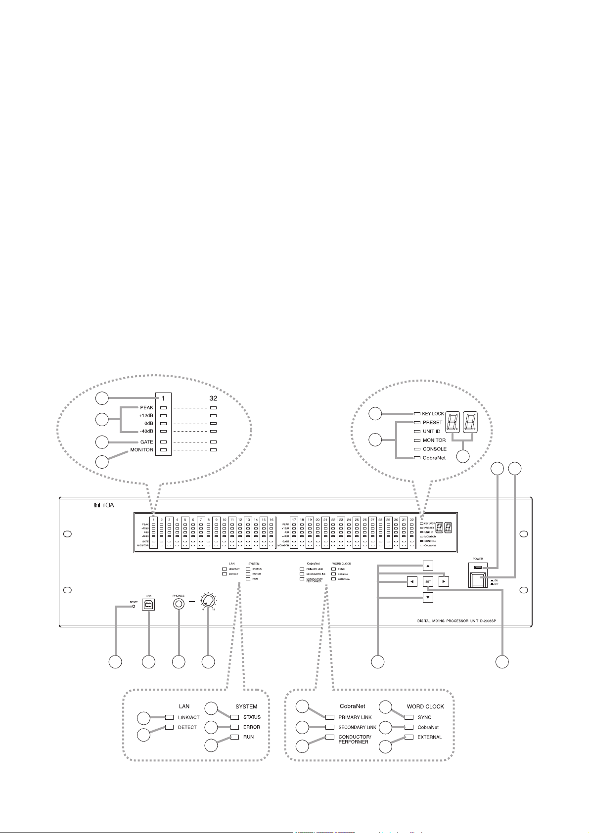
2.1. D-2008SP Digital Mixing Processor Unit
The D-2008SP Digital Mixing Processor Unit is designed to have up to 32 audio inputs and outputs in total.
A built-in multiple signal processing functions permit the unit to be used as both a mixer and a signal
processor.
Its audio input/output and control ports can accept plug-in modules, making the unit have a maximum of 32
inputs or 32 outputs and up to 2 control modules.
Using the following optional modules enables the unit to perform their functions: Two D-983s Remote Control
Module for providing a maximum of 48 contact inputs and 32 contact outputs, D-984VC VCA Control Module
for VCA control, and D-2000CB CobraNet Interface Module for audio data transfer between CobraNet
devices.
Each function can be set using the D-2000 Setting Software.
Operation can be performed through the front key operation and from a PC with the D-2000 Setting Software
installed.
The D-2012C Remote Console Unit, when connected, remotely controls the D-2008SP's basic operations
such as volume control.
It can be mounted in an EIA component rack (3U size*).
* 1U size = 44.5 mm or 1.75" (standard size)
Note
CobraNet is a trademark of Cirrus Logic, Inc.
[Front]
3
4
5
6
7
8
9
2
1
10 11 12 13
18
16
17
19
20
21
22
23
14 15
24
25
26
Page 7

7
1. Power switch [POWER ON/OFF]
Power is switched on and off with each
depression of this switch.
2. Power lamp
Lights when the power switch is set to ON.
3. Monitor number
Number of channel to be monitored using
headphones.
4. Level indicators [PEAK, +12 dB, 0 dB, –40 dB]
Indicate the signal level of each individual
channel.
Indicate the PFL (pre-fader level) value for the
input channel, and the AFL (after-fader level)
value for the output channel.
When an output channel is muted, only the
PEAK indicator lights. When all output channels
are muted by the "All Mute" function, all the
PEAK indicators flash.
5. Gate indicator (Orange)
Lights when the gate* is activated.
* This function passes, attenuates, or cuts the
input signal depending on its signal level.
6. Monitor selection indicator (Orange)
Lights to indicate the corresponding channel is
selected for monitoring using headphones.
7. Key lock indicator (Red)
Lights when key lock function is enabled.
8. Item selection indicators [PRESET, UNIT ID,
MONITOR, CONSOLE, CobraNet] (Green)
The indicator of the item selected with the
Selection keys (14) lights.
9. Number display
Displays the number of the preset memory
recalled.
10. Reset switch
Restarts the D-2008SP when pressed.
Press the switch (recessed) with a pen tip.
Note
Reactivating the unit stops audio signals
currently being output.
11. USB terminal
Not used.
12. Headphone jack
Audio outputs for the channel of which Monitor
selection indicator (6) is lighting can be
monitored. Connect stereo headphones of 16 Ω
or more. Adjust the monitor volume with the
headphone volume control knob (13).
13. Headphone volume control knob
Adjusts the headphone volume.
14. Selection keys
Use the Up and Down keys to select the Item
selection indicator.
Use the Left and Right keys to select the preset
memory number when recalling the preset
memory or the desired monitor number when
MONITOR is selected.
15. Set key
Used for preset memory recall or key lock
setting.
16. LAN LINK/ACT indicator (Green)
Lights when the LAN connector on the rear panel
is connected, and flashes during LAN
communications.
17. LAN DETECT indicator (Orange)
Lights when this unit is selected on the D-2000
Setting Software.
18. SYSTEM STATUS indicator (Green)
Lights when the unit is in communication with a
PC.
19. SYSTEM ERROR indicator (Red)
Lights while the unit is being activated, and goes
out after the activation has been completed.
If this indicator remains lit even after activation
completion, this indicates an internal fan failure.
(For the relationship between the indicator and
D-2008SP status, refer to the table on p. 8.)
20. SYSTEM RUN indicator (Green)
Lights when the unit is in normal operation, and
goes out when a failure occurs.
(For the relationship between the indicator and
D-2008SP status, refer to the table on p. 8.)
21. CobraNet PRIMARY LINK indicator (Green)
Flashes during CobraNet communications via
the primary port.
22. CobraNet SECONDARY LINK indicator
(Green)
Flashes during CobraNet communications via
the secondary port.
23. CobraNet CONDUCTOR/PERFORMER
indicator (Green)
Flashes when the primary port is in operation as
the conductor, and lights when it is in operation
as the performer.
24. WORD CLOCK SYNC indicator (Green)
Lights when internal word clock synchronization
is stable. Goes out if the clock gets out of
synchronization, then the internal mute functions,
causing the audio outputs to be interrupted. Even
if once the clock had got out of synchronization,
when the internal clock has stabilized, such
operation state automatically returns to normal.
Page 8
8
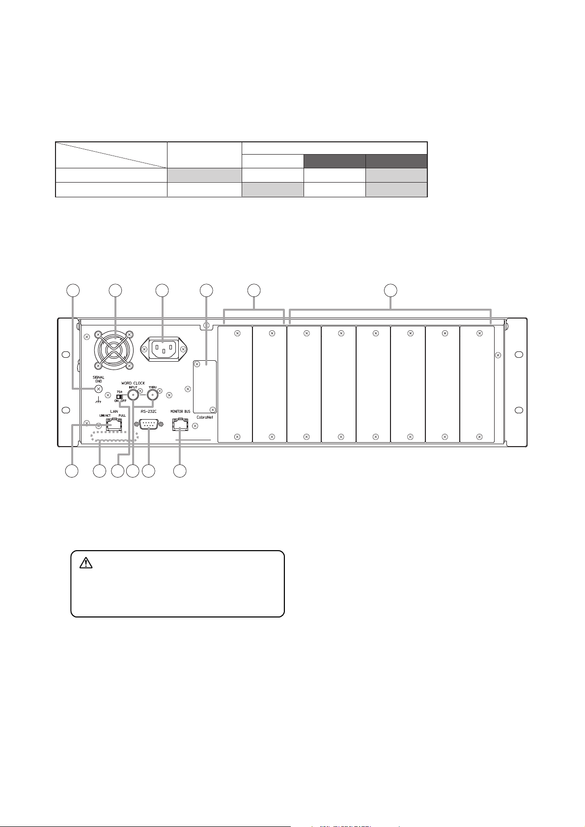
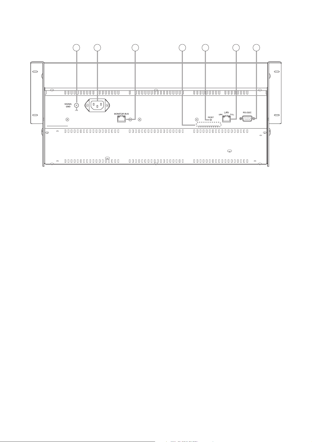
[Rear]
27. Functional earth terminal [SIGNAL GND]
Note: This terminal is not for protective earth.
28. Cooling fan
29. AC Inlet
Connect this inlet to the wall AC outlet using the
supplied power cord.
The socket-outlet shall be installed near the
equipment and the plug (disconnecting device)
shall be easily accessible.
30. CobraNet interface module slot
Accepts the D-2000CB CobraNet Interface
Module, allowing audio transmission with other
CobraNet equipment.
31. Input/output and remote control modules
slots (7 – 8)
Accept the input, output or remote control
modules.
Insert the input module to use as input, output
module to use as output, and remote control
module to use as control input.
32. Input/output module slots (1 – 6)
Accept the input or output modules.
Insert the input module to use as input, and
output module to use as output.
33. LAN connection terminal
Connect this terminal to a 10BASE-T- or
100BASE-TX-compatible network.
This terminal can also be connected to a PC and
D-2012C via a switching hub.
(For the IP address setting, refer to "Network
Settings" of the separate software setting
manual.)
CAUTION
Do not block the fan exhaust vent. Doing so
may cause heat to build up inside the unit and
result in fire.
25. WORD CLOCK CobraNet indicator (Green)
Lights when the master of the internal word clock
gets synchronization from CobraNet.
26. WORD CLOCK EXTERNAL indicator (Green)
Lights when the master of the internal word clock
gets synchronization from the external word
clock generator connected to the rear panel's
word clock input.
• SYSTEM ERROR and SYSTEM RUN indicators vs. D-2008SP status
D-2008SP status
Indicator
SYSTEM ERROR
SYSTEM RUN
Note
If both indicators light or remain unlit after the unit activation is complete, cycle the power. If the situation does not change
after the unit power-up, the unit may break down. Contact your TOA dealer.
During activation
Lit
Unlit Unlit
Normal state System error
Lit
After activation completion
Fan error
UnlitUnlit
Lit
Lit
27 28 29 30 31 32
33 34 35 36 37 38
Page 9

9
34. MAC address
This is the address* used by the unit. Since the
relationship of the unit's location to its MAC
address is established when setting the network
attributes, keep track of this relationship for later
use.
* The inherent address assigned to each network
component, expressed in 12-digit hexadecimal
notation.
35. Word clock termination switch
Terminates the word clock connection at 75 Ω.
To terminate the word clock connection at this
unit, shift the switch to the "ON" position. In other
cases, shift it to the "OFF" position. (Factory
preset: OFF)
36. Word clock terminals
Used to input and output the word clock which
synchronizes the audio signal processing with
that of external equipment. Connect a
commercially available word clock generator.*
Helps to stabilize the system that uses two or
more CobraNet devices.
As “Through output” (THRU) is not electrically
buffered, it can be used for input.
* Two or more CobraNet devices can be
connected in series using the Through output.
However, it is recommended to connect the
CobraNet device with the word clock generator
on a one-on-one basis.
37. RS-232C terminal
A communications connector for other control
equipment.
38. Monitor bus terminal
An audio transmission connector for the D2012C
Connects to the D-2012C's Monitor bus terminal.
Audio signals are output to the D-2012C's
headphone jack through the monitor bus or audio
signals from the D-2012C's Line input terminal
are input to the monitor bus.
Page 10
10
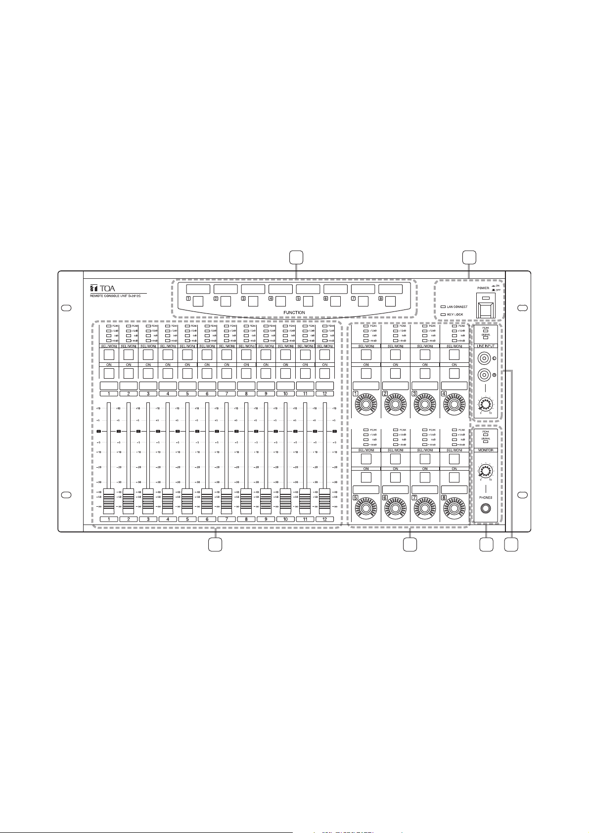
2.2. D-2012C Remote Console Unit
The D-2012C is designed to be used with the D-2008SP Digital Mixing Processor. The D-2012C can be LANconnected to the D-2008SP Processor to allow remote operation of input and output channel volume
adjustment, signal level monitoring, contact control and preset memory recall, etc. The D-2012C is equipped
with line inputs and audio monitor bus terminal. A PC can be connected to perform such settings as selection
of channels for operation and assigning functions to the function keys, using the D-2000 setting software
supplied with the D-2008SP Processor. Up to 4 different fader layers can be set when assigning channels to
each motorized fader and rotary encoder, allowing an individual D-2012C unit to operate up to 80 channels in
monaural. More channels can be operated by performing settings for stereo link and grouping (refer to p. 60
for details about the fader layer). It can be mounted in an EIA Standard component rack (6U* size). It can also
be used as a desktop unit in combination with the optional D-2012AS Console Case.
* 1U size = 44.5 mm or 1.75" (reference size)
[Operation panel]
AB
C D EF
Page 11
11
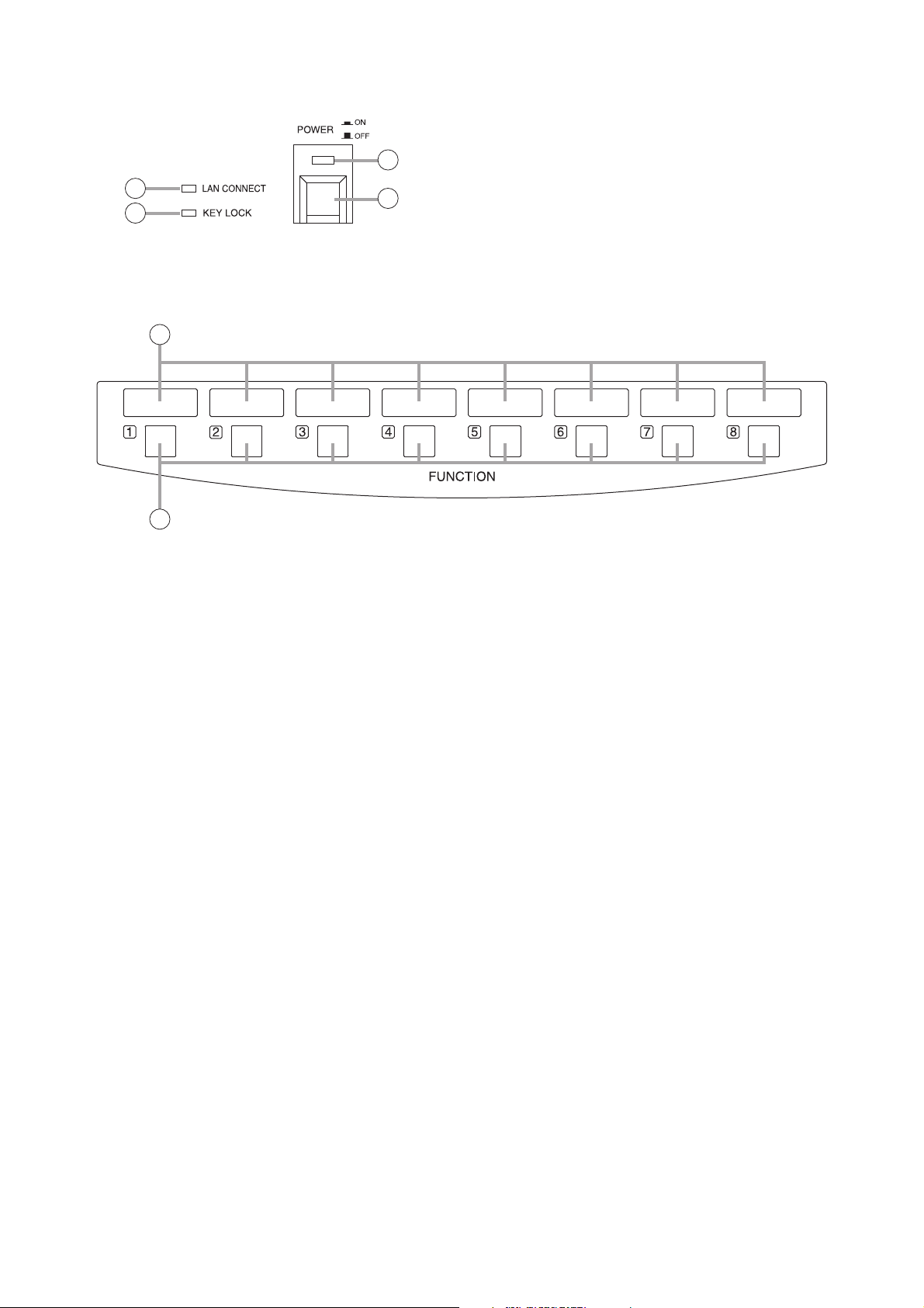
• A-Section
• B-Section
1. Power switch
Power is switched on and off with each
depression of this switch.
2. Power indicator
Lights when the power is switched on.
3. LAN connection indicator
Displays the connection status of the D-2008SP
to be controlled.
Lit: When all the D-2008SP units to be
controlled are in controllable state.
Flashing: When both controllable and
uncontrollable D-2000SP units exist in
a system where multiple D-2008SP
units to be controlled are used.
Unlit: When all the D-2008SP units to be
controlled are in uncontrollable state.
If there exists any uncontrollable D-2008SP,
check the D-2008SP's power supply and
connections.
4. Key lock indicator
Lights red when the operation keys or knobs are
locked.
5. Write-in space
Write the name of the function assigned to the
key, etc. in these spaces.
6. Function keys (1 – 8)
Execute contact control, preset memory recall or
other functions assigned to the keys.
Use the D-2000 Setting Software to set functions
and assign them to the keys.
2
3
1
4
5
6
Page 12
12
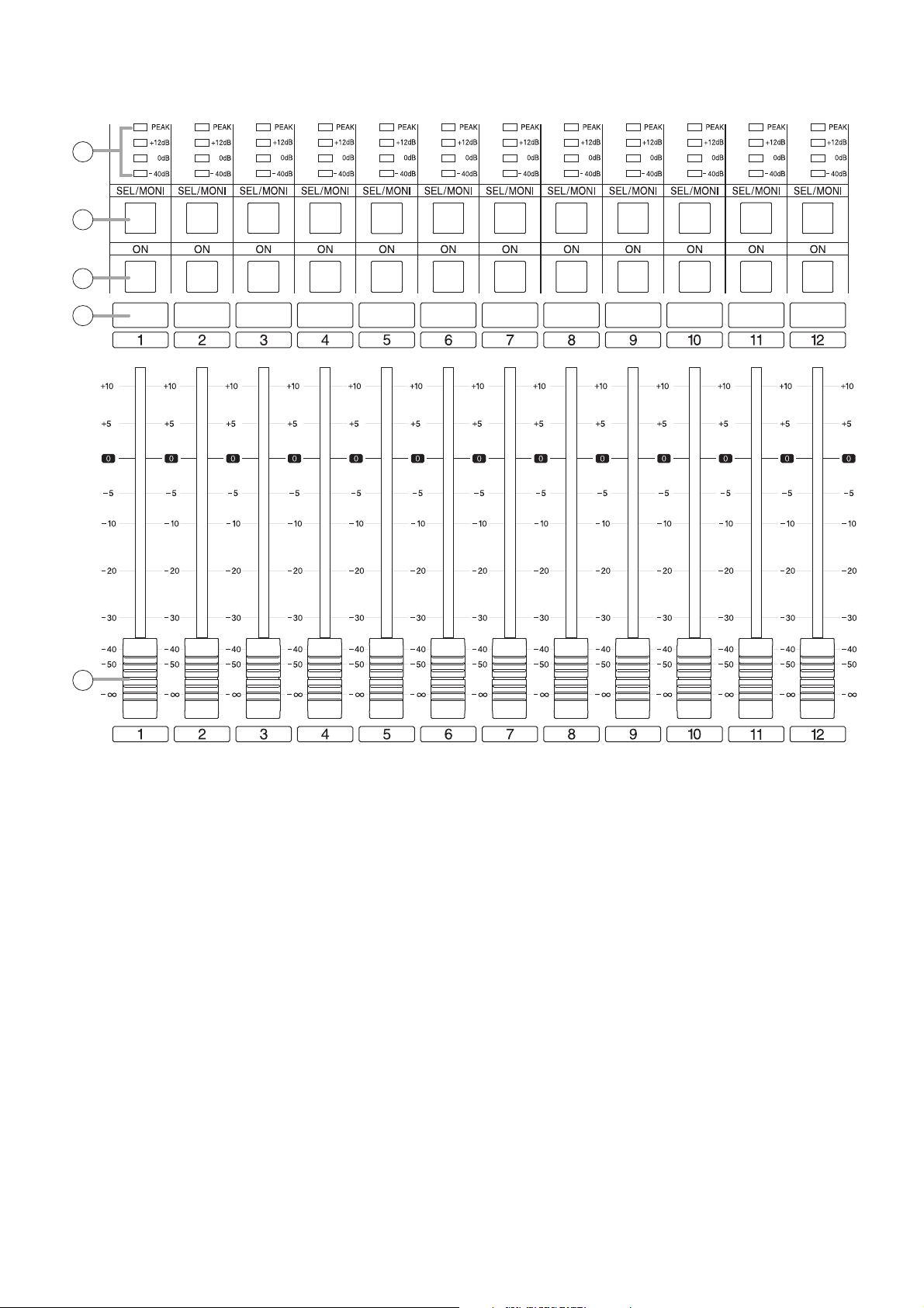
• C-Section
7. Level indicators [PEAK, +12 dB, 0 dB, –40 dB]
Indicate signal levels for each channel. Pre-fader
value is indicated for input channels and postfader value for output channels. Adjust the sound
volume so that the Peak indicator does not
continuously remain lit.
8. Monitor channel selector keys
Select the channel to be monitored. Pressing a
key causes it to light and allows its
corresponding channel to be monitored. Pressing
the key again causes the light to go out,
disabling monitoring.
It can be enabled to switch the D-2008SP's
selection channel on the D-2000 Setting
Software in synchronization with this key
operation. (For details, read the separate Setting
Software Instructions, "Console SEL/MONI key
interlock setting.")
9. Channel ON/OFF keys
Turn on or off the output for each channel.
Pressing a key causes it to light and the signal of
its corresponding channel to be output. When
pressed again, the light goes out and the
channel's signal output is stopped.
10. Write-in space
Write the name of the input or output channel,
etc. in these spaces.
11. Motorized faders (1 – 12)
Adjust the volume of each input or output
channel. With reference to fader position "0," the
position "–∞" provides the minimum volume, and
position "+10" the maximum volume.
Use the D-2000 Setting Software to perform
settings for the input or output channels for which
the volume is adjusted.
7
8
9
10
11
Page 13
13
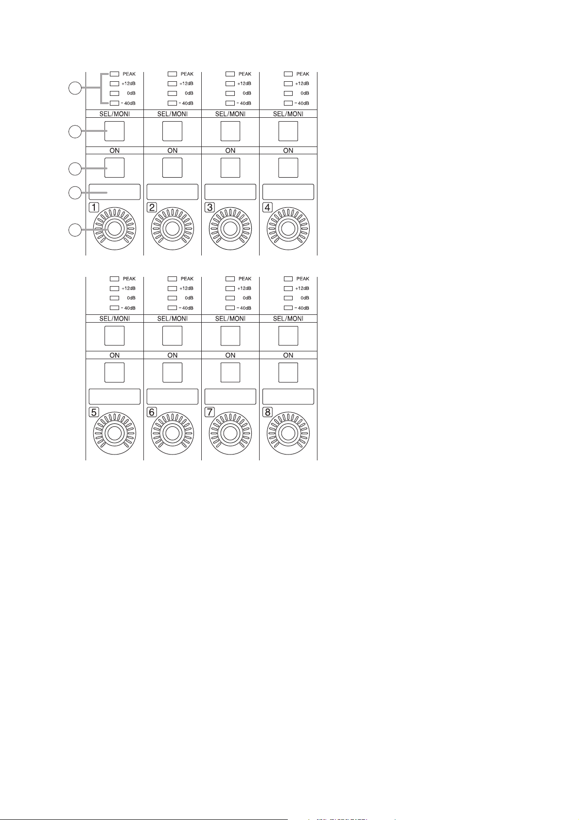
• D-Section
Note: Refer to p. 12 for names and functions of parts 7 – 10.
12. Rotary encoders (1 – 8)
Adjust the volume of each input or output
channel. The volume increases as the encoder is
rotated clockwise, and decreases as it is rotated
counterclockwise. (The knob rotates endlessly.)
The volume indicators around the knob light
depending on the rotation of the knob.
Use the D-2000 Setting Software to perform
settings for the input or output channels for which
the volume is adjusted.
7
8
9
10
12
Page 14
14
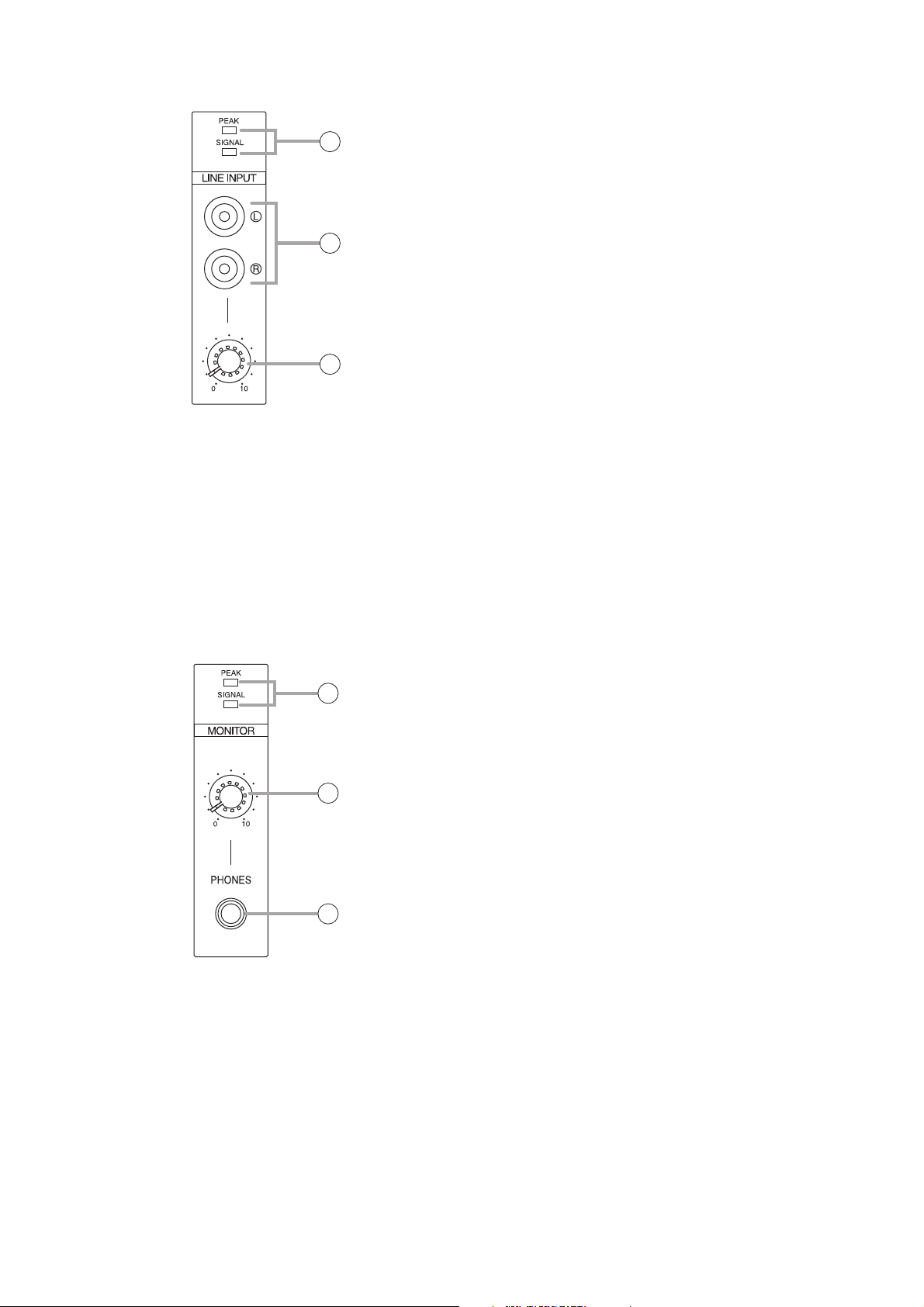
• E-Section
• F-Section
13. Line input signal level indicators
[SIGNAL, PEAK]
Display the signal level set with the Line input
volume control (15). The SIGNAL indicator lights
when a signal exceeding the reference level of
–20 dB is fed to the line input terminal. If a signal
at the line input terminals clips, the PEAK
indicator lights.
14. Line input terminals
Connect stereo equipment of stereo line level of
–10 dB* and 10 kΩ to these terminals. When
using these terminals, perform settings on the D2008SP side using the D-2000 Setting Software.
* 0 dB = 0.775 V
15. Line input volume control knob
Adjusts the signal input level from equipment
connected to the line input terminal. The volume
increases as the control knob is rotated
clockwise and decreases as it is rotated
counterclockwise. Adjust the level so that the
SIGNAL indicator lights without lighting the
PEAK indicator.
16. Monitor signal indicators [SIGNAL, PEAK]
Indicates the level of the signal being monitored.
The SIGNAL indicator lights when a signal being
monitored exceeding the reference level of –20
dB is fed to the line input terminal. If the signal
level approaches clipping volume, the PEAK
indicator lights. Select the channel to be
monitored using Monitor channel selector keys
(8).
17. Monitor volume control knob
Adjusts the volume of sound monitored by the
headphones connected to the Headphone jack.
The volume increases as the control knob is
rotated clockwise and decreases as it is rotated
counterclockwise.
18. Headphone jack
Applicable impedance is 16 Ω or greater. This
jack allows monitoring of the sound output from
the channel selected with the Monitor channel
selector keys (8). Plug in headphones of 16 Ω or
more to this jack. Adjust the monitor volume with
the Monitor volume control knob (17).
13
14
15
16
17
18
Page 15
15
[Connection panel]
19. Functional earth terminal
Note: This terminal is not for protective earth.
20. AC Inlet
Connect this inlet to the wall AC outlet using the
supplied power cord.
The socket-outlet shall be installed near the
equipment and the plug (disconnecting device)
shall be easily accessible.
21. Monitor bus terminal
An audio transmission connector for the D2008SP. Connects to the D-2008SP's Monitor
bus terminal. D-2008SP's audio signals are
output to the headphone jack through the
monitor bus or audio signals from the Line input
terminals (14) are input to the D-2008SP.
22. MAC address
This is the address* used by the unit. Since the
relationship of the unit's location to its MAC
address is established when setting the network
attributes, keep track of this relationship for later
use.
* The inherent address assigned to each network
component, expressed in 12-digit hexadecimal
notation.
23. Reset switch
Avoid touching this switch, as it is used only
during maintenance.
24. LAN connection terminal
Connect this terminal to a 10BASE-T- or
100BASE-TX-compatible network. This terminal
can also be connected to a PC and D-2008SP
via a switching hub.
(For the IP address setting, refer to "Network
Settings" of the separate software setting
manual.)
25. RS-232C terminal
This RS-232C connector is provided for
maintenance purposes.
19 20 21 22 23 24 25
Page 16
16
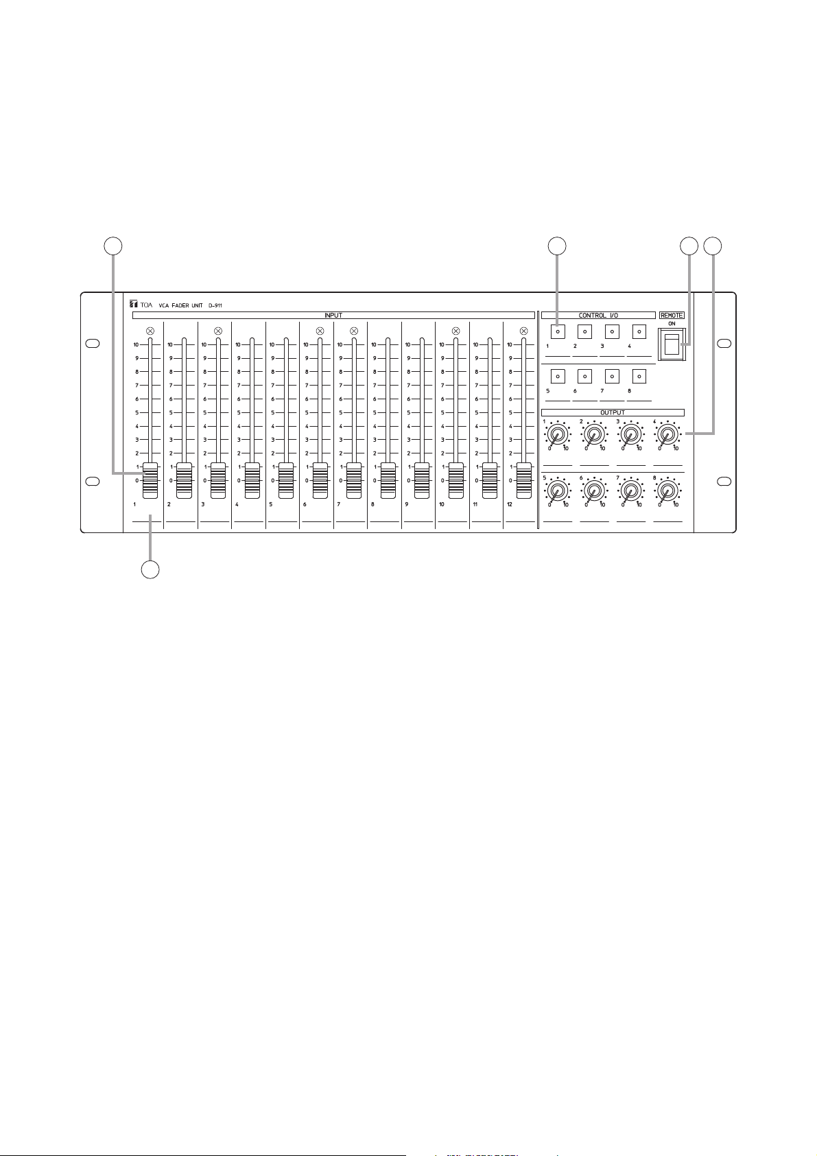
2.3. D-911 VCA Fader Unit
The D-911 VCA Fader Unit is designed for use with the D-2008SP.
Connecting to the D-984VC VCA Control Module installed in the D-2008SP permits volume adjustment of
input and output channels and contact controls of the D-2008SP. For details, refer to the instruction manual
enclosed with the D-911.
[Front]
1. Input fader
Adjusts the volume of each input equipment (i.e.
microphones and CD players). Fader position "0"
provides the minimum volume, and position "10"
the maximum volume.
Assign the channel to be operated using the D2000 Setting Software. It is also possible to
assign the channel as output fader.
2. Control key
Recalls preset memories or controls the contact.
Lights when the preset memory is recalled or the
contact is turned on.
Assign the contact functions using the D-2000
Setting Software.
3. Remote (Activation) switch
Setting this switch to the ON position closes the
remote (activation) output terminals (6) on the
rear panel, and setting this switch to the opposite
side opens the output terminals.
4. Output volume control knob
Adjusts the output volume. Position "0" provides
the minimum volume, and position "10" the
maximum volume.
Assign the channel to be operated using the D2000 Setting Software.
It is also possible to assign the knob as input
volume control knob.
5. Write-in space
Used to fill in input/output name, preset memory
contents, or other notes for convenience of
operation.
1
5
2 3 4
Page 17
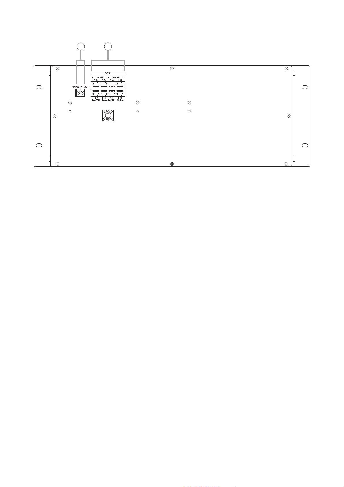
17
6. Remote (activation) output terminals
Setting the Remote (activation) switch (3) to the
ON position closes the output.
7. VCA control module connection terminals
These terminals are used exclusively for the D984VC VCA Control module. Use an RJ45
connector for connection.
Note
Avoid connecting any other than the D-984VC to
these terminals.
[Rear]
6 7
Page 18
18
2.4. Optional Modules
Notes
• Make sure that the power is switched OFF before attaching or detaching modules.
• To avoid failures due to static electricity, do not touch the parts or terminals on the circuit board of both the
unit and module.
• Ensure that the module is installed and secured with screws in the correct position.
• Cover idle slots with the blank panels attached to the unit as shipped by the factory.
• Two silver slotted screws at the upper and lower portion of the module face are handles used for module
detachment. Never rotate them because they do not function as screws.
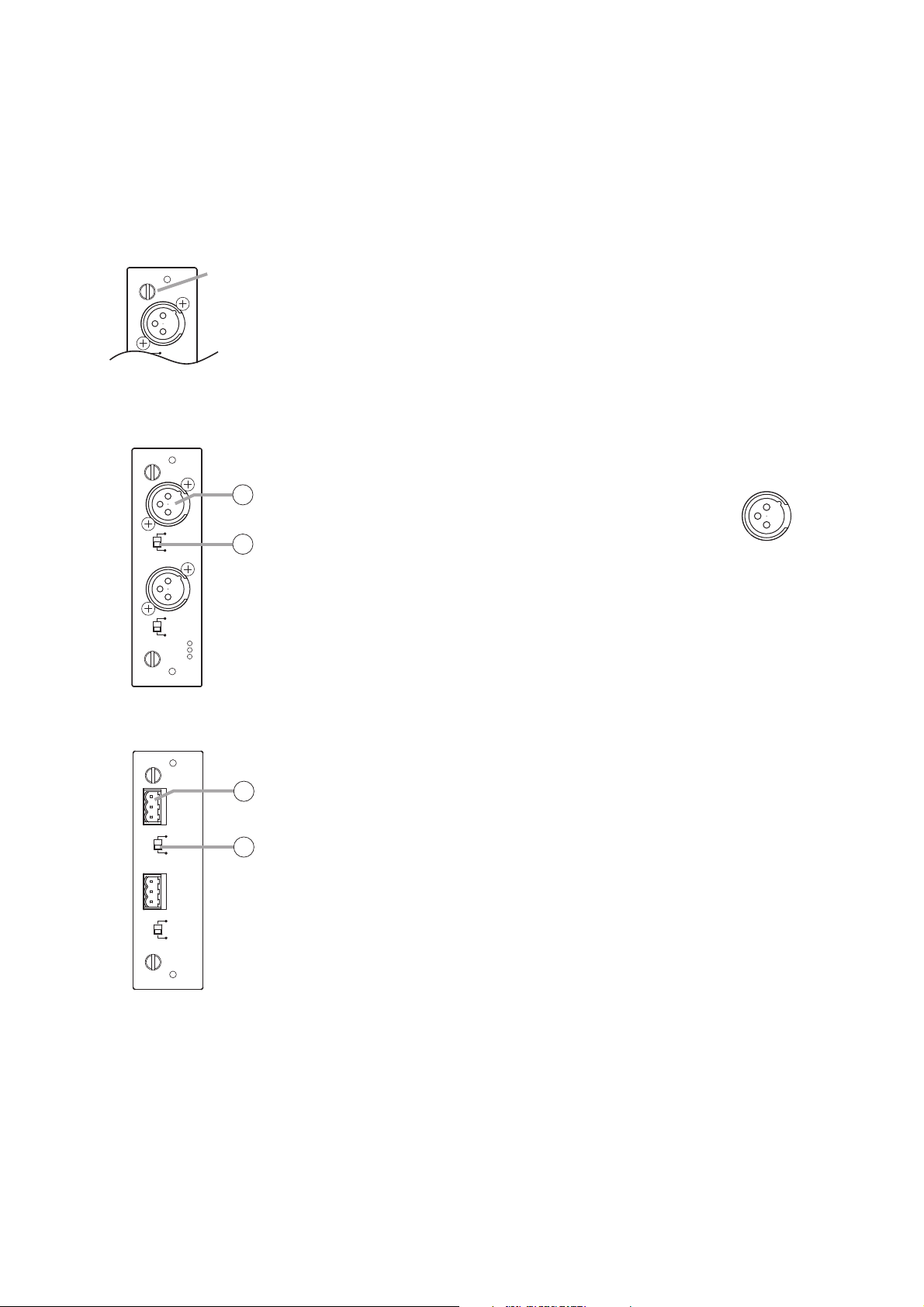
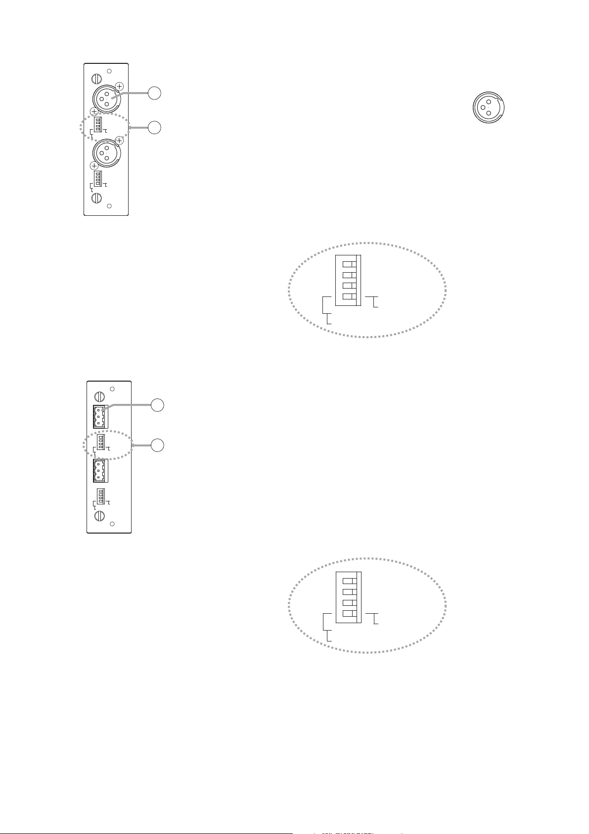
2.4.1. D-921F Microphone/Line Input Module
1. Monaural input terminal [1, 2] (XLR-3-31 equivalent)
Electronically-balanced input terminal.
(Pin 1: Ground, Pin 2: Hot, Pin 3: Cold)
Use XLR-3-12C or equivalent for connection.
Input sensitivity (–50/–36/–10/+4 dB) and
phantom power (+15 V) ON/OFF can be set by
a PC using the setting software supplied with
the D-2008SP.
2. Ground lift switch [GND LIFT/NORMAL]
Hum noise may be generated due to ground loops created when the unit
is connected to other equipment. Setting the switch to the GND LIFT
position cuts the ground loop.
2.4.2. D-921E Microphone/Line Input Module
3. Monaural input terminal [1, 2]
Electronically-balanced, removable terminal block.
(H: Hot, C: Cold, E: Ground)
Input sensitivity (–50/–36/–10/+4 dB) and phantom power (+15 V)
ON/OFF can be set by a PC using the setting software supplied with the
D-2008SP.
Note
Be sure to use the supplied removable terminal plugs (3P) for
connection.
4. Ground lift switch [GND LIFT/NORMAL]
Hum noise may be generated due to ground loops created when the unit
is connected to other equipment. Setting the switch to the GND LIFT
position cuts the ground loop.
MIC/LINE INPUT MODULE
GND LIFT
Handle
1
MIC/LINE INPUT MODULE [–50 / –36 / –10 / +4 dB] model D-921F
GND LIFT
NORMAL
1
1
2
GND LIFT
NORMAL
2
1
: E
: H
2
: C
3
2: Hot
3: Cold
1: Ground
MIC/LINE INPUT MODULE [–50 / –36 / –10 / +4 dB] model D-921E
E
C
H
GND LIFT
NORMAL
E
C
H
GND LIFT
NORMAL
3
1
4
2
Page 19
19
2.4.4. D-922E Microphone/Line Input Module
7. Monaural input terminal [1, 2]
Electronically-balanced, removable terminal block.
(H: Hot, C: Cold, E: Ground)
Note
Be sure to use the supplied removable terminal plugs (3P) for
connection.
8. Input sensitivity switch [PHANTOM, GND LIFT, MIC/LINE]
4-pole switch. Enables phantom power (+15V; ON/OFF, enabled only
when set to the MIC position), ground lift and input sensitivity.
Input sensitivity: –36 or –50 dB (MIC mode) / –10 or +4 dB (LINE mode)
Note
To use as monitor input, set the "PHANTOM" switch to OFF and "Input
sensitivity" switch to "+4 dB (LINE)."
2.4.3. D-922F Microphone/Line Input Module
5. Monaural input terminal [1, 2] (XLR-3-31 equivalent)
Electronically-balanced input terminal.
(Pin 1: Ground, Pin 2: Hot, Pin 3: Cold)
Use XLR-3-12C or equivalent for connection.
6. Input sensitivity switch [PHANTOM, GND LIFT, MIC/LINE]
4-pole switch. Enables phantom power (+15 V; ON/OFF, enabled only
when set to the MIC position), ground lift and input sensitivity.
Input sensitivity: –36 or –50 dB (MIC mode) / –10 or +4 dB (LINE mode)
Note
To use as monitor input, set the "PHANTOM" switch to OFF and "Input
sensitivity" switch to "+4 dB (LINE)."
MIC/LINE INPUT MODULE model D-922F
ON
NORMAL
MIC
-10dB(LINE)
-50dB(MIC)
ON
NORMAL
MIC
-10dB(LINE)
-50dB(MIC)
OFF : PHANTOM
LIFT : GND
LINE
+4dB(LINE)
-36dB(MIC)
OFF : PHANTOM
LIFT : GND
LINE
+4dB(LINE)
-36dB(MIC)
5
1
3: Cold
6
2
2: Hot
1: Ground
ON
NORMAL
MIC
OFF : PHANTOM
LIFT : GND
LINE
-10dB(LINE)
-50dB(MIC)
+4dB(LINE)
-36dB(MIC)
MIC/LINE INPUT MODULE model D-922E
7
8
2
NORMAL
NORMAL
ON
MIC
ON
MIC
-10dB(LINE)
-50dB(MIC)
-10dB(LINE)
-50dB(MIC)
E
CH1
OFF : PHANTOM
LIFT : GND
LINE
+4dB(LINE)
-36dB(MIC)
E
C
H
OFF : PHANTOM
LIFT : GND
LINE
+4dB(LINE)
-36dB(MIC)
ON
NORMAL
MIC
OFF : PHANTOM
LIFT : GND
LINE
-10dB(LINE)
-50dB(MIC)
+4dB(LINE)
-36dB(MIC)
Page 20
20
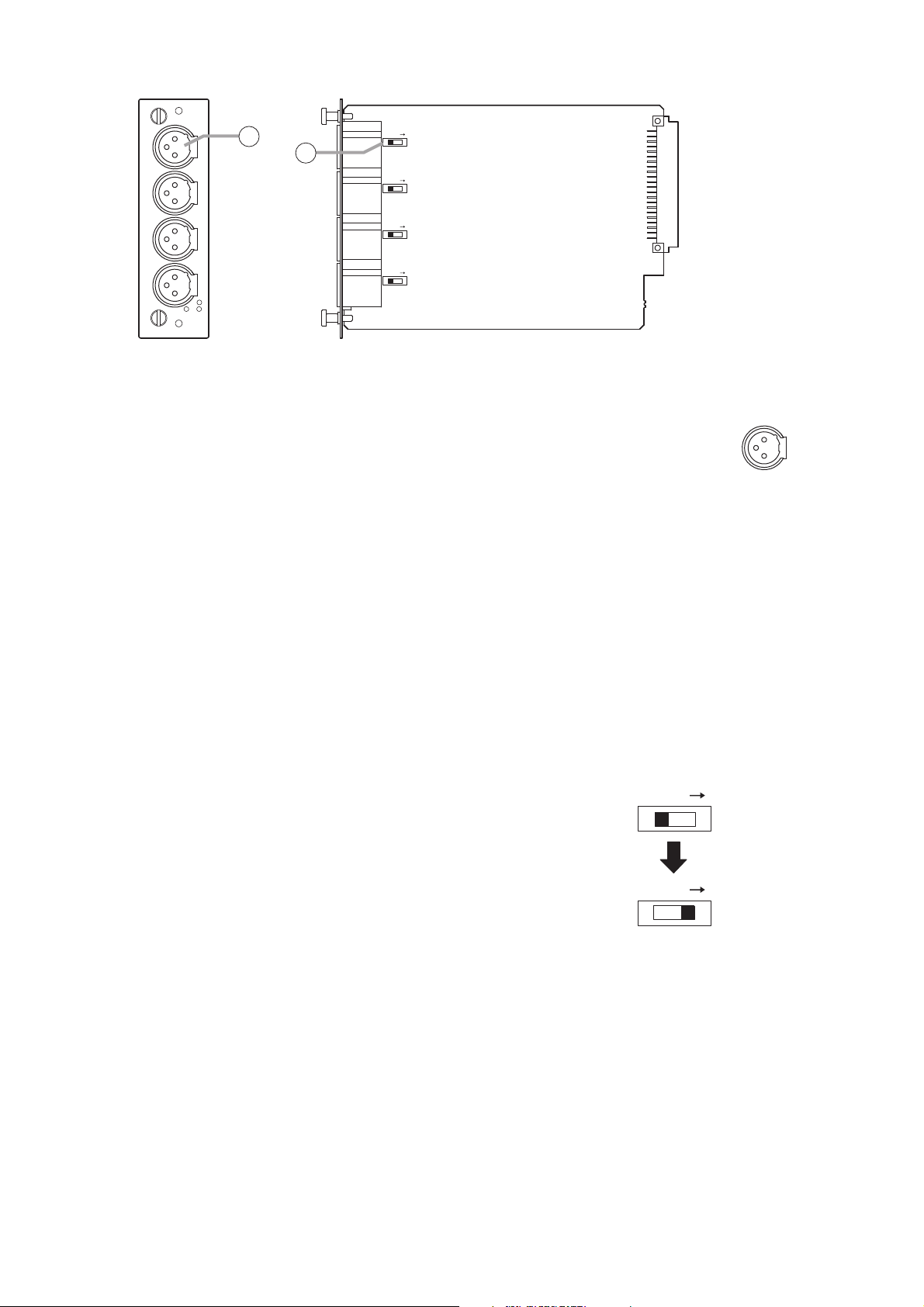
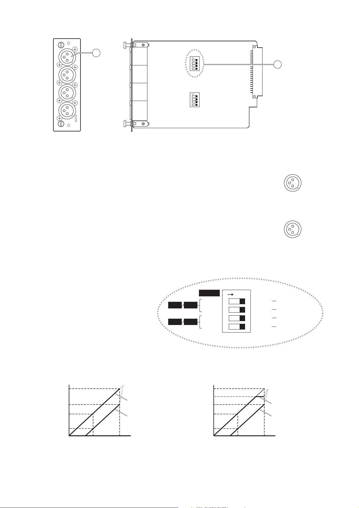
2.4.5. D-2000AD1 Microphone/Line Input Module
9. Monaural input terminal [1, 2, 3, 4] (XLR-3-31 or equivalent)
Electronically balanced input terminal.
(Pin 1: Ground, Pin 2: Hot, Pin 3: Cold)
Use XLR-3-12C or equivalent for connection.
Input sensitivity (–50/–36/–10/+4 dB) and phantom power (+48 V) ON/OFF
settings can be performed by a PC using the D-2000 Setting software
supplied with the D-2008SP.
Notes
• Be sure to turn off the phantom power (+48 V) when using an unbalanced microphone or equipment
such as a CD player or effecter other than a microphone. As doing otherwise may cause damage to the
unit.
• To insert or remove a condenser microphone that requires external power source, turn down the fader of
the corresponding channel, turn off its channel and the phantom power (+48 V), then wait at least 1
minute before inserting or removing. As doing otherwise may cause damage or failure to this module
and microphone.
• Noise may be produced when or after the phantom power (+48 V) is turned on or off. Be sure to turn on
or off the phantom power (+48 V) after turning down the fader of the corresponding channel and turning
off the channel.
Also, never operate the fader nor turn on and off the channel for 1 minute after turning on or off the
phantom power (+48 V).
• Current consumption of the phantom power supply must be 5 mA or less per channel.
10. Ground lift switch
When the D-2008SP is connected to other equipment, a ground may
create a loop, potentially generating hum noise. In such cases, the ground
loop can be cut off by setting the DIP switch on the circuit board to the
LIFT position.
Note
When shifting the DIP switch, never touch other parts on the circuit board.
MIC/LINE INPUT MODULE [–50
LIFT
LIFT
LIFT
LIFT
/
–36
/
–10
/
+4 dB]
model D-2000AD1
9
1
2
3
4
2
: H
1
3
: E
: C
10
3: Cold
2: Hot
1: Ground
LIFT
(Factory preset)
LIFT
(To the LIFT side)
Page 21
21
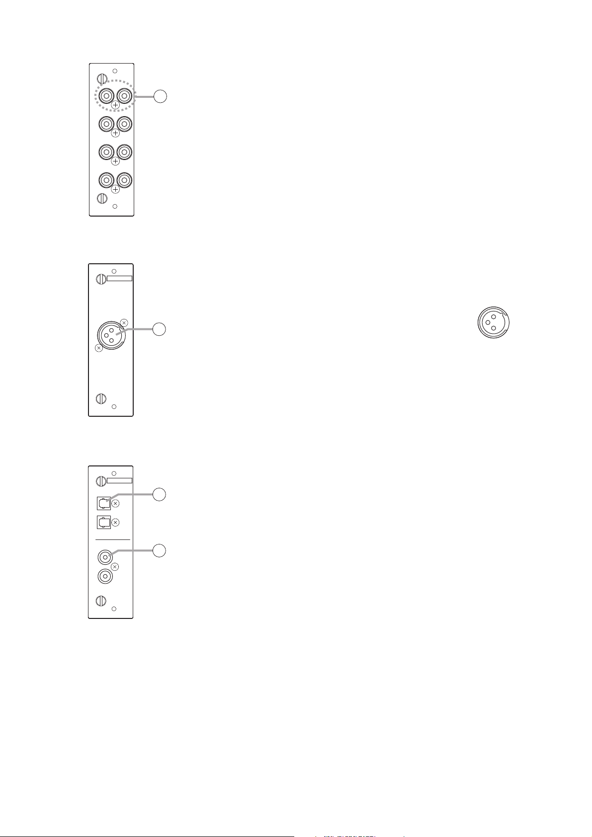
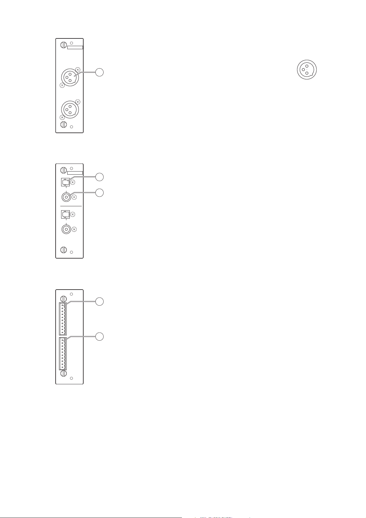
2.4.8. D-937SP Digital Input Module
Note
This module cannot be used as a monitor input.
13. Optical input terminal [OPTICAL, 1, 2]
Optical input terminal of S/PDIF format.
14. Coaxial input terminal [COAXIAL 3, 4]
Coaxial input terminal of S/PDIF format.
Notes
• Use a coaxial cable with characteristic impedance of 75 Ω for
connection.
• One of four line inputs (stereo) is selected. Input selection is performed
by a PC using the setting software supplied with the D-2008SP.
2.4.7. D-923AE Digital Input Module
12. AES/EBU digital input terminal [AES/EBU, 1/2]
(XLR-3-31 equivalent)
Digital input terminal of AES/EBU format.
(Pin 1: Ground, Pin 2: Signal, Pin 3: Signal)
Use the XLR-3-12C or equivalent for
connection.
Note
Use a digital audio cable with characteristic
impedance of 110 Ω for connection.
2.4.6. D-936R Stereo Input Module
Note
This module cannot be used as a monitor input.
11. Stereo input terminal [1L/1R, 2L/2R, 3L/3R, 4L/4R]
Unbalanced, RCA jack stereo input terminals. Either a single stereo input
can be selected from the 4 available stereo inputs or all 4 stereo
channels can be mixed.
Mode setting and stereo selection are performed by a PC using the
setting software supplied with the D-2008SP. They can also be remotely
selected by way of connected external equipment through the use of the
control module.
Input signal level: –10 dB
1R2R1L
11
2L
3L3R
4L4R
model D-936RSTEREO SELECT INPUT MODULE [ –10 dB]
DIGITAL IN
12
1/2
AES/EBU
model D-923AEDIGITAL INPUT MODULE
OPTICAL
DIGITAL IN
13
1
2
14
3
model D-937SPDIGITAL INPUT MODULE
COAXIAL
4
3: Signal
2: Signal
1: Ground
Page 22
22
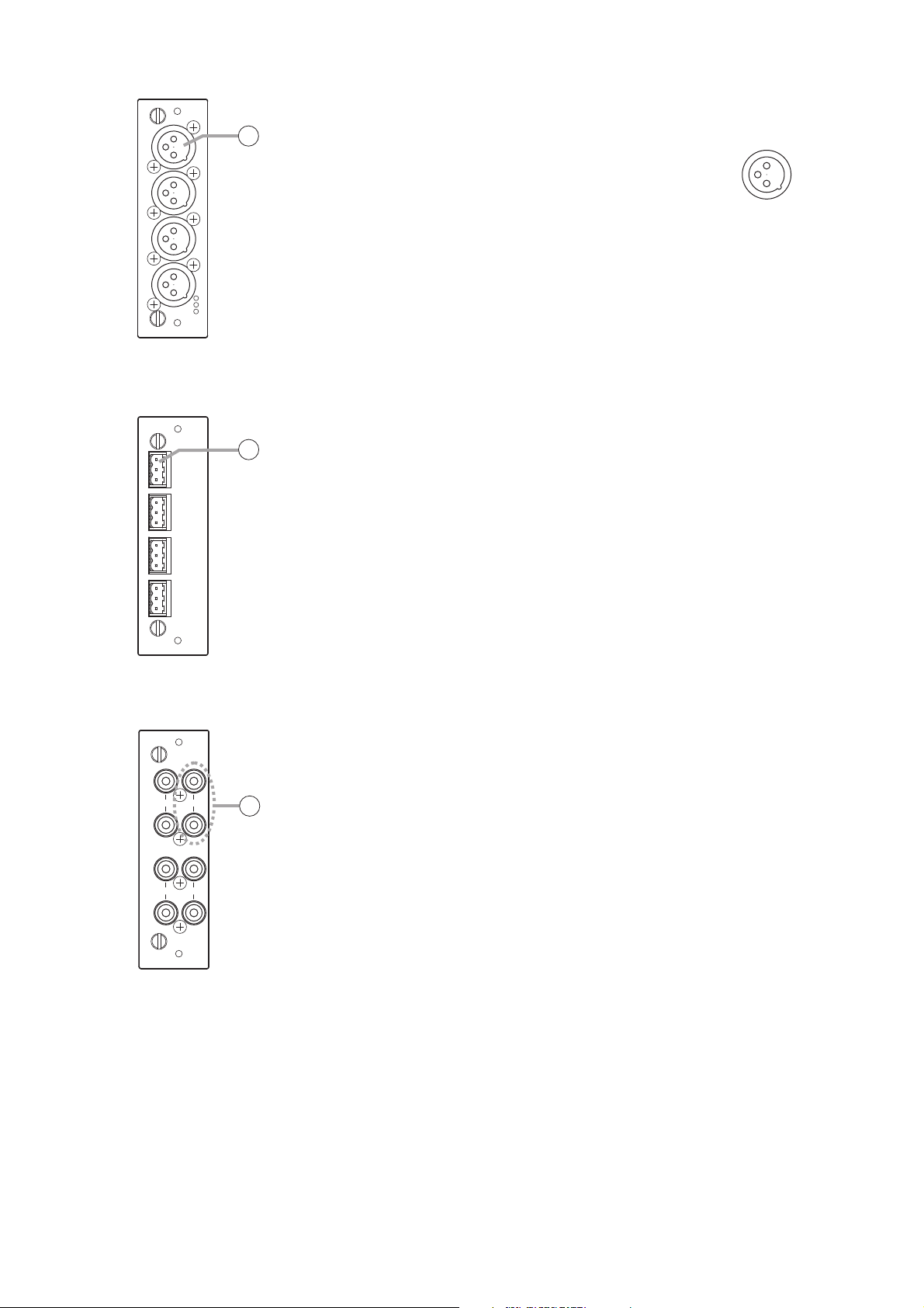
2.4.9. D-971M Line Output Module
15. Monaural output terminal [1, 2, 3, 4] (XLR-3-32 equivalent)
Electronically-balanced output terminal.
(Pin 1: Ground, Pin 2: Hot, Pin 3: Cold)
Output signal level: +4 dB
Use XLR-3-11C or equivalent for connection.
2.4.10. D-971E Line Output Module
16. Monaural output terminal [1, 2, 3, 4]
Electronically-balanced, removable terminal block.
(H: Hot, C: Cold, E: Ground.)
Output signal level: +4 dB
Note
Be sure to use the supplied removable terminal plugs (3P) for
connection.
2.4.11. D-971R Line Output Module
17. Monaural output terminal [1(L), 2(R), 3(L), 4(R)]
Unbalanced, RCA jack output terminals. Each output is equipped with a
2-channel splitter.
Output signal level: –10 dB
LINE OUTPUT MODULE
[+4 dB]
model D-971M
15
1
2
3
4
1
: E
: H
2
: C
3
LINE OUTPUT MODULE [+4 dB]
E
C
1
H
E
C
2
H
E
C
3
H
E
4
C
model D-971E
H
16
3: Cold
1: Ground
2: Hot
2(R) 1(L)
4(R) 3(L)
model D-971RLINE OUTPUT MODULE [–10 dB]
17
Page 23
23
Notes
• Do not touch any other parts on the pc board when operating the switch.
• The maximum output level is +18 when set to +4 dB/unbalanced output.
2.4.12. D-2000DA1 Line Output Module
18. Monaural output terminal [1, 2, 3, 4] (XLR-3-32 equivalent)
Balanced (electronically-balanced) or unbalanced output, switchable.
• Balanced output mode (factory preset)
(Pin 1: Ground, Pin 2: Hot, Pin 3: Cold)
• Unbalanced output mode
(Pin 1: Ground, Pin 2: Hot, Pin 3: No connection but may be
connected to Pin 1 Ground)
The output level can be set to either +4 dB or –10 dB.
Use XLR-3-11C or equivalent for connection.
Notes
• Be sure to place this terminal in Unbalanced output mode for
accepting an Unbalanced input device. Balanced output mode can
also be used in this case, but the output level decreases by 6 dB.
• Be sure to place this terminal in Balanced output mode for accepting
a Balanced input device. Unbalanced output mode can also be used
in this case, but the maximum output level decreases by 6 dB.
19. Output level/output mode setting switch
4-position DIP switch for setting the
output level and output mode.
The output level can be set to either
+4 dB or –10 dB.
The output mode can be set to either
balanced output (electronicallybalanced, BAL) or unbalanced output
(UNBAL).
The output is factory-preset to
+4 dB/balanced output (BAL). (All
switches are set to ON.)
The output level in each output mode is shown below.
LINE OUTPUT MODULE
18
1
[–10/+4 dB]
2
ON
19
model D-2000DA1
3
4
1
: E
: H
2
: C
3
ON
[Balanced output mode]
3. Cold
[Unbalanced output mode]
3. No connection
(may be connected
to Pin 1 Ground)
1. Ground
2. Hot
1. Ground
2. Hot
[Balanced output mode] [Unbalanced output mode]
+24 dB
+10 dB
+4 dB
Output level
–10 dB
Input level
Max. output level
Output level: +4 dB
Output level: –10 dB
0 dBFS–20 dBFS
DIP SW
–10 dBu
CH 3CH 1
UNBAL
–10 dBu
CH 4CH 2
UNBAL MODE
+24 dB
+18 dB
+10 dB
+4 dB
Output level
–10 dB
ON
Input level
(DEFAULT)
+4 dBu SIGNAL LEVEL
BAL MODE
+4 dBu SIGNAL LEVEL
BAL
Max. output level
Output level: +4 dB
Output level: –10 dB
0 dBFS–20 dBFS
Page 24
24
2.4.13. D-972AE Digital Output Module
18. AES/EBU digital output terminal [AES/EBU, 1/2, 3/4]
(XLR-3-32 or its equivalent)
Digital output terminal of AES/EBU format.
(Pin 1: Ground, Pin 2: Signal, Pin 3: Signal)
Use the XLR-3-11C or equivalent for
connection.
Note
Use the digital audio cable with characteristic
impedance of 110 Ω for connection.
2.4.14. D-961SP Digital Output Module
19. Optical output terminal [OPTICAL 1, 2]
Optical output terminal of S/PDIF format.
20. Coaxial output terminal [COAXIAL 1, 2]
Coaxial output terminal of S/PDIF format.
Note
Use a coaxial cable with characteristic impedance of 75 Ω for
connection.
Each pair of the S/PDIF optical output and the coaxial RCA jack output
delivers output in parallel.
2.4.15. D-981 Remote Control Module
21. Contact input terminal [INPUT, C, 1, 2, 3, 4, 5, 6, 7, 8, C]
Removable terminal block, 8-circuit contact input terminal.
Individual contact functions are assigned by a PC using the D-2000
Setting Software supplied with the D-2008SP.
Note
Be sure to use the supplied removable terminal plugs (10P) for
connection.
22. Contact output terminal [OUTPUT, C, 1, 2, 3, 4, 5, 6, 7, 8, C]
Removable terminal block, 8-circuit contact output terminal.
Individual contact functions are assigned by a PC using the D-2000
Setting Software supplied with the D-2008SP.
DIGITAL OUT
AES/EBU
20
1/2
model D-972AEDIGITAL OUTPUT MODULE
3/4
AES/EBU
OPTICAL
1
COAXIAL
OPTICAL
2
DIGITAL OUT
21
22
COAXIAL
model D-961SPDIGITAL OUTPUT MODULE
1: Ground
3: Signal
2: Signal
REMOTE CONTROL MODULE model D-981
C
1
2
3
4
INPUT
5
6
7
8
C
C
1
2
3
4
OUTPUT
5
6
7
8
C
23
24
Page 25
25
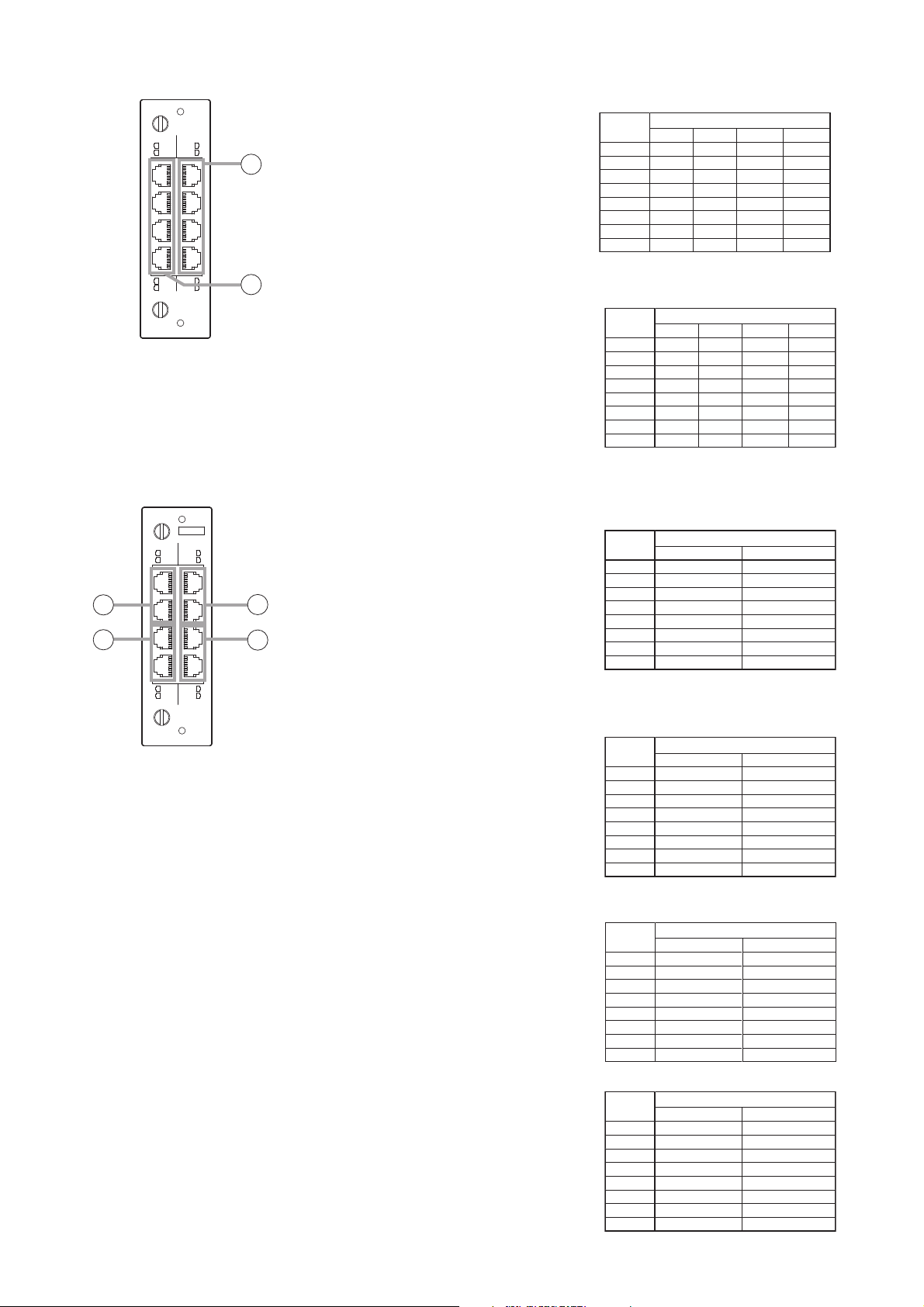
2.4.16. D-983 Remote Control Module
23. Contact input terminal [CTRL IN, 1-6, 7-12, 13-18, 19-24]
Six-circuit RJ45 contact input terminals.
Individual contact functions are assigned
by a PC using the D-2000 Setting
Software supplied with the D-2008SP.
24. Contact output terminal [CTRL OUT,1-4, 5-8, 9-12, 13-16]
Four-circuit RJ45 contact output
terminals.
Individual contact functions are assigned
by a PC using the D-2000 Setting
Software supplied with the D-2008SP.
2.4.17. D-984VC VCA Control Module
25. Input channel VCA terminal [IN CH, 1 – 6, 7 – 12]
RJ45 VCA terminals.
Assign the VCA channels to this terminal.
Up to 12 channels can be controlled.
The channel assignment can be
performed by a PC using the D-2000
Setting Software supplied with the D2008SP.
26. Output channel VCA terminal [OUT CH, 1 – 4, 5 – 8]
RJ45 VCA terminals.
Assign the VCA channels to this terminal.
Up to 8 channels can be controlled.
The channel assignment can be
performed by a PC using the D-2000
Setting Software supplied with the D2008SP.
27. Control input terminal [CTRL IN, 1 – 4, 5 – 8]
RJ45 Control Input terminals.
These RJ45 Control Input terminals
correspond to 8 control inputs.
Individual contact functions are assigned
by a PC using the D-2000 Setting
Software supplied with the D-2008SP.
28. Control output terminal [CTRL OUT, 1 – 4, 5 – 8]
RJ45 Control output terminals.
These RJ45 Control output terminals
correspond to 8 control outputs.
Individual contact functions are assigned
by a PC using the D-2000 Setting
Software supplied with the D-2008SP.
CTRL OUT CTRL IN
1-4
1-6
5-8
7-12
CONTROL UNITS FOR D-901 ONLY
25
9-12
13-18
13-16
19-24
model D-983REMOTE CONTROL MODULE
26
VCA
CTRL IN IN CH
1-4
1-6
5-8
7-12
CONTROL UNITS FOR D-901 ONLY
29
27
30
1-4
model D-984VCVCA CONTROL MODULE
5-8
CTRL OUT OUT CH
1-4
5-8
28
Pin No.
1
2
3
4
5
6
7
8
Pin No.
1
2
3
4
5
6
7
8
Pin No.
1
2
3
4
5
6
7
8
Pin No.
1
2
3
4
5
6
7
8
1 – 6
IN 1
IN 2
IN 3
IN 6
IN 5
IN 4
C
C
1 – 4
OUT 1
C 1
OUT 2
C 3
OUT 3
C 2
OUT 4
C 4
IN CH 1
IN CH 2
IN CH 3
IN CH 6
IN CH 5
IN CH 4
OUT CH 1
OUT CH 2
OUT CH 3
OUT CH 4
1 – 6
V
C
1 – 4
C
V
V
C
CTRL IN
7 – 12
IN 7
IN 8
IN 9
IN 12
IN 11
IN 10
C
C
CTRL OUT
5 – 8
OUT 5
C 5
OUT 6
C 7
OUT 7
C 6
OUT 8
C 8
IN CH
OUT CH
13 – 18
IN 13
IN 14
IN 15
IN 18
IN 17
IN 16
C
C
9 – 12
OUT 9
C 9
OUT 10
C 11
OUT 11
C 10
OUT 12
C 12
OUT CH 5
OUT CH 6
OUT CH 7
OUT CH 8
19 – 24
IN 19
IN 20
IN 21
IN 24
IN 23
IN 22
C
C
13 – 16
OUT 13
C 13
OUT 14
C 15
OUT 15
C 14
OUT 16
C 16
7 – 12
IN CH 7
IN CH 8
IN CH 9
IN CH 12
IN CH 11
IN CH 10
V
C
5 – 8
C
V
V
C
Pin No.
1
2
3
4
5
6
7
8
Pin No.
1
2
3
4
5
6
7
8
1 – 4
CTRL IN 1
C
CTRL IN 2
C
CTRL IN 3
C
CTRL IN 4
V
CTRL OUT
1 – 4
CTRL OUT 1
C 1
CTRL OUT 2
C 3
CTRL OUT 3
C 2
CTRL OUT 4
C 4
CTRL IN
5 – 8
CTRL IN 5
C
CTRL IN 6
C
CTRL IN 7
C
CTRL IN 8
V
5 – 8
CTRL OUT 5
C 5
CTRL OUT 6
C 7
CTRL OUT 7
C 6
CTRL OUT 8
C 8
Page 26
26
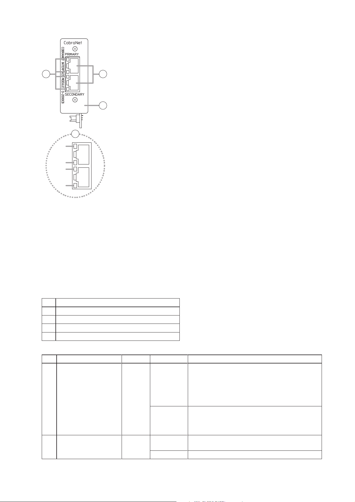
2.4.18. D-2000CB CobraNet Interface Module
29. CobraNet terminals [PRIMARY/SECONDARY]
Terminals used for CobraNet connection. Connect with the commercially available CobraNet device via a
switching hub.
Connect the Primary and Secondary terminals to each single switching hub or two cascade-connected
switching hubs.
Notes
• Be sure to connect both the Primary and Secondary terminals to a switching hub.
• After connection completion, press the D-2008SP's front-mounted Reset switch to restart the D-2008SP.
• Concerning a switching hub, contact TOA dealer.
30. Indicators
31. Panel
30
29
31
30
(a)
(b)
(c)
(d)
LED name
LED Name
PRIMARY operation/CONDUCTOR indicator
(a)
(b)
PRIMARY LINK/ACT indicator
(c)
SECONDARY operation/ CONDUCTOR indicator
(d)
SECONDARY LINK/ACT indicator
Detailed function
LED Function LED color LED status System status
Operation/CONDUCTOR
indicator
(a)
(c)
LINK/ACT indicator Green Flashing or lit
(b)
(d)
Orange Flashing or lit
Unlit
Unlit
CobraNet operation
Flashing: Conductor
Lit: Performer
Note
One of the PRIMARY and SECONDARY indicators
flashes or lights.
Not operating
Note
Both of the PRIMARY and SECONDARY indications
could not go out at a time.
Link to the switching hub, or data transmission and
reception
Unconnected
Page 27

27
Note
Never touch the parts on the
circuit board.
3. INSTALLATION
3.1. Inserting the D-2000CB
To prevent a fire or electric shock, never open nor remove the unit
case, as there are high voltage components inside the unit. Refer all
servicing to qualified service personnel.
WARNING
Step 1. Remove the D-2008SP's power plug from an AC wall outlet.
Never do this work with the power cord connected to the AC
outlet, as doing so may cause electric shock.
WARNING
Step 2. Remove 8 blank panels by unscrewing
16 screws on the D-2008SP's rear panel.
Step 3. Remove the blank panel covering the
CobraNet interface module slot by
unscrewing 2 screws on the D-2008SP's
rear panel.
The removed screws are not used.
Be sure to install the D-2000CB first before inserting other modules into the slots.
D-2008SP
Connector
Blank panel
Blank panels
D-2008SP
Screw post (female)
2
23
3
4
Machine screw M3 x 8
D-2000CB
5
6
Machine screw M3 x 8
(supplied with the D-2000CB)
Connector
Page 28

28
Step 7. Secure the panel to the CobraNet interface
module slot section with 2 screws.
Ensure that 2 connectors of the D-2000CB
project from the rectangle hole in the panel
before tightening screws.
[Installing the input, output, and control modules]
After mounting completion of the D-2000CB, install
other modules with the removed screws that held the
blank panels.
Further, replace the removed blank panels to the idle
slots.
Terminal pins of the connector are exposed on the solder side of
the D-2000CB board. Never touch these terminal pins when
inserting the connector to prevent finger injury.
CAUTION
Step 6. Secure the D-2000CB to the inside of the D-2008SP with 1 screw.
Note
Be sure to secure the D-2000CB with the screw.
Doing otherwise may cause its connector to be disconnected, resulting in malfunction.
Step 4. Remove the D-2000CB's panel.
Note: The removed 2 screws are used in step 7.
Step 5. Insert the D-2000CB's connector into the D-2008SP's internal connector.
D-2008SP
D-2000CB's connector
D-2000CB
7
Panel
(removed in step 4)
Machine screw M3 x 8
(removed in step 4)
Page 29

29
3.2. Rack Mounting
Notes
• To achieve sufficient ventilation, be sure to mount a perforated panel larger than 1U size* above and below
the unit.
• Do not position the heat-generating component such as a power amplifier immediately below the D-2008SP
in the rack even if the perforated panel is mounted between them. Also, keep such components away from
each other so that the ambient temperature around the D-2008SP should not exceed +40 ºC (104 ºF).
Failure to do so may shorten the product life.
* 1U size = 44.5 mm or 1.75" (standard size)
3.2.1. D-2008SP
(When rack mounting screws are supplied)
The supplied rack-mounting screws can be used for the TOA equipment
rack only. Do not use them for other racks.
When installing the unit in a rack other than that of TOA, be sure to use
the screws with a diameter of over 5 mm
(0.2")
and length of over 12 mm
(0.47")
to mount the unit.
Failure to do so may cause personal injury.
(When rack mounting screws are not supplied)
Rack mounting screws are not supplied with the unit.
Be sure to use the screws with a diameter of over 5 mm (0.2") and length
of over 12 mm (0.47") to mount the unit.
Failure to do so may cause personal injury.
CAUTION
D-2008SP
D-2008SP
Perforated panel
(with ventilation slots)
Page 30

30
Notes
• To achieve sufficient ventilation, be sure to mount a perforated panel larger than 1U size* above the unit.
• Do not position the heat-generating component such as a power amplifier immediately below the D-2012C in
the rack. Also, keep such components away from each other so that the ambient temperature around the D2012C should not exceed +40 ºC. Failure to do so may shorten the product life.
* 1U size = 44.5 mm or 1.75" (standard size)
3.2.3. D-911
3.2.2. D-2012C
D-2012C
Perforated pane
(with ventilation slots)
D-2012C
D-911
Page 31

31
3.3. When Installing the D-2012C on a Desk
Attaching the D-2012AS Console Case to the D-2012C allows the D-2012C to be used on a desk.
3.3.1. Components of the D-2012AS Console Case
3.3.2. Attaching the D-2012AS Console Case
Step 1. Remove 3 screws on each side of the D-2012C to detach the rack mounting brackets.
The removed screws are not used.
Step 2. Attach the 4 rubber feet to the bottom surface of the
D-2012C using the 4 supplied screws.
Be sure to attach the rubber feet, as the air vents
are provided at the bottom surface.
* Component parts of the D-2012AS.
Machine screw M4 x 10:
4 pieces
Side panel L
Side panel R
Decorative panels
Armrest
Machine screw
M4 x 25 (with washer):
11 pieces
Rubber foot: 4 pieces
Rack mounting bracket
D-2012C
Machine screw
M4 x 10*
Rubber foot*
Page 32

32
Step 3. Attach the side panel L to the left side of the D-2012C and side panel R to its right side with 2 each
screws.
Step 4. Fit each decorative panel into the holes on the side panels L and R, then secure them with 2 each
screws from the side panels inside.
Step 5. Attach the armrest to the D-2012C's front panel with 3 screws.
* Component parts of the D-2012AS.
Decorative panel*
3
Machine screw M4 x 25
(with washer)*
Side panel L*
Machine screw M4 x 25
(with washer)*
Machine screw
M4 x 25
(with washer)*
4
Armrest*
Side panel R*
[Finished assembly]
Page 33

33
4. CONNECTION
4.1. Connection Example 1
AMX, Crestron, or other
control equipment
BGM player (Cassette deck, CD
player, MD player, etc.)
D-971M D-2000DA1
REMOTE CONTROL MODULE model D-981
C
1
2
3
4
INPUT
5
6
7
8
C
C
1
2
3
4
OUTPUT
5
6
7
8
C
LINE OUTPUT MODULE
[+4 dB]
model D-971M
D-981
1
2
3
4
1
: E
: H
2
: C
3
LINE OUTPUT MODULE [–10/+4 dB] model D-2000DA1
Microphone
MIC/LINE INPUT MODULE [–50
1
2
3
4
1
: E
: H
2
: C
3
1R2R1L
2L
/
–36
/
–10
/
3L3R
+4 dB]
4L4R
model D-936RSTEREO SELECT INPUT MODULE [ –10 dB]
model D-2000AD1
MIC/LINE INPUT MODULE [–50
1
2
/
–36
/
–10
/
+4 dB]
3
model D-2000AD1
4
2
: H
1
3
: E
: C
1
2
3
4
2
: H
1
3
: E
: C
D-2000AD1D-936R
PC
Switching hub
D-2012C
Remote controller
Speaker
Power amplifier
Speaker
Page 34

34
4.2. Connection Example 2
BGM player (Cassette deck, CD player, MD player, etc.)
D-2008SP
PC
Switching hub
REMOTE CONTROL MODULE model D-981
REMOTE CONTROL MODULE model D-981
C
1
2
3
4
INPUT
5
6
7
8
C
C
1
2
3
4
OUTPUT
5
6
7
8
C
Power amplifier
C
1
2
3
4
5
6
7
8
C
C
1
2
3
4
5
6
7
8
C
INPUT
OUTPUT
LINE OUTPUT MODULE
[+4 dB]
model D-971M
D-2000DA1
LINE OUTPUT MODULE [–10/+4 dB] model D-2000DA1
1
2
3
4
1
: E
: H
2
: C
3
D-2000AD1D-936RD-971MD-981
MIC/LINE INPUT MODULE [–50
1
2
3
4
1
: E
: H
2
: C
3
1R2R1L
2L
/
–36
/
–10
/
3L3R
+4 dB]
4L4R
model D-936RSTEREO SELECT INPUT MODULE [ –10 dB]
model D-2000AD1
MIC/LINE INPUT MODULE [–50
1
2
/
–36
/
–10
/
+4 dB]
3
model D-2000AD1
4
:E
:H
:C
1
2
3
4
:E
:H
:C
Remote controller
Main speaker (R)
Main speaker (L)
Microphone
Remote controller
Speaker Speaker
D-2012C D-2012C
Microphone
Zone A Zone B
Page 35

35
4.3. Removable Terminal Plug Connection
Notes
• Avoid soldering stranded or shielded cable, as contact resistance may increase when the cable is tightened
and the solder is crushed, possibly resulting in an excessive rise in joint temperatures.
• When connecting 2 cables or a shielded cable to a single terminal,
use a ferrule terminal with an insulation sleeve to crimp the cables
because such cable conductors could become loose.
Recommended ferrule terminals for signal cables
(made by Phoenix Contact)
Recommended ferrule terminals for power supply cables
(made by Phoenix Contact)
Crimping tool: CRIMPFOX UD6-4 (made by Phoenix Contact)
Wiring procedures
Step 1. Wiring the supplied removable terminal plug.
1-1. Loosen the terminal screws to insert the wire.
1-2. Tighten the terminal screws.
Ensure that the wire does not break free when
pulled. If the wire does pull free, repeat the
connection procedure from the start.
Step 2. Insert the wired terminal plug into the
corresponding terminal block in the unit's rear
panel.
Note
Do not reverse Steps 1 and 2 above. Force is applied
to the connected receptacle pins while tightening the
terminal screw and they may be damaged, resulting in
bad connector contact.
Cable sheath to trim
* Expose 8 mm (0.31'') or more when using
the above ferrule terminal, and cut off an
extra conductor protruding from the sleeve.
Model Number a l
AI 0,34-8 TQ
AI 0,5-8 WH
2 (0.08)
2.5 (0.1)
0.8 (0.03)
1.1 (0.04)
b
12.5 (0.49)
14 (0.55)
Unit: mm (in)
1
2
l
8 (0.31)
8 (0.31)
Insulation sleeve
a
Contact section
2
l
1
l
bb
Model Number a
AI 1,5-8 BK
AI-TWIN 2 x 1,5-8 BK
a
3.4 (0.31)
1
6.6 (0.26)
2
a
3.6 (0.14)
b
1.8 (0.07)
Solid cable and stranded cable
7 mm*
(0.28'') (0.28'')
Shielded cable
7 mm*
15 mm
(0.59'')
Unit: mm (in)
1
l
14 (0.55)
16 (0.63)2.3 (0.09)
Terminal screw
8 (0.31)
8 (0.31)
Tightens
Insulation sleeve
1
a
2
l
2
a
Slotted screwdriver
Loosens
Removable terminal plug
Contact section
2
l
1
l
Tip
Recommended slotted screwdriver type:
Screwdriver with blade that is 3 mm (0.12'') in width
Bit shape 3 mm
(0.12'')
Page 36

36
4.4. Connecting the Monitor Bus Terminal of the D-2008SP and D-2012C
When using the D-2012C's Line input terminal or headphone jack, connect the D-2012C's Monitor bus
terminal to the Monitor bus terminal on the D-2008SP.
Notes
• Set the identical ID number for the D-2008SP and D-2012C to be connected through monitor bus terminals.
Use the D-2000 Setting Software to set the ID number.
• If D-2008SP Console Setting is performed using the D-2000 Setting Software, the D-2008SP can be set to
receive audio signal from the D-2012C's line input terminal. If D-2012C Function Setting is set, the D2012C's monitor channel output can also be monitored with headphones.
Additionally, if the D-2008SP's output channel is set to "Monitor," output from the monitor channel selected
at the D-2012C can also be output to the D-2008SP's output channel.
D-2008SP
Category 5 or higher shielded
twisted pair cable for LAN
(with RJ45 connectors)
D-2012C
Monitor bus terminals
Page 37

37
4.5. Audio Monitor Line Connection When Multiple Units Are Connected
Connecting multiple D-2008SP units through monitor input and output terminals allows audio signals other
than that of the main unit to be monitored.
[Connection Example]
Notes
• Set the identical ID number for the D-2008SP and D-2012C to be connected through monitor bus terminals.
Use the D-2000 Setting Software to set the ID number.
• Insert the audio module used for monitor input into one of Slots 5 – 8.
• Neither the D-936R Stereo input module nor D-937SP Digital input module can be used as a monitor input.
• When using the D-922F and D-922E Microphone/Line input module as monitor inputs, set the "PHANTOM"
switch to "OFF" and "Input sensitivity" to "+4 dB (LINE)."
• The headphones connected to the D-2008SP can only monitor audio signals from the channels of this D-
2008SP.
Speaker
Power amplifier
Note:
Audio signals of the
D-2008SP units with
ID1 and ID2 only can
be monitored
D-2008SP
(ID1)
Slot 3: D-2000DA1
Slot 4: D-2000DA1
Slot 5: D-2000AD1
Slot 8 Slot 1345
Monitor input
D-2012C (ID 1)
Monitor output 1
Monitor output 2
D-2008SP
(ID 2)
Monitor input
D-2008SP
(ID 3)
Monitor output 2
Monitor output 1
Switching hub
Slot 8 Slot 15
Slot 5: D-2000AD1
Slot 8: D-2000DA1
Slot 7: D-2000AD1
Slot 8 Slot 17
Monitor input
Monitor input
Monitor bus
Monitor bus
Monitor bus
D-2012C (ID 2)
D-2012C (ID 3)
Note:
Audio signals of the
D-2008SP units with
ID1 through ID3 can
be monitored.
Note:
Audio signals of the
D-2008SP units with
ID1 and ID3 only can
be monitored.
Page 38

38
4.7. D-911 Connection
Connect the D-911 to the D-984VC VCA Control Module installed in the D2008SP.
Connect each of eight terminals to the D-984VC's terminal of the same
name by way of the fully-connected straight cable as shown on the right.
4.6. D-2012C's AC Power Cord Connection
To prevent the AC power cord from accidentally coming off, secure it with the supplied cable clamp as shown
below.
D-2012C
Connection panel
Machine screw
M3×6 (accessory)
Cable clamp
(accessory)
Screw hole
D-984VC
Power cord
(accessory)
[Connection]
1
2
3
4
5
6
7
8
1
2
3
4
5
6
1 – 81 – 8
7
8
Control Input terminal 1 – 4
Control Input terminal 5 – 8
Control Output terminal 1 – 4
Control Output terminal 5 – 8
E
F
G
H
CTRL IN IN CH
1-4
5-8
1-4
model D-984VCVCA CONTROL MODULE
5-8
CTRL OUT OUT CH
VCA
1-6
7-12
CONTROL UNITS FOR D-901 ONLY
Input channel VCA terminal 1 – 6
A
Input channel VCA terminal 7 – 12
B
Outnput channel VCA terminal 1 – 4
C
Outnput channel VCA terminal 5 – 8
D
1-4
5-8
D-911
A B C D
E F G H
Page 39

39
4.8. D-984VC Specifications
The optional VCA Fader Unit D-911 can remotely control the VCA Control Module D-984VC.
However, You can make a special unit having the same functions as the D-911 referring to the technical
information described here.
4.8.1. Connection cable and pin arrangements of each terminal
• For connecting to each terminal, use a CAT5 (Category 5) UTP cable fitted with RJ45 connectors at both
ends.
Note
Use a STP cable in an environment where the cable is susceptible to noises.
• Maximum cable length is 100 m.
• Pin arrangement of the D-984VC's terminals
4.8.2. Input and output channel VCA controls (1) – (4)
• With 5 V at an input channel VCA pin (IN CH 1 – 12) or at an output channel VCA pin (OUT CH1 – 8), the
corresponding channel's sound volume is minimum. With 0 V, the sound volume is at the level set by the D2008SP.
• Use 10 kΩ potentiometers of taper B.
• Up to 6 volume controls can be connected to each V pin.
[Connections to the input channel VCA terminal]
D-984VC
VCA
CTRL IN IN CH
1-4
1-6
5-8
7-12
1-4
1-4
model D-984VCVCA CONTROL MODULE
5-8
5-8
CTRL OUT OUT CH
Control input
terminals
CONTROL UNITS FOR D-901 ONLY
Input channel
VCA terminals
Output channel
VCA terminals
Control output
terminals
[Input channel VCA terminals] [Output channel VCA terminals]
Pin No.
1
2
3
4
5
6
7
8
1 – 6
IN CH 1
IN CH 2
IN CH 3
IN CH 6
IN CH 5
IN CH 4
V
C
IN CH
7 – 12
IN CH 7
IN CH 8
IN CH 9
IN CH 12
IN CH 11
IN CH 10
V
C
Pin No.
1
2
3
4
5
6
7
8
OUT CH 1
OUT CH 2
OUT CH 3
OUT CH 4
1 – 4
C
V
V
C
OUT CH
5 – 8
OUT CH 5
OUT CH 6
OUT CH 7
C
V
OUT CH 8
V
C
1 2 3 4
[Control input terminals] [Control output terminals]
Pin No.
1
2
3
4
5
6
7
8
1 – 4
CTRL IN 1
C
CTRL IN 2
C
CTRL IN 3
C
CTRL IN 4
V
CTRL IN
5 – 8
CTRL IN 5
C
CTRL IN 6
C
CTRL IN 7
C
CTRL IN 8
V
Pin No.
1
2
3
4
5
6
7
8
CTRL OUT 1
CTRL OUT 2
CTRL OUT 3
CTRL OUT 4
1 – 4
C 1
C 3
C 2
C 4
CTRL OUT
5 – 8
CTRL OUT 5
C 5
CTRL OUT 6
C 7
CTRL OUT 7
C 6
CTRL OUT 8
C 8
5 6 7 8
1 IN CH 1
2 IN CH 2
3 IN CH 3
D-2008SP's volume
Minimum level
0 V
+5 V
RJ45
4 IN CH 6
5 IN CH 5
6 IN CH 4
7 V (+5 V)
8 C (GND)
D-984VC
[IN CH 1 – 6]
Page 40

40
[Connections to the output channel VCA terminal]
4.8.3. Contact controls (5) – (8)
• Preset memory recall function is assigned to the contact input and output pins at the factory. To change this
function assignment to give channel ON/OFF or stereo input selection, refer to the separate Setting
Software Instructions .
• The V pins of the control input terminals (5) and (6) can be used for LED connections. To do this, connect
the contact COM pins to use out of the C1 – 4 pins of the control output (7) or the C5 – 8 pins of the control
output (8) to the C pins of the control input (5) or (6). (The diagram below is an example where the control
output's C1 – 4 pins are connected to the control input's C pins.)
• The current capacity is 40 mA per V pin. When more current is needed, connect a power supply separately
as shown below.
• Never connect the V pins of control inputs (5) and (6) to the V pins of VCA pins (1) – (4) as the sound
volume may be affected due to voltage drop caused by these connections.
D-2008SP's volume
0 V
RJ45
1 OUT CH 1
2 OUT CH 2
3 OUT CH 3
4 C (GND)
5 V (+5 V)
6 OUT CH 4
7 V (+5 V)
8 C (GND)
D-984VC
[OUT CH 1 – 4]
Minimum level
+5 V
1 CTRL IN 1
2 C (GND)
3 CTRL IN 2
RJ45
RJ45
4 C (GND)
5 CTRL IN 3
6 C (GND)
7 CTRL IN 4
8 V (+5 V)
1 CTRL OUT 1
2 C1
3 CTRL OUT 2
4 C2
5 CTRL OUT 3
6 C3
7 CTRL OUT 4
8 C4
D-984VC's control
input terminal (5)
[CTRL IN 1 – 4]
D-984VC's control
output terminal (7)
[CTRL OUT 1 – 4]
1 CTRL IN 1
2 C (GND)
3 CTRL IN 2
4 C (GND)
5 CTRL IN 3
6 C (GND)
7 CTRL IN 4
8 V (+5 V)
D-984VC's control
input terminal (5)
[CTRL IN 1 – 4]
RJ45
1 CTRL OUT 1
2 C1
3 CTRL OUT 2
DC
4 C2
5 CTRL OUT 3
6 C3
7 CTRL OUT 4
8 C4
D-984VC's control
output terminal (7)
[CTRL OUT 1 – 4]
RJ45
Page 41

41
4.9. Ferrite Cable Clamp Attachment (For D-972AE only)
To reduce electromagnetic noise, place the supplied ferrite clamp over each digital output cable when making
a cable connection to the D-972AE Digital Output Module.
Install one ferrite clamp per digital output cable.
DIGITAL OUT
1/2
AES/EBU
Loop the cable one turn.
Ferrite clamp
(Supplied with the D-972AE)
3/4
model D-972AEDIGITAL OUTPUT MODULE
AES/EBU
D-972AE
Page 42

42
4.10. System Expansion Using CobraNet Connection
4.10.1. CobraNet connection outline
The system can be expanded by inserting the D-2000CB CobraNet Interface Module into the D-2008SP and
connecting it to other CobraNet equipment.
Connect the D-2000CB to other CobraNet equipment via a switching hub.
Connect each of CobraNet Primary and Secondary ports of the D-2000CB to the same switching hub or
different switching hubs connected in cascade.
Notes
• Make the CobraNet terminals completely independent from other LAN.
• The distance between each of D-2000CB modules and the switching hub is less than 100 m.
• Be sure to make connections of both terminals PRIMARY and SECONDARY.
• Audio signals may be interrupted temporarily at the time of switching between PRIMARY and SECONDARY
ports.
• When connecting CobraNet terminal PRIMARY or SECONDARY to multiple switching hubs, be sure to
connect the hubs in cascade.
• Up to 7 switching hubs can be connected in cascade. The number of switching hubs between the D-2000CB
and all CobraNet devices connected to the D-2000CB should be 7 or less. (Refer to connection examples 1
and 2 on the next page.)
• When using multiple switching hubs, making star connection at the hub directly connected to the D-2000CB
as shown in Connection example 2 is highly recommended to reduce the number of cascade-connected
hubs.
D-2008SP
D-2000CB
CobraNet terminal (PRIMARY)
CobraNet terminal (SECONDARY)
Page 43

43
[Connection example 1: Redundant configuration of switching hubs]
As shown in the example above, when the CobraNet unit A is operating via the CobraNet PRIMARY and the
CobraNet unit B is operating via the CobraNet SECONDARY, 6 switching hubs are used for communications
between both units. Therefore, in a redundant configuration of switching hubs*, the number of hubs cascadeconnected from the D-2000CB should be 3 or less.
* A method of connecting a single unit's CobraNet PRIMARY and SECONDARY terminals to each different
switching hub to prevent the system from going down when a cable is broken or power fails.
[Connection example 2: Non-redundant configuration of switching hubs]
As 7 switching hubs are on the communication path from the CobraNet unit A to the CobraNet unit B, there is
no problem for the system. However, as the number of hubs from the CobraNet unit A to the CobraNet unit C
is 8, there may be a system failure.
D-2000CB
CobraNet PRIMARY CobraNet SECONDARY
3
SW-HUB SW-HUB
SW-HUB SW-HUB
2
SW-HUB SW-HUB
1
CobraNet PRIMARY
(Operating)
CobraNet
PRIMARY
CobraNet unit A
CobraNet unit B
CobraNet
SECONDARY
CobraNet
SECONDARY
(Operating)
4
5
6
D-2000CB
CobraNet PRIMARY, SECONDARY
Star connections
3
2
1
SW-HUB SW-HUB SW-HUB
CobraNet unit A
SW-HUB
SW-HUBSW-HUB SW-HUB SW-HUB
SW-HUBSW-HUB SW-HUB SW-HUB
4
5
6
7
CobraNet unit B
SW-HUB
8
CobraNet unit C
Page 44

44
4.10.2. Redundant configuration of switching hubs
In the connection example below, the CobraNet PRIMARY and SECONDARY terminals of each unit are
individually connected to different switching hubs. Even if any one of the switching hubs fails or Main line
breaks, the system is kept operating using another Main line, thus preventing system down.
Notes
• Cycle the entire system's power after connection completion.
• Perform spanning tree setting within switching hubs. For the settings, refer to the instruction manual of the
switching hub.
• Audio signals may be interrupted temporarily at the time when the network configuration automatically
changes due to failure of any switching hub or disconnection of the main line.
• Contact your TOA dealer for more information on switching hubs.
Category 5 or higher shielded
twisted pair cable for LAN
Main line
D-2008SP
PRIMARY
SECONDARY
(with RJ45 connectors)
To other
switching hub
Switching hub
(PRIMARY-1)
Switching hub
(PRIMARY-2)
To other
switching hub
D-2008SP
D-2008SP
D-2008SP
CobraNet unit
PRIMARY
SECONDARY
PRIMARY
SECONDARY
PRIMARY
SECONDARY
To other
switching hub
Switching hub
(SECONDARY-1)
Main line
Switching hub
(SECONDARY-2)
To other
switching hub
PRIMARY
SECONDARY
Main line
Page 45

45
4.10.3. Non-redundant configuration of switching hubs
In the connection example below, both CobraNet PRIMARY and SECONDARY terminals of each unit are
connected to the same switching hub.
Notes
• Cycle the entire system's power after connection completion.
• Contact your TOA dealer for more information on switching hubs.
D-2008SP
PRIMARY
D-2008SP
D-2008SP
SECONDARY
PRIMARY
SECONDARY
PRIMARY
SECONDARY
Category 5 or higher shielded
twisted pair cable for LAN
(with RJ45 connectors)
Switching hub
D-2008SP
CobraNet unit
PRIMARY
Switching hub
SECONDARY
PRIMARY
SECONDARY
Page 46

46
4.10.4. Largest-scale system connection example
D-2008SP: Up to 4 units (Up to 128 inputs/outputs*)
D-2012C: Up to 4 units
PC: 1 unit
D-911: Up to 8 units (The D-984VC VCA control module must be inserted into the D-2008SP.*)
* Control module cannot be used in a system of 128 audio input/output channels. The maximum number of
audio input/output channels decreases to 96 when 8 D-911 units are connected.
Zone A Zone B
D-2008SP
D-2012C
PC
D-911
D-911
LAN CobraNet
D-2008SP
D-2012C
D-911
D-911
CobraNet unit
D-2008SP
D-2012C
D-911
D-911
Zone C Zone D
D-2008SP
D-2012C
D-911
D-911
Page 47

47
5. PC CONNECTIONS
Connect a PC, the D-2008SP, and the D-2012C to a switching hub using LAN straight cables individually.
D-2008SP
Switching hub
LAN connection
terminal
PC
D-2008SP
LAN connection
terminal
D-2012C
D-2012C
Category 5 or higher shielded
twisted pair cable for LAN
(with RJ45 connectors)
LAN connection
terminal
LAN connection
terminal
Page 48

48
6. RETURNING SETTINGS TO THEIR INITIAL FACTORY DEFAULT
(D-2008SP ONLY)
Step 1. Turn off the power.
Step 2. Turn on the power while holding down the
Selection keys " " and " ." Release all the
keys when the "in" indication appears on the
Number display.
Step 3. Press the Set key when the "in" indication
begins to flash.
All setting items return to their initial factory
settings.
Note
For the factory default settings, refer to the
separate Setting Software Instructions.
Note
The D-2012C has no parameters to be initialized.
D-2008SP
Keys and switch used in operation
2
Power switch
Selection keys
Number display
Flashing
3
Set key
Page 49

49
7. FIRMWARE UPDATE PROCEDURE (D-2012C ONLY)
Only when updating the D-2012C firmware ver. 2.0.0, follow the procedure below using the dedicated "D2012C Firmware Updater Software Program*."
* Included in the CD supplied with the D-2008SP firmware version 3.0.0 or later.
Note
When the D-2012C firmware version is 3.0.0 or later, update can be performed using the Setting software via
a LAN.
D-2012C firmware version can be checked in the connection setting in the Setting software. For details, refer
to the separate Software setting instruction.
Step 1. Connect both RS-232C ports of the D-2012C and the PC using a 9-pin straight through cable (male-
to-female cord).
Step 2. Insert the CD supplied with the D-2008SP into the PC's CD drive.
Step 3. Double-click "English - D2000_Software - d2012c _update _200 _to_300.exe" in the CD.
"D-2012C Firmware Updater software" activates.
4
6
Step 4. Click the [ComSetting] button.
The ComSetting screen appears.
5
5
D-2012C
9-pin straight through cable
(male-to-female cord)
RS-232C terminal
PC
Page 50

50
Step 5. Set the PC's Com port the D-2012C is connected to, and click [OK] button.
The ComSetting screen closes.
Note: Set the "Speed" to 115200.
Step 6. Click the [Update] button of the D-2012C Firmware update screen.
The firmware update starts being transferred from the PC to the D-2012C.
The following screen appears after the update ends.
[If "No Reply" is displayed]
If the screen on the right appears after clicking the
[Update] button, confirm the following:
• RS-232C cable specification and connection
Check that 9-pin straight cable (male - female) is
used.
• PC communication settings (Step 4)
After confirming all the above items, follow the
procedure from Sep 3 again.
If the same "No Reply" indication still appears in this
Step 6, turn the D-2012C's power off, and on again.
Then, follow the steps again from the beginning.
Step 7. Turn the D-2012C's power off, and on again.
Step 8. Click the [Exit] button to end the firmware update.
Page 51

51
8. OPERATIONS
8.1. D-2008SP Operation
Using the front panel-mounted keys, preset memories can be recalled, and input or output channel to be
monitored can be selected.
Input or output channel can be monitored through headphones connected to a front panel-mounted
headphone jack. Its output sound can be adjusted with a front panel-mounted headphone volume control
knob.
For the channel with stereo link established, it can be monitored in stereo.
For the channel in monaural, the same audio signal is provided to the left and right headphone speakers.
Section used in operation
Monitor number
Monitor Selection
Indicator
D-2008SP
Headphone jack Headphone volume control knob
Item selection indicators
(PRESET,
MONITOR,
CONSOLE,
CobraNet)
Set key
Number display
Selection keys
Page 52

52
8.1.1. Recalling preset memories
Follow the procedure below to recall each parameter setting stored as preset memory* using the D-2000
Setting Software or D-2012C Remote console unit.
Note
When multiple D-2008SP and D-2012C units are installed in the system, the D-2008SP with ID1 must be
included to simultaneously operate other units in the system through the following operation.
Step 1. Press the Selection key " " or " " several times to light
"PRESET" (Item selection indicator).
Preset memory Number is displayed on the Number
display.
Step 2. Press the Selection key " " or " " to select preset
memory Number (1 – 32).
During this period, the number displayed on the Number
display is flashing.
Step 3. Press the Set key to confirm the preset memory Number.
When confirmed, the displayed Number changes from
flashing to steady-on state, and the parameters stored
under its preset memory number is recalled.
* Parameters stored in preset memory are as follows:
Input channel parameters: PAD, phantom power, line input mode selection, line input selection, input trim
gain, input trim polarity, input filter, compressor / auto leveler mode selection,
compressor / auto leveler, level sensibility, gate, auto mixing function group,
ducker, NOM attenuation function ON/OFF, input channel gain, channel
ON/OFF, and group trim gain
Bus channel parameters: Feedback suppression (dynamic mode ON/OFF, settings of the number of
filters, and filter value set in auto mode and dynamic mode), sub-in-mix-gain,
sub-in-mix ON/OFF, bus channel gain, channel ON/OFF, and group trim gain
Output channel parameters: Output channel gain, group trim gain, channel ON/OFF, filter (including
crossover), compressor, delay time, and mute
Others: Stereo link setting, crossover function configuration setting, NOM attenuation
function setting, and matrix assignment
PRESET
Lights
Flashing
Steady-on
Page 53

53
8.1.2. Selecting the input or output channel to be monitored
D-2008SP's input or output channels in operation can be monitored.
Step 1. Press the Selection key " " or " " several times to light
"MONITOR" (Item selection indicator).
Step 2. Press the Selection key " " or " " to select monitor
number (1 – 32).
The monitor selection indicator of the selected number
lights.
Note: Idle channel is skipped.
Monitor Numbers are assigned in groups of 4 to each
module slot as shown below.
Idle channels will result if no module is installed in a slot
or if a single 2-channel module is installed (in this case,
the remaining 2 channels become idle).
Step 3. Connect headphones to the headphone jack, then adjust the sound volume with the headphone
volume control knob.
MONITOR
Lights
D-2008SP rear
Monitor number
Lights
12345678
1 – 45 – 89 – 1213 – 1617 – 2021 – 2425 – 2829 – 32
Slot number
Monitor number
indicated channels
Rear's
slot number
D-2008SP front
1234 5 768
Page 54

54
Step 3. Connect headphones to the headphone jack, then adjust the sound volume with the headphone
volume control knob.
8.1.3. Selecting the D-2012C's monitor channels
The line input and headphone output of the D-2012C Remote Console connected to the D-2008SP
processor's Monitor bus terminal can be monitored.
Note
Before selecting, connect the D-2008SP's Monitor bus terminal to the D-2012C's Monitor bus terminal and
perform console settings using the D-2000 Setting Software.
Step 1. Press the Selection key " " or " " several times to light
“CONSOLE” (Item selection indicator).
Step 2. Press the Selection key " " or " " to select monitor
number (1 – 4).
The monitor selection indicator of the selected number
lights.
Monitor numbers 1 and 2 respectively correspond to the
D-2012C's Line inputs L and R, while monitor numbers 3
and 4 correspond to the D-2012C's Headphone outputs
L and R.
D-2012C
Monitor number
indicated channels
CONSOLE
Lights
Lights
Monitor number
Line L: 1
Line R: 2
D-2008SP front
Headphone output L:
Headphone output R:34
Page 55

55
8.1.4. Selecting CobraNet's monitor channels
When the D-2000CB CobraNet Interface Module has been inserted into the D-2008SP and connected to other
CobraNet equipment, CobraNet's input and output channel preprogrammed using the D-2000 Setting
Software can be monitored.
Step 1. Press the Selection key " " or “ " several times to light
"CobraNet" (Item selection indicator).
Step 2. Press the Selection key " " or " " to select monitor
number (1 – 32).
The monitor selection indicator of the selected number
lights.
Note: Idle channel is skipped.
Monitor numbers correspond as follows to the D-2008SP
input and output channels set in the D-2000 Setting
Software bundle settings:
Step 3. Connect headphones to the headphone jack, then adjust the sound volume with the headphone
volume control knob.
Monitor number
CobraNet
Lights
Lights
CobraNet input
and output
D-2008SP
Input
(A channel 1 – 8)
Input
(B channel 1 – 8)
Output
(A channel 1 – 8)
Output
(B channel 1 – 8)
Page 56

56
K
K
8.1.5. Key lock function ON/OFF
Enabling the key lock function disables the following operations made on the D-2008SP's front panel.
• Recalling preset memories
• Selecting the input or output channel to be monitored
• Selecting the D-2012C's monitor channels
• Selecting CobraNet's monitor channels
[Setting the key lock function to ON]
Hold down the Set key for approximately 5 seconds while the Key
Lock indicator is unlit.
The Key Lock indicator then lights, enabling the key lock function.
[Setting the key lock function to OFF]
Hold down the Set key for approximately 5 seconds while the Key
Lock indicator is lit.
The Key Lock indicator goes out, disabling the key lock function.
D-2008SP
Enabling the key lock function disables
the left and right key operation.
KEY LOC
Lights
Hold down for approximately 5 seconds.
KEY LOC
Goes out
Hold down for approximately 5 seconds.
Page 57

57
8.2. D-2012C Operation
8.2.1. Key-assignable functions
The following functions can be assigned to the D-2012C's function keys. The function keys are explained on
the following pages using the name of the function assigned to each key (example: Memory key).
Note
To implement the following functions (except Stereo Input) with the function key operation, the D-2008SP with
ID1 must be included in the system.
• Memory
Recalls the setting status stored in preset memory. The D-2012C's current setting status can be stored in
preset memory by pressing the function key assigned to the memory function in combination with the
function key assigned to the memory storage function. (Refer to p. 58.)
• Memory Store
Press the key assigned to the memory store function in combination with the function key assigned to the
memory function. (Refer to p. 58.)
• Line Input (valid only when the D-936R or D-937SP module is installed)
Switches the line (stereo) input of the D-936R Stereo Input Module or D-937SP Digital Input Module.
(Refer to p. 59.)
• LED Control
Causes the D-2008SP's front panel-mounted level indicator to go out. (Refer to p. 59.)
• Fader Layer
Recalls the channel assignment status stored in the fader layer. (Refer to p. 60.)
• Console Switch
Sets the contact output of the D-981 or D-983 Remote Control Module or the D-984VC VCA Control
Module installed in the D-2008SP processor to ON. (Refer to p. 61.)
• Key Lock
Enables and disables manual operation of the D-2012C's motorized faders, function keys, rotary
encoders, etc. (Refer to p. 62.)
• Monitor Clear
Clears the selection of channels to be monitored. (Refer to p. 63.)
• External Control Switch
Allows the D-2008SP with ID 1 to transmit the function key ON/OFF data to an AMX or other external
control devices using external control protocol. The external control device can transmit the external
control command to the D-2008SP with ID 1, controlling its function key's indicator ON or OFF.
(Refer to p. 61.)
Note
Functions shown in the following figure are assigned by default. To change these assignments, use the D2000 Setting Software supplied with the D-2008SP processor. For details, please read the separate software
setting manual.
[Default Setting]
Memory 4
Memory 3
Memory 2
Memory 1
D-2012C function key section
Memory 5
Memory 6
Memory store
Key lock
Page 58

58
8.2.2. Preset memory recall
Each parameter stored as preset memory using the D-2000 Setting Software or the D-2012C can be recalled.
[Operation]
Pressing the Memory key switches the operation panel settings to the setting status
stored under the designated preset memory number. In this event, the depressed key
lights.
Notes
• Even if the preset memory number switches, the fader layer number remains
unchanged.
• The figure shows an example in which "Memory 1" has been assigned to Function
key 1.
8.2.3. Storage in preset memory
Store the current setting status of each channel in preset memory.
Parameters stored in preset memory are as follows:
[Parameters Stored In Preset Memory]
Input channel parameters: PAD, phantom power, line input mode selection, line input selection, input trim
gain, input trim polarity, input filter, compressor / auto leveler mode selection,
compressor / auto leveler, level sensibility, gate, auto mixing function group,
ducker, NOM attenuation function ON/OFF, input channel gain, channel
ON/OFF, and group trim gain
Bus channel parameters: Feedback suppression (dynamic mode ON/OFF, settings of the number of
filters, and filter value set in auto mode and dynamic mode), sub-in-mix-gain,
sub-in-mix ON/OFF, bus channel gain, channel ON/OFF, and group trim gain
Output channel parameters: Output channel gain, group trim gain, channel ON/OFF, filter (including
crossover), compressor, delay time, and mute
Others: Stereo link setting, crossover function configuration setting, NOM attenuation
function setting and matrix assignment
[Storage]
Continue to press the Memory key for approximately 2 seconds while holding down the Memory Store key.
After the two keys have lit, the Memory key flashes twice and the operation panel's current setting status is
stored in the designated preset memory number.
Note
The figure shows an example in which "Memory 3" has been assigned to Function key 3, and "Memory Store"
to Function key 7.
Memory 1
Lights
Memory 3
Lights
Press for approximately 2 seconds.
Memory
Store
Lights Goes out
Memory 3
Flashes twice
Memory
Store
Page 59

59
8.2.5. D-2008SP level indicator control (LED control)
This function turns off the level indicators on the front panel of the D-2008SP Digital Mixing Processor.
[Operation]
Press the LED Control key, and the D-2008SP's front panelmounted level indicators go out.
In this event, the depressed control key goes out.
Pressing the LED Control key again causes the D-2008SP's
front panel-mounted level indicators to light.
In this event, the depressed control key lights.
Note
The figure shows an example in which "LED control" has been
assigned to Function key 5.
8.2.4. Switching Line Inputs (valid only when the D-936R or D-937SP module is installed)
This function switches the line inputs (In 1 – 4) of the D-936R Stereo Input Module or the D-937SP Digital
Input Module.
[Operation]
Pressing the Line Input key selects the designated line (stereo) input.
In this event, the depressed key lights.
Note
The figure shows an example in which "Line Input (In 4)" has been assigned to Function
key 4.
Line Input 4
D-2008SP
Level indicators
Lights
LED Control
LED Control
Lights
Unlit
LED Control
Goes out
LED Control
Lights
Page 60

60
8.2.6. Fader layer switching
There are 12 motorized faders and 8 rotary encoders on the D-2012C's operation panel. Store a combination
of their channel assignments as a single fader layer in advance using the D-2000 Setting Software. Since 4
different fader layers can be set, up to 4 channels can be assigned to each motorized fader and rotary
encoder. By switching the channel assignment status using the Fader Layer key, up to 80 channels can be
operated in monaural per D-2012C Console. If stereo link and grouping settings are performed, more
channels can be operated.
[Fader Layer Setting Example]
Tip
Bus channels and CobraNet
channels can also be assigned.
[Fader Layer Switching]
Pressing the Fader Layer key switches the operation panel settings to the status stored in
the designated fader layer number. In this event, the depressed key lights.
Notes
• Even if the fader layer number switches, the preset memory number remains
unchanged.
• The figure shows an example in which "Fader Layer 2" has been assigned to Function
key 2.
(Fader layer 1 setting status: Inputs 1 – 12 & outputs 1 – 8)
D-2012C
In 1 – 12
(Fader layer 2 setting status: Inputs 13 – 24 & outputs 9 – 16)
Out 5 – 8 Out 1 – 4
D-2012C
In 13 – 24 Out 13 – 16 Out 9 – 12
Fader Layer 2
Lights
Page 61

61
8.2.7. D-2008SP control output ON/OFF (console switch)
Enables or disables the contact output of the D-981 or D-983 Remote Control Module installed in the D2008SP Digital Mixing Processor. The contact output terminals assigned to the "Console switch" using the D2000 Setting Software can be operated. Operation differs depending on the setting of the contact output
terminal's control method.
Note
Unify the control method of all the contact output terminals assigned to a single console switch to either
"Momentary" or "Latch."
[When the Control Method Is Set to "Momentary"]
The set contact output is enabled as long as the Console Switch key is held down and
the continuously depressed key remains lit. If the Console Switch key is released, the
set contact output is disabled and the depressed key goes out.
[When the Control Method Is Set to "Latch"]
The set contact output is enabled if the Console Switch key is pressed and the
depressed key lights. Pressing the Console Switch key again disables the set contact
output and causes the depressed key to go out.
Note
The figure shows an example in which "Console switch" has been assigned to Function key 6.
8.2.8. D-2008SP (ID 1) external control switch
Allows the D-2008SP with ID 1 to transmit the function key ON/OFF data to an AMX or other external control
devices using external control protocol (RS-232C or LAN).
The external control device can transmit the external control command to the D-2008SP with ID 1, controlling
its function key's indicator ON or OFF.
[Example of control using RS-232C]
[Operation]
When the External Control Switch key is pressed, data that the key has been pressed is transmitted from the
D-2008SP to the external control device using the external control protocol. To light or extinguish the External
Control Switch key's indicator, controls should be made from the external control device using the external
control protocol.
Console
Switch
Lights
D-2008SP (ID 1)
Switching hub
D-2012C
D-2012C function key's
indicator ON/OFF control
D-2012C function key ON/OFF data
RS-232C
AMX or other control devices
Page 62

62
8.2.9. Key lock function ON/OFF
Setting the Key Lock function to ON allows operation of the following keys to be disabled: the D-2012C's
operation panel-mounted function keys (except the Key Lock key), motorized faders, rotary encoders, Monitor
Channel Selection keys, and Channel ON/OFF keys.
[When Enabling the Key Lock Function]
Holding down the Key Lock key for approximately 5
seconds while it is unlit causes the depressed key to
light and enables the Key Lock function. In this event,
the key lock indicator lights. While the Key Lock
function is enabled, any key pressed other than the
Key Lock key does not change status and remains lit
or unlit. If a motorized fader is moved, it returns to its
original position if the fader is released. Also, if a rotary
encoder is rotated, the LEDs that indicate volume do
not change.
[When Disabling the Key Lock Function]
Holding down the Key Lock key for approximately 5
seconds while the Key Lock key is lit causes the
depressed key to go out and disables the Key Lock
function. In this event, the key lock indicator goes out.
Note
The figure shows an example in which "Key lock" has
been assigned to Function key 8.
Key lock indicator
(Lockable operation section) D-2012C
Key Lock Key Lock
When unlit
Lights
(Key Lock function ON)
Press for approximately 5 seconds.
Key Lock Key Lock
When lit
Goes out
(Key Lock function OFF)
Press for approximately 5 seconds.
Lights
Goes out
Page 63

63
8.2.10. Monitor channel clear
This function clears the selection of all the monitor channels assigned to the monitor bus to which the D2012C in operation is connected.
[Operation]
If the Monitor Clear key is pressed, the selection of monitor channels is cleared and the
depressed key lights.
Note
The figure shows an example in which "Monitor clear" has been assigned to Function
key 3.
8.2.11. Monitoring
Output of the channel being operated using the D-2012C Remote Console's motor faders or rotary encoders
can be monitored.
Notes
• Set the identical ID number for the D-2008SP and D-2012C to be connected through monitor bus terminals.
Use the D-2000 Setting Software to set the ID number.
• Properly perform connections and settings for the D-2008SP's monitor input/output channels. (Refer to
p. 37.) Audio signals for the channel where monitor audio signal routing is not performed cannot be
monitored even if selected.
• Monitor channel selection keys do not perform grouping operation.
Step 1. When two or more fader layers are in use, select the fader layer that allows operation of the channel
to be monitored.
Fader layers can be switched through operation of the function key assigned to Fader Layers 1 – 4.
(Refer to p. 60.)
Step 2. Set the Monitor channel selection key for the channel to be monitored to ON.
The level of the selected output can be confirmed by means of the monitor signal indicator.
Step 3. Connect headphones to the Headphone jack and adjust the volume using the monitor volume control
knob.
Monitor Clear
Lights
Monitor channel selection keys
D-2012C
Monitor signal
indicators
Monitor volume
control knob
Headphone jack
Motor faders Rotary encoders
Page 64

64
8.3. D-911 Operation
Only the D-2008SP's channels to which the D-984VC module is connected can be controlled.
8.3.1. Volume adjustment
Volume of the channel assigned to the D-984VC using the D-2000 Setting software can be adjusted using the
D-911’s input fader or output volume control knob.
Notes
• For channels with stereo link or group settings established at the D-2008SP, only the lowest numbered
channel in the preset link or group is enabled.
• Fader position "10" of the D-911 provides the channel gain set by the D-2008SP. As a guide, fader position
"8" provides channel gain about 10 dB lower than the set gain at the D-2008SP.
8.3.2. Contact control
Preset memory recall, Volume level up and down functions can be assigned to the
D-984VC's contacts using the D-2000 Setting Software.
Assigned functions can be implemented by pressing the Control keys 1 – 8.
Control keys
D-911
Input faders Output volume control knobs
Page 65

65
9. BLOCK DIAGRAMS
9.1. D-2008SP
L
L
Microphone/Line Input Module
(D-2000AD1)
+48 V PAD AD
+48 V PAD AD
+48 V PAD AD
+48 V PAD AD
Microphone/Line Input Module
(D-921F or D-921E)
+15 V PAD AD
+15 V PAD AD
Microphone/Line Input Module
(D-922F or D-922E)
+15 V PAD AD
DIP SW
DSP
(See the next page.)
Line Output Module
(D-971M or D-971E)
DA
DA
DA
DA
Line Output Module
(D-2000DA1 or D-971R)
DA
DA
DA
DA
Digital Output Module (D-972AE)
DIT
DIT
DIT
DIT
Stereo Input Module
(D-936R)
L
R
L
R
L
R
L
R
Digital Input Module
(D-923AE)
Digital Input Module
(D-937SP)
OPTICAL
OPTICAL
COAXIAL
COAXIAL
+15 V
PAD AD
DIP SW
Selector
DIR DE-EMP SRC
DIR DE-EMP SRC
Automatic
DIR DE-EMP SRC
Selector
DIR DE-EMP SRC
AD
AD
Automatic
CobraNet Interface Module
(D-2000CB)
CobraNet
Controller
MAC/
PHY
MAC/
PHY
CPU
Digital Output Module (D-961SP)
DIT
DIT
DIT
DIT
OPTICAL
COAXIA
OPTICAL
COAXIA
Remote Control Module (D-981)
IN 1
Control
IN 8
OUT 1
OUT 8
Remote Control Module (D-983)
IN 1
Control
IN 24
OUT 1
OUT 16
VCA Control Module (D-984VC)
VCA
Control
RS-232CUSBLAN
IN CH 1
IN CH 12
OUT CH 1
OUT CH 8
CTRL IN 1
CTRL IN 8
CTRL OUT 1
CTRL OUT 8
Page 66

66
[DSP part block diagram of D-2008SP]
Audio In 1 – (34)
CobraNet In 1 – (16)
From
D-2000CB (A8, B8)
Audio Bus 1 – (24)
Ext. In 1 – (4)
Max. 32
Max. 16
BUS
Delay
FBS
Trim
HPF/
LPF
COMP/
Leveler
Auto mix
PEQ
ON
MONITOR
Fader VCA
Fader
Fader
VCA
Input Matrix
Audio Bus 1
Audio Bus 2
Audio Bus 24
GR Trim
GR Trim
ON
CobraNet Sub In SEND
CobraNet Bus SEND
MONITOR
MONITOR
Fader VCA
GR Trim
GUI
METER
(PFL)
GUI
METER
(PFL)
GUI
METER
(AFL)
LED
METER
LED, GUI
METER
(PFL)
Ext. In
Audio
LED
METER
LED
METER
MONITOR
MONITOR
ON
ON
Fader VCA
GR Trim
GUI
METER
(AFL)
GUI
METER
(PFL)
ON
Fader VCA
GR Trim
GUI
METER
(AFL)
GUI
METER
(PFL)
ON
Sub In Mix
: Only when D-984VC is used
CobraNet Bus 1 – (16)
VCA
Trim
HPF/
LPF
COMP/
Leveler
Auto mix
PEQ
ON
Fader VCA
GR Trim
LED, GUI
METER
(PFL)
MONITOR
Max. 2
MONITOR
Max. 4 (Stereo)
From
Slot 1 – 8
From Slot
Console Line Input
(MONITOR BUS from C-2012C)
MONITOR
Max. 4 (Stereo)
Slot 5 – 8
Max. 4
Page 67

67
(Console MONITOR)
PHONES
MONITOR BUS to D-2012C
Audio Out 1 – (32)
CobraNet Out 1 – (16)
Filter/
X over/
Polarity
Comp Delay
Mute
Mute
GUI
METER
(AFL)
LED, GUI
METER
(TGL)
Max. 32
Max. 16
To
D-2000CB (A8, B8)
To
Slot 1-8
Fader VCA
Output Matrix
Audio Out 1
Audio Out 2
Audio Out 32
CobraNet Out 1
CobraNet Out 2
CobraNet Out 16
MONITOR
BUS
1-L
1-R
HEAD
PHONES
L
R
2-L
4-R
MONITOR
MONITOR
ON
Fader VCA
ON
GR Trim
GR Trim
LED, GUI
METER
(AFL)
MONITOR
LED
METER
MONITOR
Max. 4 (Stereo)
LED
METER
(TGL)
MONITOR
MONITOR
Max. 4 (Stereo)
Page 68

68
9.2. D-2012C
Counter
ROTARY ENCODER
LAN
LINE-INPUT
HEADPHONE
OUTPUT
LEFT
RIGHT
MOTOR
FADER
SWITCH
INPUT
LEVEL
MONITOR
LEVEL
FADER
CPU
SWITCH
SIGNAL PEAK
SIGNAL PEAK
AD
Converter
DA
DIT
DIR
MAIN
CPU
RS-232C
MONITOR
BUS
to D-2008SP
AC
INLET
POWER
SWITCH
POWER
SUPPLY
Converter
+9V
Page 69

69
9.3. D-911
VCA
IN CH 1-6
VCA
IN CH 7-12
VCA
OUT CH 1-4
VCA
OUT CH 5-8
CTRL
IN 1-4
CTRL
OUT 1-4
CTRL
IN 5-8
CTRL
OUT 5-8
DC
DC
DC
DC
Make contact
DC
16
712
14
58
14
14
5 – 8
Same as above
Page 70

70
10. LEVEL DIAGRAMS
10.1. Analog Input/Output
10.2. Digital Input/Output
+20
+10
-
10
-
20
-
30
-
40
-
50
Microphone/Line Input Module
D-921F, D-921E, D-922F,
D-922E, or D-2000AD1,
or
Stereo Input Module D-936R
dBu
Max. Input (+24)
LINE
(+4)
0
LINE
-
10)
(
MIC
(
-
36)
MIC
(
-
50)
DSP
Digital
Clipping Level (+20 dB)
Peak LED Turns ON
(+17 dB)
(0 dB)
Line Output Module
D-971M, D-971E, D-971R,
or D-2000DA1
(+4) D-971M/E, D-2000DA1*
(–10) D-971R, D-2000DA1*
1
When the output level is set to "+4 dB."
*
2
When the output level is set to "–10 dB."
*
1
2
dBu
+20
+10
-
-
0
10
20
Digital Input Module
D-923AE or D-937SP
dBFS
0
-
20
-
40
Max. Input (0 dBFS)
DSP
Clipping Level (+20 dB)
Peak LED Turns ON
(+17 dB)
(0 dB)
Digital Output Module
D-972AE or D-961SP
dBFS
-
20
-
40
0
-
60
-
60
Page 71

71
11. SPECIFICATIONS
11.1. D-2008SP Digital Mixing Processor Unit
Model No.
D-2008SP CE D-2008SP CE-AU/CN D-2008SP KR D-2008SP CU D-2008SP TW
Power Source
220 – 240 V AC,
220 – 240 V AC, 220 V AC, 120 V AC,
100 – 120 V AC,
50/60 Hz 50 Hz 60 Hz 60 Hz 60 Hz
Power Consumption 76 W 78 W
Frequency Response 20 Hz – 20 kHz, ±1 dB (±4 dB* input)
Sampling Frequency 48 kHz
Input/Output Input: Max. 32 channels, modular construction (modules optional)
Output: Max. 32 channels, modular construction (modules optional)
Monitor bus: 1 stereo input, 1 stereo output
Connector: RJ45 connector
Connection cable: Shielded twisted pair (STP) Cat 5 or
higher LAN cable
(data lines: 2 pairs)
Maximum cable distance: 100 m
or 109.36 yd
(between
D-2008SP and D-2012C)
Headphones: 1 stereo
Feedback Suppression 12 filters (auto/dynamic), Max. 4 bus channels
Function
Auto Mixing Function Ducker (auto muting), NOM attenuation
Auto Mixing Group 4 groups
Equalizer/Filter Parametric equalizer: 20 Hz – 20 kHz, ±15 dB, Q: 0.267 – 69.249
Filtering: High-pass filter 20 Hz – 20 kHz, 6 dB/oct, 12 dB/oct
Low pass filter 20 Hz – 20 kHz, 6 dB/oct, 12 dB/oct
Notch filter 20 Hz – 20 kHz, Q: 8.651 – 69.249
All-pass filter 20 Hz – 20 kHz, Q: 0.267 – 69.249
High shelving filter 6 Hz – 20 kHz, ±15 dB
Low shelving filter 20 – 500 Hz, ±15 dB
Horn equalizer 20 kHz, 0 to +18 dB (0.5 dB steps)
Crossover filter: 20 Hz – 20 kHz, 6 dB/oct, 12 dB/oct, 18 dB/oct, 24 dB/oct
Compressor (Compressor mode)
/Auto-Leveler Threshold: –20 to +20 dB (1 dB steps)
Ratio: 1:1, 1.1:1, 1.2:1, 1.3:1, 1.5:1, 1.7:1, 2:1, 2.3:1, 2.6:1,
3:1, 4:1, 5:1, 7:1, 8:1, 10:1, 12:1, 20:1, ∞:1
Attack time: 0.2 ms – 5 s
Release time: 10 ms – 5 s
Gain: –∞ to +10 dB
Knee Type: Hard knee, Soft knee 1, Soft knee 2
(Auto-leveler mode)
Target level: –20 to +20 dB (1 dB steps)
Maximum gain: 0 to +20 dB (1 dB steps)
Attack time: 10 ms – 10 s
Release time: 100 ms – 10 s
Output Delay Delay time: 0 – 1360 ms (0.021 ms steps)
Bus Delay Delay time: 0 – 677 ms (0.021 ms steps)
Matrix Input: Max. 34 (32 + 2) channels x 24 bus
Output: Max. 44 (24 + 4 + 16) bus x 32 channels
CobraNet Matrix Input: Max. 16 channels x 24 bus
Output: Max. 28 (24 + 4) bus x 16 channels
Crosspoint Gain –∞ to 0 dB (1 dB steps)
Preset Memory 32
Auxiliary Function Key lock function
Signal Processing
* 0 dB = 0.775 V
Page 72

72
[Recommended PC requirements]
Hardware Requirements
CPU 2 GHz, Intel Pentium 4 or higher
Memory Over 1.5 GB (2 GB or more recommended)
Display 1024 x 768 resolution or higher
Free Hard Disk Space Over 16 MB (for D-2000 Setting Software installation)
or over 500 MB (when ".NET Framework" needs to be installed)
CD/DVD Drive CD-ROM drive
LAN Card Compatible to 10BASE-T or faster connection
Software Requirements
OS Windows XP Service Pack 2 or later, 32/64-bit Windows Vista,
32/64-bit Windows 7
Following are the verified operating systems:
Windows XP Service Pack 2 (Home Edition, Professional)
32-bit Windows Vista Service Pack 2 (Ultimate, Business)
64-bit Windows Vista Service Pack 2 (Business)
32-bit Windows 7 (Ultimate, Professional)
64-bit Windows 7 (Professional)
Required Component .NET Framework 3.5 SP1
Notes
• The design and specifications are subject to change without notice for improvement.
• Pentium is a trademark of Intel Corporation.
• Windows and Windows Vista are trademarks of Microsoft Corporation.
• Regarding other company names and products, they are also trademarks of individual companies.
• Accessories
Power cord (2 m or 6.56 ft) ....................................................... 1
Rack mounting screw 5 x 12 (with plane washer)* ................... 4
Blank Panel (preinstalled on the module slot) .......................... 8
Module mounting screw (spare) ............................................... 4
CD (Setting Software, Setting Software Instructions, etc.) ....... 1
* Not supplied with the D-2008SP CU.
LAN Network I/F:
1 10BASE-T/100BASE-TX circuit (selectable
by automatic recognition), RJ45 connector for
maintenance use, connection via a switching
hub
Network Protocol: TCP/IP
Connection Cable
: Category 5 or higher shielded twisted pair
cable for LAN (CAT5-STP or better)
Maximum Cable Distance: 100 m or 109.36 yd (between this unit and a
switching hub or PC)
Control RS-232C: D-sub connector (9 pins), for external control
Module: Remote control module slot x 2
Operating Temperature 5 to 40 °C (41 to 104 ºF)
Finish Panel: Aluminum, hair-line finish, black
Case: Pre-coated steel plate
Dimensions 482 (w) x 132.6 (h) x 343.4 (d) mm (18.98" x 5.22" x 13.52")
Weight 6.3 kg (13.89 lb)
Page 73

73
11.2. D-2012C Remote Console Unit
Note: The design and specifications are subject to change without notice for improvement.
• Accessories
Power cord (2 m or 6.56 ft) ....................................................... 1
Fader knob (Yellow)* ................................................................ 3
Fader knob (Red)* .................................................................... 3
Rack mounting screw 5 x 12 (with plane washer) .................... 4
Cable clamp .............................................................................. 1
Machine screw M3 x 6 .............................................................. 1
* Convenient for color coding to distinguish channels to which stereo link or group settings are assigned.
Model No. D-2012C CE D-2012C CE-AU/CN D-2012C KR D-2012C TW
Power Source 220 – 240 V AC, 220 – 240 V AC, 220 V AC, 100 – 120 V AC,
50/60 Hz 50 Hz 60 Hz 60 Hz
P
ower Consumption 18 W
Volume Adjustment 100 mm
(3.94")
motorized fader x 12, rotary encoder x 8
Line Input 1 channel (stereo), +10 dB* to –20 dB*, 10 kΩ, unbalanced, RCA jack
Headphone output Stereo, 100 mW + 100 mW (at 32 Ω load), standard stereo phone jack
Monitor Bus 1 stereo input, 1 stereo output
Connector:
RJ45 connector
Connection Cable
: Shielded twisted pair (STP) Cat 5 or higher LAN
cable
(data lines: 2 pairs)
Maximum Cable Distance:100 m or 109.36 yd (between D-2012C and
D-2008SP)
LAN
Network I/F:
1 channel, 10BASE-T- or 100BASE-TX-compatible
network (switching: automatic recognition), RJ45
connector, connection via a switching hub
Network Protocol: TCP/IP
Connection Cable
:
Category 5 or higher shielded twisted pair cable
for LAN (CAT5-STP or better)
Maximum Cable Distance: 100 m or 109.36 yd (between D-2012C and a
switching hub))
Control RS-232C: D-sub connector (9P), for maintenance use
Operating Temperature 5 to 40 °C (41 to 104 ºF)
Finish Panel: Surface treated steel sheet, laminated with
polycarbonate sheet, gray, mat finish
Rack mount bracket: Surface treated steel sheet, gray, mat finish
Dimensions 482 (w) x 266 (h) x 138 (d) mm
(18.98" x 10.47" x 5.43")
Weight 6.6 kg (14.55 lb)
Page 74

74
11.3. D-911 VCA Fader Unit
Power Supply 5 V DC (supplied from the optional D-984VC)
Connector RJ45 connector x 8
Input Fader Control Input fader (100 mm or 3.94") x 12
Output Volume Control Output volume control x 8
Contact Control Illuminated switch x 8
Remote Output No-voltage make contact output (contact capacity: 30 V DC, 4 A)
Remote Switch Seesaw switch for activating the remote function of the power distributor
Finish Panel: Pre-coated steel plate, black (30 % gloss)
Dimensions 482.6 (w) x 177 (h) x 61.3 (d) mm (19" x 6.97" x 2.41") (excluding projection)
Weight 3 kg (6.61 lb)
Note: The design and specifications are subject to change without notice for improvement.
• Accessories
Fader knob (Red, Yellow)* ............................................... 3 each
Volume knob (Red)* ................................................................. 2
Rack mounting screw 5 x 12 (with plane washer) .................... 4
Rack mounting bracket (preinstalled on the unit) ..................... 2
* Convenient for color coding to distinguish channels to which stereo link or group settings are assigned.
Input 2 channels, Mic/Line changeable
Mic: –50/–36 dB*, 4.7 kΩ, electronically-balanced, XLR-3-31 type
Line: –10/+4 dB*, 10 kΩ, electronically-balanced, XLR-3-31 type
Phantom power supply (+15 V, can be used when set for the microphone)
Ground lift switch
A/D Converter 24 bits
Sampling Frequency 48 kHz
Frequency Response 20 Hz – 20 kHz, ±1 dB (+4 dB* input)
Dynamic Range Over 100 dB (IHF-A weighted) (+4 dB* input)
Total Harmonic Distortion Under 0.05 % (+4 dB* input)
Finish Panel: Pre-coated steel plate, black (30 % gloss)
Dimensions 35 (w) x 119.5 (h) x 178.4 (d) mm (1.38" x 4.7" x 7.02")
Weight 150 g (0.33 lb)
11.4. D-921F Microphone/Line Input Module
* 0 dB = 0.775 V
Note: The design and specifications are subject to change without notice for improvement.
Page 75

75
Input 2 channels, Mic/Line changeable
Mic: –50/–36 dB*, 4.7 kΩ, electronically-balanced,
3-pin removable terminal block
Line: –10/+4 dB*, 10 kΩ, electronically-balanced,
3-pin removable terminal block
Phantom power supply (+15 V, can be used when set for the microphone)
Ground lift switch
A/D Converter 24 bits
Sampling Frequency 48 kHz
Frequency Response 20 Hz – 20 kHz, ±1 dB (+4 dB* input)
Dynamic Range Over 100 dB (IHF-A weighted) (+4 dB* input)
Total Harmonic Distortion Under 0.05 % (+4 dB* input)
Finish Panel: Pre-coated steel plate, black (30 % gloss)
Dimensions 35 (w) x 119.5 (h) x 178.4 (d) mm (1.38" x 4.7" x 7.02")
Weight 140 g (0.31 lb)
11.5. D-921E Microphone/Line Input Module
Input 2 channels, –50/–36/–10/+4 dB* (Selectable with the DIP switch), 4.7 kΩ,
electronically-balanced, XLR-3-31 type
Phantom power supply (+15 V, can be set with the DIP switch)
Ground lift switch (can be set with the DIP switch)
A/D Converter 20 bits
Sampling Frequency 48 kHz
Frequency Response 20 Hz – 20 kHz, ±1 dB (+4 dB* input)
Dynamic Range Over 85 dB (IHF-A weighted) (+4 dB* input)
Total Harmonic Distortion Under 0.2 % (+4 dB* input)
Finish Panel: Pre-coated steel plate, black (30 % gloss)
Dimensions 35 (w) x 119.5 (h) x 178.4 (d) mm (1.38" x 4.7" x 7.02")
Weight 135 g (0.3 lb)
11.6. D-922F Microphone/Line Input Module
* 0 dB = 0.775 V
Note: The design and specifications are subject to change without notice for improvement.
• Accessories
3-pin removable terminal plug (preinstalled on the unit) ........... 2
* 0 dB = 0.775 V
Note: The design and specifications are subject to change without notice for improvement.
Page 76

76
Input 2 channels, –50/–36/–10/+4 dB* (Selectable with the DIP switch), 4.7 kΩ,
electronically-balanced, 3-pin removable terminal block
Phantom power supply (+15 V, can be set with the DIP switch)
Ground lift switch (can be set with the DIP switch)
A/D Converter 20 bits
Sampling Frequency 48 kHz
Frequency Response 20 Hz – 20 kHz, ±1 dB (+4 dB* input)
Dynamic Range Over 85 dB (IHF-A weighted) (+4 dB* input)
Total Harmonic Distortion Under 0.2 % (+4 dB* input)
Finish Panel: Pre-coated steel plate, black (30 % gloss)
Dimensions 35 (w) x 119.5 (h) x 178.4 (d) mm (1.38" x 4.7" x 7.02")
Weight 125 g (0.28 lb)
11.7. D-922E Microphone/Line Input Module
• Accessories
3-pin removable terminal plug (preinstalled on the unit) ........... 2
* 0 dB = 0.775 V
Note: The design and specifications are subject to change without notice for improvement.
11.8. D-2000AD1 Microphone/Line Input Module
* 0 dB = 0.775 V
Note: The design and specifications are subject to change without notice for improvement.
Input 4 channels, Mic/Line selectable (Selectable with the D-2000 Setting Software)
Mic: –50/–36 dB*, 2.6 kΩ, electronically-balanced
Line: –10 dB*, 2.6 kΩ/+4 dB*, 7 kΩ, electronically-balanced
Connector: XLR-3-31 type
Phantom power supply (48 V DC, can be set for the Mic, 5 mA or less per
channel)
Ground lift switch
A/D Converter 24 bit
Sampling Frequency 48 kHz
Frequency Response 20 Hz – 20 kHz, ±1 dB (+4 dB* input)
Dynamic Range 104 dB (IHF-A weighted) or more (+4 dB* input)
Total Harmonic Distortion 0.008 % or less (+4 dB* input)
Finish Panel: Pre-coated steel plate, black (30 % gloss)
Dimensions 35 (w) x 119.5 (h) x 178.4 (d) mm (1.38" x 4.7" x 7.02")
Weight 200 g (0.44 lb)
Page 77

77
11.10. D-923AE Digital Input Module
11.11. D-937SP Digital Input Module
Input 2 channels, 2.0 – 7.0 V (p-p), 110 Ω, XLR-3-31 type
Applicable Format AES/EBU (2 channel multiplexed)
Sampling Frequency 32 – 48 kHz
Finish Panel: Pre-coated steel plate, black (30 % gloss)
Dimensions 35 (w) x 119.5 (h) x 178.4 (d) mm (1.38" x 4.7" x 7.02")
Weight 130 g (0.29 lb)
Input Stereo 1 channel (Selectable one of 4 inputs)
0.5 V (p-p), 75 Ω, Coaxial RCA jack x 2
Square optical connector x 2
Applicable Format S/PDIF (2 channel multiplexed)
Sampling Frequency 32 – 48 kHz
Finish Panel: Pre-coated steel plate, black (30 % gloss)
Dimensions 35 (w) x 119.5 (h) x 178.4 (d) mm (1.38" x 4.7" x 7.02")
Weight 130 g (0.29 lb)
Note: The design and specifications are subject to change without notice for improvement.
Note: The design and specifications are subject to change without notice for improvement.
Input 4 stereo inputs (Selection of 1 stereo or mixing or all 4 stereo inputs)
–10 dB*, 10 kΩ, RCA jack
A/D Converter 24 bits
Sampling Frequency 48 kHz
Frequency Response 20 Hz – 20 kHz, ±1 dB (+4 dB* input)
Dynamic Range Over 100 dB (IHF-A weighted)
Total Harmonic Distortion Under 0.05 %
Finish Panel: Pre-coated steel plate, black (30 % gloss)
Dimensions 35 (w) x 119.5 (h) x 178.4 (d) mm (1.38" x 4.7" x 7.02")
Weight 145 g (0.32 lb)
11.9. D-936R Stereo Input Module
* 0 dB = 0.775 V
Note: The design and specifications are subject to change without notice for improvement.
Page 78

78
Output 4 channels, +4 dB*, adaptable load of over 600 Ω, electronically-balanced,
3-pin removable terminal block
D/A Converter 24 bits
Sampling Frequency 48 kHz
Frequency Response 20 Hz – 20 kHz, ±1 dB
Dynamic Range Over 100 dB (IHF-A weighted)
Total Harmonic Distortion Under 0.05 %
Finish Panel: Pre-coated steel plate, black (30 % gloss)
Dimensions 35 (w) x 119.5 (h) x 178.4 (d) mm (1.38" x 4.7" x 7.02")
Weight 140 g (0.31 lb)
11.13. D-971E Line Output Module
• Accessories
3-pin removable terminal plug (preinstalled on the unit) ........... 2
* 0 dB = 0.775 V
Note: The design and specifications are subject to change without notice for improvement.
Output 4 channels (2 outputs for each channel), –10 dB*,
adaptable load of over 600 Ω, RCA jack
D/A Converter 24 bits
Sampling Frequency 48 kHz
Frequency Response 20 Hz – 20 kHz, ±1 dB
Dynamic Range Over 100 dB (IHF-A weighted)
Total Harmonic Distortion Under 0.05 %
Finish Panel: Pre-coated steel plate, black (30 % gloss)
Dimensions 35 (w) x 119.5 (h) x 178.4 (d) mm (1.38" x 4.7" x 7.02")
Weight 150 g (0.33 lb)
11.14. D-971R Line Output Module
* 0 dB = 0.775 V
Note: The design and specifications are subject to change without notice for improvement.
Output 4 channels, +4 dB*, adaptable load of over 600 Ω, electronically-balanced,
XLR-3-32 type
D/A Converter 24 bits
Sampling Frequency 48 kHz
Frequency Response 20 Hz – 20 kHz, ±1 dB
Dynamic Range Over 100 dB (IHF-A weighted)
Total Harmonic Distortion Under 0.05 %
Finish Panel: Pre-coated steel plate, black (30 % gloss)
Dimensions 35 (w) x 119.5 (h) x 178.4 (d) mm (1.38" x 4.7" x 7.02")
Weight 165 g (0.36 lb)
11.12. D-971M Line Output Module
* 0 dB = 0.775 V
Note: The design and specifications are subject to change without notice for improvement.
Page 79

79
11.16. D-972AE Digital Output Module
Output 4 channels, 5.0 V (p-p), 110 Ω, XLR-3-32 type
Applicable Format AES/EBU (2 channel multiplexed)
Sampling Frequency 48 kHz
Finish Panel: Pre-coated steel plate, black (30 % gloss)
Dimensions 35 (w) x 119.5 (h) x 178.4 (d) mm (1.38" x 4.7" x 7.02")
Weight 130 g (0.29 lb)
• Accessories
Ferrite clamp ............................................................................. 2
* 0 dB = 0.775 V
Note: The design and specifications are subject to change without notice for improvement.
Output 4 channels, +4 dB*/–10 dB* (Selectable with the DIP switch),
adaptable load of over 600 Ω,
electronically-balanced/unbalanced (Selectable with the DIP switch),
XLR-3-32 type
D/A Converter 24 bits
Sampling Frequency 48 kHz
Frequency Response 20 Hz – 20 kHz, ±1 dB
Dynamic Range Over 104 dB (IHF-A weighted)
Total Harmonic Distortion Under 0.008 %
Finish Panel: Pre-coated steel plate, black (30 % gloss)
Dimensions 35 (w) x 119.5 (h) x 178.4 (d) mm (1.38" x 4.7" x 7.02")
Weight 200 g (0.44 lb)
11.15. D-2000DA1 Line Output Module
* 0 dB = 0.775 V
Note: The design and specifications are subject to change without notice for improvement.
11.17. D-961SP Digital Output Module
Output Stereo 2 channels (with splitter, each pair of optical output and coaxial output
in parallel),
0.5 V (p-p), 75 Ω, Coaxial RCA jack x 2
Square optical connector x 2
Applicable Format S/PDIF (2 channel multiplexed)
Sampling Frequency 48 kHz
Finish Panel: Pre-coated steel plate, black (30 % gloss)
Dimensions 35 (w) x 119.5 (h) x 178.4 (d) mm (1.38" x 4.7" x 7.02")
Weight 130 g (0.29 lb)
Note: The design and specifications are subject to change without notice for improvement.
Page 80

80
Contact Input COM + Terminals 1 – 8: Open voltage: 5 V DC, short-circuit: 5 mA,
10-pin removable terminal block
Preset Memory Any preset memory can be recalled.
Selection Control method: No-voltage make of over 100 ms or
no-voltage make single pulse of over 100 ms
Volume Volume can be turned UP or DOWN for any input and output channels.
Control system: 1 step variation for no-voltage make single pulse of over
100 ms
1 step continuous operation for every 70 ms for no-voltage
make of over 100 ms. Can be reset when at break.
Variable range: –∞ dB to +10 dB
Channel Any input/output channels can be turned ON and OFF.
Control method: No-voltage make of over 100 ms or
no-voltage make single pulse of over 100 ms
Stereo Selection Any stereo input can be selected.
Control method: No-voltage make of over 100 ms or
no-voltage make single pulse of over 100 ms
Contact Output COM + Terminals 1 – 8: No-voltage make contact input,
contact capacity: 24 V DC, 100 mA
10-pin removable terminal block
Finish Panel: Pre-coated steel plate, black (30 % gloss)
Dimensions 35 (w) x 119.5 (h) x 178.4 (d) mm (1.38" x 4.7" x 7.02")
Weight 125 g (0.28 lb)
Control
• Accessories
10-pin removable terminal plug (preinstalled on the unit) ......... 2
11.18. D-981 Remote Control Module
Note: The design and specifications are subject to change without notice for improvement.
Page 81

81
11.19. D-983 Remote Control Module
Contact Input COM + Terminals 1 – 24: Open voltage 5 V DC, short-circuit current 5 mA,
RJ45 connector x 4
Preset Memory Any preset memory can be recalled.
Selection Control method: No-voltage make of over 100 ms or
no-voltage make single pulse of over 100 ms
Volume Control Any input/output channel volume can be turned UP or DOWN.
Control method: 1 step variation with no-voltage make single pulse of over
100 ms
1 step continuous operation for every 70 ms for no-voltage
make of over 100 ms. Can be reset when at break.
Variable range: –∞ dB to +10 dB
Channel Any input/output channel can be turned ON and OFF.
Control method: No-voltage make of over 100 ms or
no-voltage make single pulse of over 100 ms
Stereo Selection Input stereo channel of the D-936R (optional) or the D-937SP (optional) can
be selected.
Control method: No-voltage make of over 100 ms or
no-voltage make single pulse of over 100 ms
Contact Output COM + Terminals 1 – 16: No-voltage make contact,
contact capacity: 24 V DC, 100 mA,
RJ45 connector x 4
Finish Panel: Pre-coated steel plate, black (30 % gloss)
Dimensions 35 (w) x 119.5 (h) x 178.4 (d) mm (1.38" x 4.7" x 7.02")
Weight 170 g (0.37 lb)
Control
Note: The design and specifications are subject to change without notice for improvement.
Page 82

82
11.20. D-984VC VCA Control Module
VCA Control Input +5 V, GND, Terminals 1 – 20 (12 Input channels, 8 output channels),
RJ45 connector x 4
Control contacts: Volume control of each input/output channel
Variable range: –∞ dB to +10 dB
Contact Input COM + Terminals 1 – 8: Open voltage 5 V DC, short-circuit current 5 mA,
RJ45 connector x 2
Preset Memory Any preset memory can be recalled.
Selection Control method: No-voltage make of over 100 ms or
no-voltage make single pulse of over 100 ms
Volume Control Any input/output channel volume can be turned UP or DOWN.
Control method: 1 step variation with no-voltage make single pulse of over
100 ms
1 step continuous operation for every 70 ms for no-voltage
make of over 100 ms. Can be reset when at break.
Variable range: –∞ dB to +10 dB
Channel Any input/output channel can be turned ON and OFF.
Control method: No-voltage make of over 100 ms or
no-voltage make single pulse of over 100 ms
Stereo Selection Input stereo channel of the D-936R (optional) or the D-937SP (optional) can
be selected.
Control method: No-voltage make of over 100 ms or
no-voltage make single pulse of over 100 ms
Contact Output COM + Terminals 1 – 8: No-voltage make contact,
contact capacity: 24 V DC, 100 mA,
RJ45 connector x 2
Finish Panel: Pre-coated steel plate, black (30 % gloss)
Dimensions 35 (w) x 119.5 (h) x 178.4 (d) mm (1.38" x 4.7" x 7.02")
Weight 170 g (0.37 lb)
Control
Note: The design and specifications are subject to change without notice for improvement.
Page 83

83
11.22. D-2012AS Console Case
Finish Side panels: MDF, paint, black, mat finish
Armrest: MDF, leather upholstery, black, mat finish
Decorative panels: Stainless steel, silver
Dimensions 505 (w) x 127.5 (h) x 333.4 (d) mm or 19.88" x 5.02" x 13.13" (assembled with
the D-2012C)
Weight 2.3 kg or 5.07 lb, 7.5 kg or 16.53 lb (assembled with the D-2012C)
11.21. D-2000CB CobraNet Interface Module
Network I/F CobraNet: 100 BASE-TX, PRIMARY/SECONDARY 2 system
RJ45 connector, Enables decentralized installation,
Audio transmission only
Connection cable: Category 5 or higher shielded twisted pair cable for LAN
(CAT5-STP or better)
To be connected via the specified switching hub
Note: This network should be completely independent of
the LAN.
Number of D-2008SP connection: Max. 4
Switching hub stage: Max. 7
Max extend distance: 100 m
or 109.36 yd
(connected via a switching hub)
Input 16 channels, 20 bit/24 bit
Output 16 channels, 20 bit/24 bit
Sampling Frequency 48 kHz
Finish Panel: Pre-coated steel plate
Dimensions 17 (w) x 80 (h) x 140 (d) mm or 0.67" x 3.15" x 5.51" (excluding projection)
Weight 100 g (0.22 lb)
Note: The design and specifications are subject to change without notice for improvement.
• Accessory
Machine screw M3 x 8 .............................................................. 1
Note: The design and specifications are subject to change without notice for improvement.
• Accessories
Machine screw M4 x 25 (with washer) ................................... 11
Machine screw M4 x 10 ............................................................ 4
Rubber foot ............................................................................... 4
Page 84

133-22-213-5D
URL: http://www.toa.jp/
 Loading...