

Page 1
TOA ENGINEERED SOUND PRODUCT
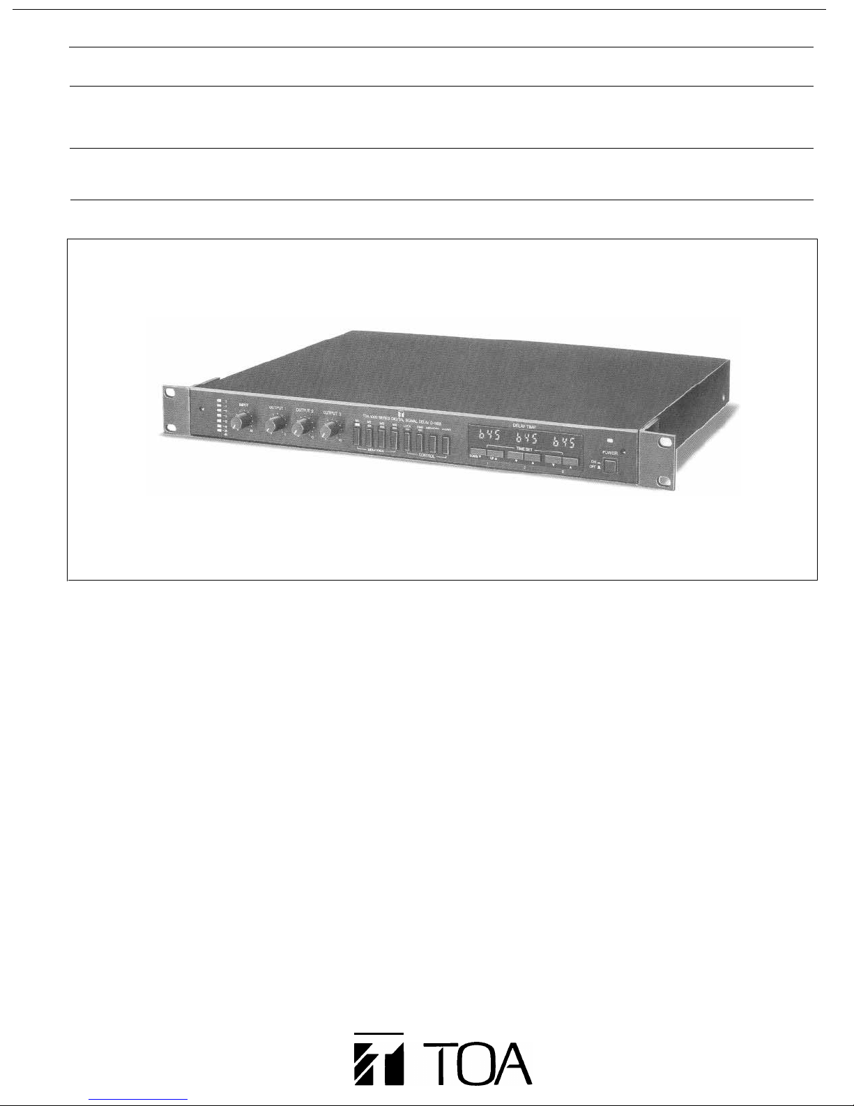
DIGITAL SOUND DELAY
D-1103
DESCRIPTION
The TOA D-1103 is a One-by-Three Digital Delay, designed
for a wide variety of applications such as theaters, concert
halls, houses of worship, auditoriums, large meeting rooms,
arenas and stadiums.
Delay times range from 10 microseconds (1/8 inch) to 655
milliseconds (approx. 750feet). Ten-microsecond increments are maintained throughout the entire delay range,
giving the D-1103 the ability to achieve the extended delay
required by remote speaker/cluster locations and simultaneously to perform the microsecond delay required for
component alignment.
The use of 16-bit, 100kHz analog-to-digital conversion
allows the D-1103 to achieve superb audio quality, with
dynamic range better than -90dB and THD below 0.03%.
Delay information may be stored in four non-volatile preset
memories, permitting instant set-ups. The preset memories
can be accessed with front panel switches or remotely via
contact closures. This permits simultaneous activation of
several interconnected units, either externally or by means
of a master D-1103 unit. A removable screw-terminal link
sets the status of the D-1103 as a master or slave unit.
A rear panel protect switch disables all front panel functions
except level controls, to prevent tampering. A smoked
plastic security cover is included to restrict access to all
front panel controls.
An automatic bypass function permits complete signal
bypass of the unit in the event of an AC power loss.
Terminal strip connections are used for electronically
balanced inputs and outputs. High quality, low distortion
input and output transformers with 30Hz20kHz response
are optional and installation requires no soldering.
A seven-segment multi-color LED level indicator assists in
proper gain staging. AC line noise suppression is built in to
ensure reliability, The D-1103 occupies one standard EIA
rackspace.
FEATURES
1. Three signal delay outputs.
2. Adjustable 0655 millisecond delay in summed
10-microsecond and 10-millisecond steps.
3. Four storage memories for delay settings.
4. Remote preset-selection terminal strip.
5. Automatic bypass circuitry in case of AC power loss.
6. AC noise suppressor protection.
7. Protect switch disables front-panel pushbuttons.
8. Security cover supplied.
9. Optional input/output isolation transformers.
Page 2
SPECIFICATIONS
PERFORMANCE:
Frequency Response
Total Harmonic Distortion
Hum and Noise
Delay
Time 0 to 655 msec
Steps
Propagation Delay
A/D Conversion
Memories
INPUT & OUTPUT:
Input
Type
Input Impedance
Rated Input Level
Maximum Input Level
Outputs (x3)
Type
Recommended Load
Rated Output
Maximum Output Level
CONTROLS & PANEL FUNCTIONS:
(Front Panel)
Input Level Control
Output Level Controls
Level Meter
Type
LED Points
Memory Selection
Fine
Lock
Memory
Clear
Setting
Display
Power
(Rear Panel)
Protect
Input
outputs
Ground
Remote Selection
Fuse
Power Socket
POWER:
Power Requirements
Power Consumption
PHYSICAL:
Dimensions (W x H x D)
Net Weight
OPTIONAL
ACCESSORIES:
Designed for UL Approval.
*0dB
IS
referenced to 0.775V RMS. unless otherwise stated.
20Hz to 20kHz, ± 1dB
Less than 0.03%
At least 90dB below maximum output
10 µ sec & 1 msec scales (summed)
µ
sec
100
16-bit at 100kHz Sampling Rate
Four-selectable via front panel buttons or
rear panel dry contact to screw terminals.
One master controls up to 15 slave units.
Electronically balanced (Transformer optional)
10k ohms
+ 4dB*
+ 18dB*
Electronically balanced (Transformer optional)
600 ohms or higher
+ 4dB* at 600 ohms
+ 18dB*
Attenuation type
x 3; Attenuation type
Headroom Indicator; 0 indicates 3dB
below maximum level
Seven segments (Red at 0 and -3dB;
Green at -6, -9, -12, -16, and -26dB.)
4 pushbuttons with LED status indicators
Fine/Coarse Display Pushbutton with
LED status indicator
Disables function pushbuttons except
memory selection and Fine
LED status indicator
Memory Store
Displayed Delay Time Clear
Up/Down Buttons (x 3)
3-digit numeric display (x 3)
On/off pushbutton with LED status indicator
On/off slide switch; Disables all front panel
pushbuttons
Screw terminals (H=Hot, C=Cold, E=Ground)
x 3; Screw terminals (H=Hot, C=Cold,
E=Ground)
Signal Ground to Chassis Ground
(removable link)
4-presets; Screw terminals; Selection via
dry contacts to E
Master designation by removal of D/E link
250V 0.3A Slow-blow Type (120V version)
250V 0.1A Slow-blow Type (220V/240V version)
EIA AC power cable socket
AC mains, 50/60KHz
15 watts
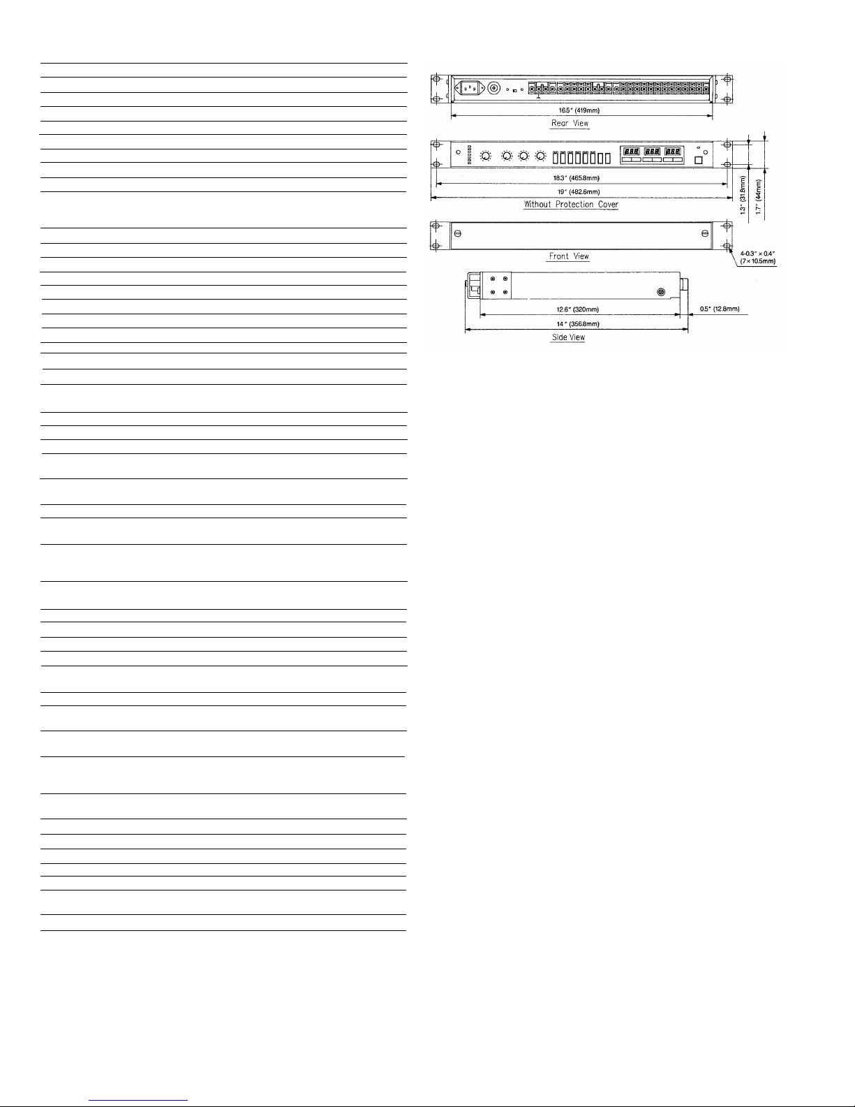
19.0 x 1.7 x 14.0 inches (483x 44 x 357mm)
EIA Rack Mount
9.7 Ibs. (4.4kg)
LT-101 Input Transformer
LT-102 Output Transformer (one per output)
APPEARANCE AND DIMENSIONAL DIAGRAM
ARCHITECTS AND ENGINEERS SPECIFICATIONS
The digital signal delay device shall be capable of delaying an audio input
signal to each of three independently adjustable outputs. The minimum
output time setting shall be 100 microseconds, including propagation
delay, and the time delay at each output shall be adjustable in 10-
microsecond steps up to maximum delay of 655 milliseconds. The unit
shall use 16-bit A-to-D conversion with a 100kHz sampling rate, and shall
have a maximum output-to-noise ratio floor of greater than 90dB. The input
circuitry shall be electronically balanced and shall accept either balanced
or unbalanced sources. The balanced input impedance shall be 10k
ohms. Each output circuit shall be electronically balanced and capable of
driving a load of 600 ohms or greater. The unit shall accept optional input
and output transformers which shall be internally installed via standoffs
and plug-in connectors. A7-segment LED input headroom display shall
indicate 3dB below maximum output for the combination of input and input
level control settings. Frequency response shall be flat (±1dB) from 20Hz
to 20kHz. The digital delay device shall include a digital display that can
be set to indicate the time delay of Outputs 1, 2 and 3. A front panel
Fine control shall allow the user to set the output delay for output 1, 2 or
3 in summed high resolution (1 O-microsecond step) or low resolution
(1 -millisecond step) modes. A Lock mode shall be provided which
disables all front panel pushbuttons except the memory selection and
Fine keys. A back panel Protect switch shall disable all front panel
pushbuttons, leaving only input and output level controls functional. A
security cover shall be provided to protect the front panel controls from
being tampered with. The delay unit shall provide four preset memories for
storage of delay-time settings. The preset memories shall be accessible
via front panel pushbuttons or remotely by means of contact closures
through a rear panel terminal strip. Up to 15 delay units shall be
configurable, with a single master unit to initiate preset selection for all
slave units. The unit shall contain a relay circuit which bypasses all internal
electronics in the event of power failure. lnput and output connections
shall be made via rear panel terminal strip connectors. The unit shall
measure 19.0" wide x 1.7" high x 14.0" deep (483 x 44 x 357mm) with rack
mount ears attached and shall occupy one standard EIA rack space. AC
noise suppression circuitry shall be built in to increase reliability. The unit
shall be a TOA Model D-1103 Digital Signal Delay.
Page 3

OPTIONAL MATCHING TRANSFORMERS APPEARANCE AND DIMENSIONAL DIAGRAM
LT-101
Input Transformer
LT-102
Output Transformer
LT-101/LT-102
SPECIFICATIONS
Model No.
Impedance 10k ohms: 10k ohms
Frequency Response
Distortion
Constant Loss
Weight
Accessories
*0dB=0.775Vrms
**Each transformer mounts at predrilled chassis hole locations. Transformer connections are
made via plug-in multi-pin connectors. No soldering is required.
LT-101
30Hz to 20kHz at ±0.15dB
Less than 0.2% (50Hz, 5dB*)
Within 15dB (at 1kHz, 1V)
0.1 Ibs. (44g)
Sleeve; 2, Screw; 4
LT-102
600 ohms: 600 ohms
BLOCK DIAGRAM
CHARACTERISTIC DIAGRAMS
*Group Delay-Frequency
Amplitude-Frequency *Distortion-Frequency
**Specifications are subject to change without notice.
Page 4

TOA Corporation
Printed in Japan 833-64-109-40
 Loading...