

Page 1
Operating Instructions
MIXING CONSOLE
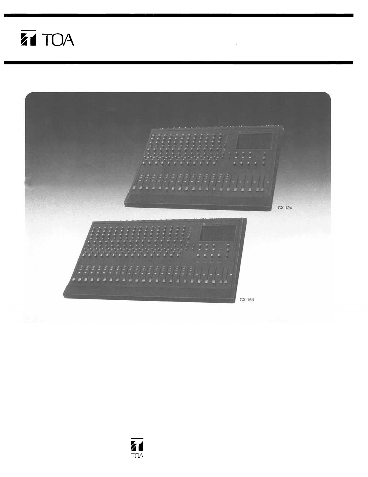
CX-124
CX-164
Please follow the instructions in this manual to obtain the optimum results from
these units. We also recommend you to keep this manual handy for future reference.
TOA Corporation
KOBE, JAPAN
Page 2
Contents
Precautions
General description
Features
Panel facilities
Front panel
[Channel input section]
[Aux Return input/Stereo IN input section]
[Output section]
Rear panel
Connection diagram for CX-124 and CX-164
Assembling input transformers
Specifications for input transformers
Input and output specifications
Characteristic diagrams
Block diagram
Level diagram
General specifications
Dimensional diagrams
Precautions
2
3
3
4
6
7
9
11
12
12
13
13
14
15
16
16
Power supply
Use within AC mains ± 10% (50Hz/60Hz)
Power switch
The power switch should be ON after all connections have been completed.
When the power switch is turned to ON/OFF, turn all of the output level controls to minimum position
to prevent damage to speakers, etc.
XLR type audio connectors are factory-wired as follows:
Pin 1 ground (shield), pin 2 cold (low, minus) and pin 3 hot (high, plus).
Where microphone cables connected to unit close to the cables of the lighting system, noise may
arise from it. Do not close each cable. In such the case, use the 4-quad shielded microphone
cables.
Do not spill a liquid like water nor place inflammables or metal like hairpins inside unit. Their entry will
result in an electric shock and equipment failure.
Avoiding to install unit at following places:
exposing to direct sunlight
with high ambient temperature or adjacent to heat-generating equipment
exposing to high humidity or dust levels
susceptible vibration
close to equipment arising hum or noise.
– 2 –
Page 3

General description
The TOA CX-124 is a mixing console with 12 input channels, 4 Group outputs, 1 Stereo output (L-R) and
1 Sum output, and the TOA CX-164 is a mixing console with 16 input channels, 4 Group outputs, 1
Stereo output ( L- R) and 1 Sum output. These mixing consoles are designed for use in professional
sound reinforcement systems such as various concerts, recordings in the studio, etc., and provide the
versatility necessary to meet a wide range of requirements. The high performance and modular construction assures reliability, easy maintenance, and service-ability.
Features
2-channel Stereo input is provided in addition to the channel input, and can be connected to a stereo
playback deck and other auxiliary equipment without reducing the channel inputs.
An input transformer can be assembled optionally.
Pan pot control on each input channel directly assigns the fader output signal of the channel to
Stereo L and R, which is used as either six Group out busses or four Group out busses + Stereo L
and R busses.
– 3 –
Page 4
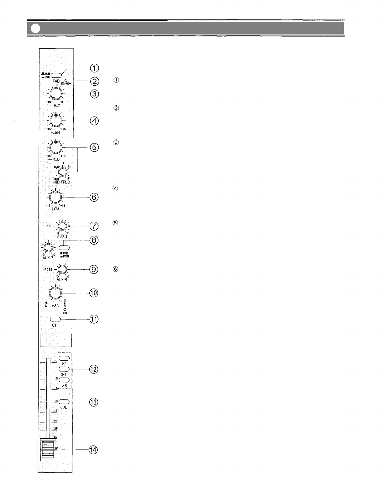
Panel facilities (Front panel)
[Channel input section]
Pad Switch [PAD]
Pad switch inserts a –20 dB pad ahead of the head amplifier. Adjust the PAD switch,
depending on the output level of microphones or associated equipment.
Signal/Peak LED Indicator [SIG/PEAK]
The dual color LED indicator lights green when the pre-EQ signal level reaches 20 dB
before from nominal level, and turns red when the signal level reaches 6 dB below clip-
ping, giving a visual reference for optimum setting of the trim control.
Input Trim Control [TRIM]
The Trim control adjusts the gain of the preamplifier stage of the associated channel,
providing 40 dB of gain control. The Trim control and Pad switch of each channel
should be properly adjusted so that the peak LED is just being to turn red from green
or only flash red occasionally. This will ensure lowest distortion level and optimum signal to noise ratio.
High Equalizer Control [HIGH]
The High EQ control alters the high frequency response of the input channel, providing
±15 dB at continuously variable active shelving equalization. The "0" detent position
provides flat audio response.
Mid Equalizer Control [MID]/Mid Equalizer Center Frequency Control [MID FREQ]
The Mid EQ frequency control alters the center frequency of the Mid EQ control in the
range from 300 Hz to 4 kHz.
The Mid EQ control alters the mid frequency response of the input channel, providing
±15 dB at the center frequency of peaking equalization. The "0" detent position pro-
vides flat audio response.
Low Equalizer Control [LOW]
The Low EQ control provides ±15 dB at continuously variable active shelving equaliza-
tion. The "0" detent position provides flat audio response.
– 4 –
Page 5

Aux 1 Control [AUX 1]
This control determines the level of the pre-EQ and pre-fader input signal to be fed to the Aux 1
buss. The position provides nominal level.
Aux 2 Control [AUX 2]/Pre-fader, Post-fader Select Switch
This control determines the level of the input signal to be fed to the Aux 2 buss. The Aux 2 control is
associated with the pre-post EQ and fader selector switch, which permits its assign to be either pre
or post EQ and fader.
The position provides nominal level.
Aux 3 Control [AUX 3]
This control determines the level of the post-fader input signal to be the Aux 3 buss. The position
provides nominal level.
Pan Pot
This control assigns the input signal of each input to the Group 1 and 2, or 3 and 4, or Stereo L and
[PAN]
R busses selected by assign switch for localization of sound image.
Channel Switch [CH]
This switch connects or disconnects the input signal to the mixing busses. The LED indicator lights
orange when the channel on/off switch is "on".
Assign Switch [1·2, 3·4, L·R]
This switch selects the buss the signal input to each channel is to be transmitted to. It is possible to
place busses assigned by the Pan pot control. Setting all of the Group to Stereo switches on the output section to OFF turns the Stereo L and R busses into Group busses, increasing the number of
Group busses to six.
Cue Switch [CUE]
The Cue switch is for monitoring the pre-fader signal in each input channel through Headphones and
Cue output. The switch is a "push-on push-off" type. When more than two switches are "on", the sig-
nals are combined.
Channel Fader
The fader provides continuously variable adjustment of the channel's output to the mixing busses.
The nominal level is at the "0" position, with the fader retaining a 6 dB margin.
– 5 –
Page 6

[Aux Return input/Stereo IN input section]
Power LED indicator [POWER]
The green LED indicator lights when the power switch is set to "on" position.
Aux Return Assign Switch [1·2, 3·4, L·R]
This switch selects the buss the signal input to Aux Return is to be transmitted to. The
signal can be transmitted to the Group 1 and 2, or 3 and 4, or Stereo L and R busses.
Aux Return Level Control [AUX RETURN]
This control determines the amount of aux signal returned the Group or Stereo busses
through the Aux return jack on the rear panel.
The position provides nominal level.
Cue Switch [CUE]
The Cue switch is for monitoring the pre-Aux return control signal through Headphones
and Cue output.
Stereo Input Aux 1 Control [AUX 1]
This control determines the level of the pre-fader stereo input signal to be fed to the
Aux 1 buss.
Stereo Input Aux 2 Control [AUX 2]
This control determines the level of the pre-fader stereo input signal to be fed to the
Aux 2 buss.
Stereo Input Assign Switch [1·2, 3 0·4, L·R]
This switch selects the buss the signal input to Stereo in 1 and 2 is to be transmitted
to. The signal can be transmitted to the Group 1 and 2, or 3 and 4, or Stereo L and R
busses.
Cue Switch [CUE]
The Cue switch is for monitoring the pre-Stereo input fader signal through Headphones
and Cue output.
Stereo Input Fader 1, 2
The fader provides continuously variable adjustment of the stereo channel's output to
the mixing busses. The nominal level is at the "0" position, with the fader retaining a 6
dB margin.
STEREO IN
– 6 –
Page 7

[Output section]
GROUP
STEREO
– 7 –
Page 8

Aux Send Control [AUX SEND 1, 2, 3]
This control is provided to adjust the overall signal level of the aux mix to the Aux Send outputs. The
position provides nominal level.
Cue Switch [CUE]
The Cue switch is for monitoring the pre-Aux send control signal through Headphones and Cue output.
Group Pan Pot [PAN]
This control assigns the Group fader output signal of the each Group to the Stereo L, R mixing busses when "GROUP TO STEREO" switch is "on".
Setting all of the Group to Stereo switches on the output section of OFF turns the Stereo L and R
busses into Group busses, increasing the number of Group busses to six.
Group to Stereo Switch [GROUP TO STEREO]
This switch connects or disconnects the group output signal to the stereo mixing busses. LED indica-
tor lights orange when the Group to Stereo switch is "on".
Cue Switch [CUE]
The Cue switch is for monitoring the pre-Group output fader signal through Headphones and Cue
output.
Group Output Fader
The Group output fader provides continuously variable adjustment of the group's output signal to the
Group output connector and Stereo L, R busses. The nominal level is at the "0" position, when the
fader retaining a 6 dB margin.
Output Meter
The LED bargraph meter indicates the Group output 1, 2, 3, 4, Aux Send 1, 2, 3, Sum output or
Stereo output L, R. The meter indicates 0 dB with +4 dB nominal output.
Meter Select Switch [METER]
The meter indicates the Group output 1, 2, 3, 4 when the meter select switch is set in the "release"
position, and indicates the Aux 1, 2, 3 and Sum output when the meter select switch is set in the
"push" position.
Headphone Jack
The Headphone jack will accept any stereo headphones with 8 ohms impedance or higher.
Headphone Level Control [PHONES]
The Headphone level control adjusts the corresponding cue signal fed to the Headphone output
when the Cue switch is on. When two or more of the Cue switches are on, the control adjusts the
corresponding combined cue signals.
Cue Output Control [CUE OUT]
The Cue output control adjusts the corresponding combined cue signal fed to the Cue output jacks.
Sum Output Control [SUM OUT]
The Sum output control adjusts the corresponding combined post-Stereo output fader signal to the
Sum output connector. The position provides nominal level.
Cue Switch [CUE]
The Cue switch is for monitoring the pre-Stereo output fader signal through Headphones and Cue
output in stereo signal.
Stereo Output Fader
Fader provides continuously variable adjustment of the Stereo L-R output to the Stereo output connector. The nominal level is at the "0" position, when the fader retaining a 6 dB margin.
– 8 –
Page 9

Panel facilities (Rear panel)
Channel Input Connector [LOW-Z]
The XLR-type input connectors are electronically balanced with a nominal level of –60 dB and an impedance of 600 ohms, and will accept signals from –60 dB to 0 dB. Phantom powering is provided
for use with condenser-type microphones (see PHANTOM), and once again the proper adjustment of
Pad and Trim control [PAD/TRIM] and input fader will insure optimum signal to noise ratio and minimum distortion.
LOW-Z input connector is automatically disconnected when the corresponding HIGH-Z input jack is
used.
Channel Input Jack [HIGH-Z]
This standard 1/4" phone jack is balanced, with a nominal level of –60 dB and an impedance of 10k
ohms, and will accept signal from –60 dB to 0 dB.
Accessory Input Jack [ACCESSORY IN]
This standard 1/4" phone jack is unbalanced, with a nominal level of –10 dB and an impedance of
10k ohms. The Accessory jacks allow signal processing and effect devices to be inserted into the
signal path. The regular signal path is interrupted when a plug is inserted into the Accessory in jack.
Accessory Output Jack [ACCESSORY OUT]
This standard 1/4" phone jack is unbalanced, with a nominal level of –10 dB and an impedance of
1k ohms.
Phantom Power Switch [PHANTOM]
The Phantom power switch on each 4 channels permits the user to supply 24 V DC through the XLRtype channel input connectors to condenser microphones. If phantom power is not required, the
switch must be in the "off" position.
Aux Return Input Jack [AUX RETURN]
These 1/4" phone jacks are unbalanced, and can be used in conjunction with the Aux send jack to
connect an outboard effect device (ie., Delay or Reverb) to this mixing console. The Aux return jack
should be connected to the output of the effect. Nominal input level is +4 dB with an impedance of
10k ohms.
Note: Connect to both "AUX RETURN L-R" when an outboard effect device has a Stereo output from
two unbalanced 1/4" phone plugs. The outboard effect device's stereo Left and Right chan-
nels are then assigned to the Group 1 and 2, or Group 3 and 4, or Stereo L and R busses,
respectively.
Connect to "AUX RETURN R/MONO" when the outboard effect device has a mono-output, the
mono signal will automatically be assigned to both Group 1 and 2, or Group 3 and 4, or
Stereo L and R busses.
– 9 –
Page 10

Stereo Input Jack [STEREO IN]
These RCA pin jacks are unbalanced, with a nominal of –10 dB and an impedance of 10k ohms.
The Stereo input jacks should be connected to an outboard stereo unit (ie., Tape deck, CD player).
Cue Output Jack [CUE OUT]
These 1/4" phone jacks are unbalanced, and provide the same signal as the Headphone output, and
are used for monitoring the signals of the Cue busses through monitor speakers. This jack has a
nominal output level of +4 dB and an impedance of 1k ohms.
Aux Send Jack [AUX SEND]
These 1/4" phone jacks can be used in conjunction with the Aux return jack to connect an outboard
effects device (ie., Delay or Reverb) to this mixing console. The Aux send jack should be connected
to the input of the effect. Nominal output level is +4 dB with an impedance of 1k ohms.
Recording Output Jack [REC OUT]
These RCA pin jacks are unbalanced, with a nominal output level of –10 dB and an impedance of 1k
ohms. These jacks provide pre-Stereo fader signals for connection to tape recorders.
Group Output Connector [GROUP OUT]
The electronically balanced XLR connectors have a nominal output level of +4 dB and an impedance
of 600 ohms.
Stereo Output Connector [STEREO OUT]
The electronically balanced XLR connectors have a nominal output level of +4 dB and an impedance
of 600 ohms.
Sum Output Connector [SUM OUT]
The electronically balanced XLR connector has a nominal output level of +4 dB and an impedance
of 600 ohms.
Power Switch [POWER]
This switch provides AC power to the mixer. Power should only be applied after all audio connections
have been completed. The power LED indicator lights when the switch is "on".
AC Power Cord
– 10 –
Page 11

Connection diagram for CX-124 and CX-164
Tapedeck for play back
Power amplifier
Effector etc.
Tapedeck for recording
Microphone
Power amplifier
Main speaker
Monitor speaker
– 11 –
Page 12

Assembling input transformers
The CX-124 and the CX-164 are designed with the electronically balanced inputs, however, optional input transformer IT-M4CX (for microphone input) or IT-L4CX (for microphone or line inputs) can be builtin the consoles, and their specifications are changed into the transformer input system. The input transformer is used only for four channels.
How to assemble the input transformer.
Turn the Power switch to OFF and ensure to unplug the AC power cord from the AC outlet.
Remove the eight fixing screws on the rear panel.
Lift the rear panel up to remove it, and for fix ing, insert groove of rear panel into both metals on
the left and right side panels.
Take out connector from part.
Fix the input transformer using the attached three screws as shown in the figure.
Insert connector into part.
Insert connector into part.
Assemble the rear panel in reverse manner of removing it
Note: Do not touch other parts inside
unit than instructed in this assembling manual.
This will lead to failures of the mixing console.
Specifications for input transformers
Models
Frequency Response
Distortion
Maximum Input Level
Constant Loss
Impedance
IT-M4CX
50 Hz~15 kHz within ±1.0 dB
Less than 0.4% (50 Hz, –20 dB)
–2 dB 50 Hz 1%
Within 1.5 dB at 1 kHz
600
/600
– 12 –
IT-L4CX
30 Hz~20 kHz within ±0.15 dB
Less than 0.2% (50 Hz, +5 dB)
+ 11 dB 50 Hz 1%
Within 1.5 dB at 1 kHz
600
/600
Page 13

Input and output specifications
INPUT SPECIFICATIONS
Input
CH INPUT
1~12
(16)
ACCESSORY IN 1~12(16)
STEREO IN L, R 1, 2
AUX RETURN L, R/MONO
PAD
ON[20dB]
OFF
[0dB]
OUTPUT SPECIFICATIONS
Output
GROUP OUT 1~ 4
STEREO OUT L, R
SUM OUT
AUX SEND 1, 2, 3
ACCESSORY OUT 1~12(16)
CUE OUT L, R
REC OUT L, R
PHONES
Contents in ( ) stand for CX-164 data.
For Use with
TRIM
–40
0
Norminal
LOW-Z
Mics or Lines
HIGH-Z
Lines
Lines
Lines
Lines
For Use with
Norminal
Lines
Lines
Lines
Lines
Lines
Nominal
0dB
–20dB
–60dB
–10dB
–10dB
+4dB
Output Level
Nominal
+4dB
+4dB
–10dB
+4dB
–10dB
1.5mW
Input Level
MAX. Before Clip
MAX. Before Clip
0dB is referenced to 0.775V rms.
Connector
+ 20dB
+
10dB
–30dB
+
10dB
+
14dB
+20dB
+ 26dB
+20dB
+ 20dB
+ 20dB
+
20mW
8dB
XLR-3-31 or equivalent
[Balanced]
Phone Jack [Balanced]
Phone Jack [Unbalanced]
Pin Jack
Phone Jack [Unbalanced]
Connector
XLR-3-32 or equivalent
[Balanced]
Phone Jack [Unbalanced]
Phone Jack [Unbalanced]
Phone Jack [Unbalanced]
Pin Jack
Phone Jack [TRS]
Characteristic diagrams (Input EQ Characteristics)
– 13 –
Page 14

Block diagram
– 14 –
Page 15

Level diagram
– 15 –
Page 16

General specifications
Frequency Response
+0.5, –1.0 dB 50 Hz~15 kHz
+0.5, –3.0 dB 20 Hz~20 kHz
Total Harmonic Distortion
0.1%
at +4 dB 1 kHz
Equivalent Input Noise (Rs=150 )
-130 dB (IHF-A)
S/N (Rs-150 )
69 dB (20 Hz~20 kHz) GROUP OUT or
70 dB (IHF-A) STEREO OUT
Crosstalk
–60 dB at 1 kHz
Maximum Voltage Gain
76 dB INPUT GROUP OUT
82 dB INPUT GROUP OUT STEREO OUT
26 dB STEREO IN AUX SEND
Channel Equalizer
LOW 20 Hz ± 15 dB Shelving
MID 300 Hz~4 kHz variable ±15 dB Peaking
HIGH 20 kHz ±15 dB Shelving
Peak Indicator
LED turns on when the pre-fader and post EQ signal
reaches 6dB before clip.
Phantom Power
+24V DC
AC Line Voltage
AC Mains, 50/60 Hz
Power Consumption
CX-124 48 W
CX-164 52 W
Weight
CX-124 23 kg (50.7 Ib.)
CX-164 27 kg (59.5 Ib.)
Specifications are subject to change without notice.
0dB is referenced to 0.775V rms.
Accessories
Operating instructions
Warranty card (for USA and Canada only)
1
1
Dimensional diagrams
CX-124
CX-164
mm
(in.)
TOA Corporation
KOBE, JAPAN
 Loading...